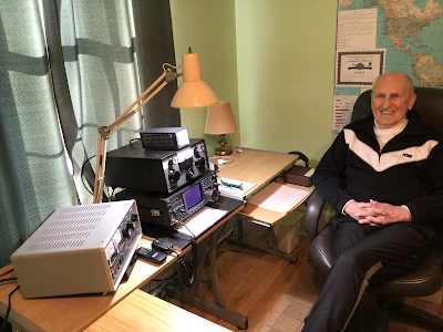
Podcasting since 2005! Listen to Latest SolderSmoke

Showing posts sorted by date for query ET-1. Sort by relevance Show all posts

Thursday, April 9, 2020

WB9IWT's Quarantine Mighty Mite and N3FJZ's "Hiram Percy Maxim Recognition Factor"


Leif WB9IWT has, during the emergency, been working on a Michigan Mighty Mite (See pictures above and below).  FB Leif.  

But also check out the very astute comment from Rick N3FJZ (below) .  I am, of course, all in favor of the HPMR Factor.  Almost all of my rigs would score quite high.    Others, I know, would seek a low score.  To each his own.  This is all for fun.  

Leif,

Great work.  If a ham from the 1920's were to see this rig, they
probably wouldn't recognize the actual components right away (but
knowing hams, they would no doubt figure it out), but the breadboard
layout circuit flow would be immediately recognizable; e.g. the plug-in
crystal, the coil, binding post.  The transistor and variable capacitor
may baffle them at first, but seeing there are three leads on the
transistor would start to give them clues.

That's the cool part about analog discrete component radio, no matter
how many years go by, and the appearance and size of the actual
components change, the physics of what's going on at the electron level
stays the same (SDR not withstanding).

I guess this could be a litmus test for us analog radio builders.  It
could be called the "Hiram Percy Maxim Recognition Factor" or "HPMR
Factor" with a range of 0 to 1.  After you  build your rig, take a look
at it and pretend that you could present it to Mr. Maxim and the more he
could understand the circuits, components and circuit flow on his own,
the closer to a factor of 1 your radio would achieve.  For example, an
SDR might only achieve a factor of .1 or even maybe 0, where as your rig
may achieve a factor of .8, and one of your crystal receivers would
definitely get a 1.

Someone could even workout a check list or formula where you would add
or subtract some fractional numeric values for each component you used;
e.g. you would subtract some value for every IC chip, microprocessor or
LCD display you use, and add some fractional value for each hand wound
coil, vacuum tube/valve or open air variable capacitor, et cetera.

Fun to think about.

Keep building.

Rick - N3FJZ


Sunday, December 15, 2019

Hangin' it up (the ET-2)


My ET-2 minimalist QRP CW adventure is (for now) officially over.   I have taken the rig - festooned with the callsigns of all the stations I contacted -- and have put it up on the wall.  This may be a new form of art.  I think I am the first radio amateur to do this.  I think it is pretty cool. 

Here are the stats:   I made 20 contacts with the rig. I had it on the air from 12 October 2019 to 7 December 2019.    Seventeen of the contacts were the result of my posting pleas for help on the SKCC Sked page and/or the Summit DX page.  Three of the contacts were completely random. One station -- W1PID -- provided four of the contacts.  Thanks Jim. 

My power out was usually around 100 milliwatts.  I used either a 40 meter coax fed dipole or a 135 foot doublet fed with window line. 

My best distances were Wisconsin and Georgia. 

Crystal control was the real limiting factor.  100 milliwatts didn't seem to be much of an impediment. The most amazing thing about this rig is the N0WVA regen receiver.  It took a lot of peaking and tweaking, and it took some skill to operate. but once I got it going it was an amazingly good receiver.  Really Amazing for just ONE J-310 FET. 

The last contact was really nice.  I was calling CQ and AA8OZ came back.  He was in a cabin on a trip with some scouts.  He too was on a wire antenna.  He was one of those guys who said WOW! when I told him about the rig.  We had a nice long conversation on 40.  It was a great way to wrap up the ET-2 adventure. 

Thanks to all who helped me make contacts and for all those who tried to work me. Thanks to N0WVA for the regen inspiration. And thanks to Glen Yingling W2UW (SK) for the ET-1 idea. 

The rig is standing by.  On the wall.  Perhaps it will return to service, maybe during solar max. 


Tuesday, December 3, 2019

ET-2 Contact #18 W4FOA -- RANDOM, UNSCHEDULED, AND NOT SPOTTED (Video)


On December 1, 2019,  my 100 milliwatt signal flew more than 500 miles to reach Tony W4FOA in Chickamauga, Georgia. And -- icing on the cake -- this was a random contact.   Tony just heard my CQ on 7038 kHz -- he had not been alerted to my CQ by any spotting site or by the SKCC Sked page.  I made a quick video of my side of the contact (above). 

In a follow-up e-mail Tony explained how my CQ sounded to him: 


"I was just listening on the 40 meter band and having been a QRP'er for 50+ years, I tend to notice the weaker stations, thus explains my calling you.  Also, your signal had that little "sound" of "yesteryear" when signals were not all pure, hi.  Had it not been for the QSB and QRN we could have had a long chat despite the weak signal from your QRPp.  Over the years I have QRP DXCC, 2 way QRPARCI WAS, and my best DX was two QSO's with 2 different VK7 stations on 40 when I was running 1 watt.  I've had a lot of different QRP rigs and still have some home brew stuff plus a couple of HW8s, HW9, Elecraft K2, etc..."  

From Tony's QRZ.com page, we learn more about his ham radio activities (note his homebrew rigs and his obvious affection for the Drake 2B and 2BQ) 

First licensed as WN4FOA in April 1954. Other calls held include EL2AD, 7Q7AA, PY1ZBA. Prefer to work CW but I do work some SSB, primarily DX-related. Enjoy chasing DX on all HF bands. Have 9BDXCC and I now have worked and confirmed all of the current DXCC countries . I enjoy QRP operation and currently use an Elecraft K2 (#2213),Ameco AC-1, Kenwood TS-130V SW-40, DC-40, HW-8 (2), Heathkit HW-9 Deluxe (WARC) PSA-9 HFT-9B SP-99 HM-9 HD-420 VLF, MFJ 40T and MFJ 40V VFO,  and a homebrew 6AG7/6L6 or a 6C4/5763  etc. I also enjoy operating boatanchor gear which includes a Johnson Viking Adventurer, Viking Challenger,  an Eico 720 and an Eico 723 with a HG-10B VFO and a Heath AT-1 and a Drake 2NT. Recently added a neat Lysco 600 transmitter and a Knight Kit T-60, Johnson Viking II, and a Ten Tec 544.  Boatanchor receivers include a Hallicrafters SX-100, SX-110, SX-71, Drake R4C and the incredible Drake 2B/2BQ combo. Recently added a Kenwood TS-830S, VFO-240, AT-230 and SP-230.


Tony W4FOA
Thanks a lot Tony.  73

Thursday, November 21, 2019

Notes and Video on Doug N0WVA's Amazing Single Transistor Regenerative Receiver


When I had trouble getting the regen receiver in W2UW's ET-1 circuit to work, I turned to the internet and -- through AA7EE's site -- found the circuit of Doug N0WVA.   This circuit has completely changed my attitude toward regen receivers.   I have been exchanging e-mails with Doug -- below is a compilation of the info and regen-wisdom that he has shared.  More to follow... Thanks Doug. 
From Doug N0WVA: 

I came up with the diode after exploring ways to ditch the source r/c combo. The thinking was the closer I could get the source to ground the less voltage/capacitance fluctuations the gate would see.  Also I hated seeing everyone using .01 bypass to avoid audio oscillations and also losing audio gain. 

 The green LED works good but even better is directly grounding the source. Then feed a small negative bias through the gate leak resistor , adjustable via a potentiometer.  

On video, the audio is taken straight from the radio shack headphones that are connected to the audio transformer. The headphones are held directly to the phones case ( no hole for the microphone seen on the phone)  

The variometer is  made with I think a 1.25 inch pill bottle and the tickler inside is around an inch in diameter pill bottle. I used a pharmaceutical syringe's outside tube for a shaft. The tickler form has a couple holes cut for the shaft to pass through, it is a friction fit, more like slits cut and the rod pushed through. I used the soldering iron to melt round holes on the actual outside coil form for the shaft to turn on. On the back of the shaft is a small screw that goes through the outside coil form and screws into the syringe center hole that holds it in place. The tickler is one turn, I think, and routed through the inside of the shaft via small holes melted with the soldering iron.

A couple tweeks to mention is instead of a resistor in the gate, use a choke for less noise, makes a big difference, especially if you listen to AM.  Also I have been using a gimmick for the gate cap.  Just maybe a #36 enamel wire wrapped around  the hot tank lead 5 or 6 times and then I remove turns till the thing stops oscillating, then add a turn. This helps cut down even more on strong signal pulling. 

I have always been on a quest for more performance out of the least parts. This design was about as far as it could go, I think....

I have never done any real sensitivity tests on the regen, so you have gone farther than me already. One thing was noticed though is the gate resistor does add a lot of noise, especially noticeable just under oscillation in AM detection mode.  So I took a one meg 1/4 watt resistor and wound as many turns of #38 wire on as I could, probably around 80 turns, then subbed it out for the gate leak.  This dramatically improved the noise level just under oscillation. This was with a simple antenna band noise test. I think it also improved the noise under oscillating conditions. 

Adding extra antenna coupling will probably help a lot, but, there is a point where we start getting too much strong signal pulling.  The strong external bias battery trick will also improve this, although at the cost of extra parts.

Saturday, November 9, 2019

SPRAT, the FETer, DLR headphones, and recent QSOs on the ET-2


Yesterday we had QSO #13 on the ET-2.  This was with Jim W1PID.  In an earlier contact Jim told me I had some chirp.  I fiddled with the coupling cap and the bias pot and am now T9!  These days, chirp is an endearing, nostalgic problem to have.  Thanks for the report and QSOs Jim! 

Contact #9 was with Fred K9SO.  He is in Wisconsin and QRZ.com put our distance at 633 miles.  That is our DX record so far.  Not bad for 92 milliwatts to a dipole on 40 meters. 

Most of my contacts come as a result of pleas for assistance on DX Summit or the SKCC Sked page.   But I did make one "random" contact: Contact #6 with N2VGA.  He just heard my CQ and gave me a call.  FB. 

I checked to see if OM Glen Yingling W2UW -- the guy who started all this with his ET-1 -- is still around.  He became a silent key in 2012.  But his ideas live on... 

SPRAT 137 (Winter 2008/09) has a great article by QRP hero G3XBM.  Roger built a version of the ET-1.  His was for 80 meters and he called it the FETer.   FB.   I was struck by his estimate of the sensitivity of the ET-1 receiver: -100 dbm.   I measured the N0WVA receiver (the one that I am using) has having a minimum discernible signal of -93 dbm.  Pretty close.  We may be at the limit of what you can expect from a single transistor receiver. 

SPRAT 137 had something else that really resonated with me.  G3YVF had an article on a minimalist rig using only one 6V6 tube.  Geoff opened the article with this warning "Don't try this unless you have a set of balanced armature type DLR 'phones as they are really sensitive."  I have a collection of old headphones that I picked up at hamfests in London years ago.  When building the ET-2, I checked all the old phones for sensitivity.  A set marked DLR was the most sensitive.  So Geoff's observation had been independently confirmed.   QRP Quarterly had an article comparing the sensitivities of old headphones -- we should dig that article up.   

SPRAT #137 is a reminder of what a great resource SPRAT -- The Journal of the GQRP Club -- really is.  As we say on SolderSmoke, if you are not a SPRAT subscriber you are just wrong!  Here is how to join GQRP and subscribe to SPRAT: http://www.gqrp.com/join.htm

Saturday, November 2, 2019

SolderSmoke Podcast #214 is FINALLY out!


WE ARE WORKING TO IMPROVE THE AUDIO QUALITY.  IN THE FIRST RELEASE OF THIS PODCAST SOME OF THE AUDIO WAS KIND OF MUFFLED.  I TRIED TO FIX IT THIS MORNING AND I THINK I MADE SOME IMPROVEMENTS.  THE IMPROVED AUDIO IS NOW AT THE LINK BELOW.  


4 November 2019 (shockingly late!)

http://soldersmoke.com/soldersmoke214.mp3

The visit of Farhan to Northern Virginia
"I heard this guy from Southern California on 20..."
Fire Report from Pete

Pete's Bench Report
"When you know stuff, you can do stuff!" 
The CRAP rigs 
Old Boatanchors -- the Swan 120  with SUPER STABLE ANALOG VFO! 
Ten Tec rigs dial cord replaced with Chinese digi sig counter 
Pete's 500 mW encounter with a QRO curmudgeon
The ZL2BMI Challenge has Pete building crystal filters
The Left Coast Loafer CW rig 

Bill's Bench Report

ET-2 Refinements
N0WVA's Regen Receiver 
Going from ET-1 to ET-2
J-310s vice MPF-102
100 mW from a single J-310
Receiver kind of deaf -103 dbm MDS
10 contacts so far in 9 states 
THREE contacts yesterday.
Worked Wisconsin - 633 miles on 92 mW 
We are at sunspot minimum. 
"Rage, rage against the dying of the light." 
Simplicity is the real reason for CW 

IDEA:  Get those Michigan Might Mites on the air! 
Use Reverse Beacon Network to see if you are getting out 
Use SDR receivers to make contacts

MAILBAG
DL1AJG
KC6SAX
W9VNE
KA4KXX
N0WVA
Zl2BMI
AJ6BD  


Sunday, October 13, 2019

More on the ET-2 : Better Pictures and More Circuit Description. Some Thoughts on Simplicity


So yesterday I made my first contact using my ET-2 rig.   Last night I got an e-mail from Gary, the fellow at the other end of that contact: 


Evening Bill, N2CQR….Yes I did learn about you from the spot on the DX Summit cluster. I tuned to the freq to see if I could even hear your 80 mW and you were a good real 569 when calling CQ.  You built up to a real 589 on the later transmissions. I did not have either of the two pre-amp positions on in the ICOM 756 Pro II. There was not any QRM on the freq either. Your spot indicating the 80 mW is what really got my attention.

My antenna is a 2 element yagi at about 115 ft and it really works great for me.

Thanks for the picture of the great little transmitter. Glad to be your first DX QSO with it. Hi Hi  Maybe again soon.  My pleasure to work you.
73, Gary, K4MQG
Fort Mill, SC

Farhan commented on yesterday's post, saying that it was hard to tell (from my pictures) where he rig started and ended.  He was right.  So this morning I have tried to clean up my bench a bit -- I hope these pictures are better.  

Above you see the whole rig.  The transmitter board is right next to the key that Farhan gave me.  You can see the 7040 crystal.  A C-Clamp holds to the bench the piece of scrap plywood that serves as the base for this rig.  Next to the C-Clamp you see the TR switch -- the just switches the antenna -- both transmitter and receiver are powered at all times.  I can hear the transmit signal in the headphones and this serves as my sidetone. 

Here is a close-up of the transmitter with the schematic below: 


The transmitter is VERY simple.  Nine parts, including the low-pass filter.  You can barely see the J310 FET to the right of the crystal. 

Here is the receiver:


I really like N0WVA's regen.  The green diode in the source circuit is the key.  This one does not squeal when you go into excessive regeneration (when you think about it, regens should NOT squeal at audio frequencies -- but most do).  Also, the green diode dims a bit when you are at the right amount of regeneration.  In the picture you can look down the tube of the variometer that Pericles HI8P gave me many years ago.  The big variable cap is from the junk box -- I think it may be from a Johnson Viking transmitter.  Note the long shaft with the insulating connector -- this is to reduce the hand capacity effect.  On the right you see a smaller cap with just one vane -- this is my fine tuning control --- with the smaller cap at mid range, I would just set the big capacitor to put the receiver at 7040 -- with the smaller cap I could tune +/- 12 kc.  I also used an insulating shaft on the smaller cap -- the connector for this one is from an old 1930s era regen that I picked up at the Kempton Part rally in London.

Instead of the audio transformer and Radio Shack headphones, I just used some old DLR-1 WWII Headphones.   They are very sensitive and work well. 

Lots of soul in this new machine:  The variometer from Pericles.   The WWII headphones.  The 1930s era shaft connector.  The circuit idea from the Autumn 2001 SPRAT.  Farhan's key. 

I recently read on Hack-a-Day of a new FPGA chip that has on it 35 BILLION transistors. I'm sure that thing can produce some fascinating results, but can anyone really understand it, or feel that they really BUILT something that has that kind of chip at its center?   On the other hand, I did rely on a lot of modern digi technology in this project:  The Reverse Beacon Network reported back that my unanswered CQs were in fact getting out (one as far as Kansas to K9PA).  And in the end I had to ask -- via the DX Summit Spotting cluster -- for someone to listen for me.   So I can't go full Luddite here.  And I wouldn't want to have to use a rig this simple every day.  No way.  It is just too hard to use. But there is a beauty and a challenge in simplicity.  There is some virtue in using just two transistors instead of 35 billion. 

Thanks to N0WVA, W2UW,  VU2ESE, HI8P, K4MQG, The G-QRP club and their inspirational journal SPRAT, the RBN and the DX Summit. 

Saturday, October 12, 2019

Success with my ET-2 --TWO TRANSISTOR RIG


In my effort to replicate the ET-1 rig of Glen Yingling W2UW, I had a hard time getting the receiver to work well with the single FET being switched between receiver and transmitter, so I retreated a bit and went with individual FETs for the TX and the RX.  This doubled the transistor count -- to TWO.  So it is an ET-2.

I also boosted the power to 80 milliwatts by putting 12 V on the transmitter.  The receiver was running off the 9V battery you can see in the left in the picture. 

Here is the story of the contact: 


To K4MQG from N2CQR:
Gary: Wow thanks for the QSO today.  I was using 80 mW transmitter that consists of just 8 parts!  The receiver was a regen using one single transistor.  So one transistor on transmit and one transistor on receive.  And it reached South Carolina.

I was about to give up hope.  I had been calling CQ for days.  Then I was talking to Rob VE4GV on 20SSB.  Rob suggested that I "spot myself" on one of the DX clusters.  So I did (see below).  Obviously you saw my spot and a minute or so later, SUCCESS!   I'm really pleased.

Attached is a picture of the rig.  The transmitter is around the crystal and the blue pot on the right.  The headphones are from WWII.  The receiver was powered by the 9V battery.  The regen uses a variometer given to me by a friend in the Dominican Republic in 1992.  The main tuning dial is connected to the cap by an adapter from a 1930s-era regen.  Antenna was a 40 meter dipole at about 25 feet.  Obviously your 3 elements a 115 feet were doing the heavy lifting.

Thanks again Gary!

And thanks to Rob for the suggestion on the spotting.

73  Bill N2CQR


Friday, October 4, 2019

Single Transistor Transceiver On the Air

I got my version of the ET-1 transceiver working.  As I described in previous posts, I first got the transmitter and the receiver working separately, each with their own J310 FET (oh the extravagence!) Then I built a switching arrangement that allowed for just one shared FET and very short leads.   I used a 4PDT "push button" switch from an old Ramsey Electronic LC meter. See the last picture for details. I use the tube from a pen to operate the switch (that's the green thing in the picture). 

It is inhaling and exhaling.  My 20 mW signal is being picked up on the Reverse Beacon Network, mostly in New England, but today in North Carolina.  

No contacts yet.  I may have to resort to scheduled contacts.  OM Yingling W2UW was operating during much better propagation conditions (2001), so I don't think I will ever get close to his impressive (23 states!) operating record.  

But it has been fun getting this thing going.  The N0WVA regen design is one of the best and simplest regens I've ever built.  It is really nice --hardly demonic at all.  

I can run the whole thing off one 9V battery. I think it is a cool looking machine. 


Sunday, September 15, 2019

Virginia to New Hampshire (one way) on 8 Parts and 20 mW


Having gotten the regen receiver portion of the ET-1 transceiver working nicely, I'm now working on the transmitter.  This is a much easier circuit to get going. (Check out the right hand side of the schematic below --- that is the transmitter.)  I have not made any contacts yet, but yesterday I called CQ on 7050 kHz and watched the Reverse Beacon Network to see if any of the skimmer stations picked me up.  Success!   W3UA up in New Hampshire received my signals. 

I was running about 30 milliwatts to my doublet antenna. The transmitter consists of EIGHT parts.  And three of them are the low pass filter. 

Next step:   Bring the transmitter and receiver together by using the switching scheme that OM Yingling used.  The RX and TX will share the same single FET (MPF-102 or J-310) with all three leads from the FET switched from TX to RX.   Then I will try for the elusive QSO with a single FET. 

More ET-1 related posts here: https://soldersmoke.blogspot.com/search?q=ET-1


Saturday, September 7, 2019

SolderSmoke Podcast 213 WE'RE BACK!

N6QW's Analog CW QRP Transceiver
SolderSmoke Podcast #213 is available. 

http://soldersmoke.com/soldersmoke213.mp3

7 September 2019

The dire consequences of our summer absence. 

50th PODCAST WITH OUR FRIEND PETE! 
THREE CHEERS FOR PETE! 

Pete's Bench Report

-- Transceiver Count:  FORTY!  
-- SDR RADIGS 
-- Colorful OLED screens
-- Pilgrims and Paisanos -- "Left Coast Homebrew SSB"
-- Pete builds a CW transceiver (see picture above)


Bill's Bench Report: 

-- Going minimalist
-- Tuna Tin 2 + Herring Aid 5 = Fish Soup 7 (and later 10)
-- My QRPp QSO with K1PUB overheard in Canada
-- Glen Yingling's ET-1 
-- Bill attempting a single transistor transceiver

SPACE NEWS

-- Antuino's Cubesat Origins. Farhan's Antuino Mods
-- Apollo 11 Anniversary
-- Possibly the best space book ever:  "Carrying the Fire" by Michael Collins
-- Chinese microsat sending eclipse pictures from the moon
-- LightSail 2 success
-- India has spacecraft in lunar orbit. 

Eric Sears ZL2BMI and Dino Papas KL0S on "QSO Today" Podcast

MAILBAG: 

ZL2PD's Sugar Cube VFO
N8WQ gets free samples
N5RWF Getting started, wisely wearing beret
VK2EMU Australian Ad for Collins Filters
W1PJE on new LDMOS PA transistors
KA4KXX Al Fresco 75 meter SSB rig with model plane engine mufflers!  

Forgot to mention:  W9TH still has manuals for whover owns Drake 2-B #4215.  Check your serial number! 

Monday, August 26, 2019

Single Transistor Regen Has QSO Potential (Video)


In my previous blog post I'd expressed skepticism about using a single transistor regen on the air.  But over the years I've learned to give new receivers a chance.  They usually don't work perfectly on the first try.  You have to work with them.  It is almost as if you have to peak and tweak a lot in order to get them to properly inhale signals from the ether.  

That has been the case with this little receiver.  I found some silly mistakes in my construction.  And I decided to try some more sensitive headphones.  I ditched the 1000 to 8 ohm AF transformer.  And I added a very small variable cap for fine tuning.  

The results are amazing. See video above. It performs as well as most of the direct conversion receivers I've built. It is remarkably stable.  

I do think I could make contacts with this receiver.   I might eventually go the full ET-1 route and try to do it with a single switched FET, but I think my next step will be to built a single transistor crystal controlled transmitter on the same piece of wood, and try to make some contacts with a two-transistor rig. 

Wednesday, August 21, 2019

Another Bout of Minimalist Regen Madness

My success with the Fish Soup 10 QRPp transceiver got me interested in further minimalization.  About ten years ago I built a rig presented in SPRAT 108 as the ET-1 by Glen Yingling W2UW.   It re-appeared in modified form as the FETer by G3XBM in SPRAT 137.  

This rig uses just ONE active device, an MPF-102 FET that is switched via a 3 pole double throw switch from transmit to receive.  The transistor is switched.  The receiver is a regen and the transmitter is a very simple crystal controlled one stage oscillator. See: 
https://soldersmoke.blogspot.com/search?q=ET-1  for info on my ET-1 effort. 
The transmitter was the easy part.  I don't think I made any contacts with this thing.  That has been kind of bugging me.  

So I tried it again.  Again, I had trouble with the receiver.  So I looked around for another single FET regen receiver design.   I found one on AA7EE's page.  It was designed by N0WVA:  
https://aa7ee.wordpress.com/2015/02/07/n0wvas-one-fet-regen-optimized-for-ssbcw-sounds-great/


I've had a variometer in my junk box since about 1994. (Given to me by Pericles HI8P. QEPD.) It was time to use it as the coil and ticker for this rig.   I liked the green LED in the source, and the promise that this thing would not oscillate at audio frequencies.  

I built in on one morning.  See pictures. It works.  I can hear CW stations.  But I think I would have a tough time making contacts with this thing.   OM Yingling worked 24 states with his ET-1.  Respect.  


Saturday, March 12, 2016

EMRFD Joy of Oscillation (Part 1)


Guys:

I have been catching up on the last few SolderSmoke podcasts after
that little QSO Today diversion.  I wonder how many others did the
same thing?  I have really enjoyed these recent 'casts.  Lots of
fantastic HB content.  Funniest moment was when Bill described his
post-project workshop as looking like the aftermath from an electronic
barfight.

I took a new ham up on a SOTA activation last year.  Then about a
month ago, he said that he wanted to do HF HB.  He said he had been
googling and found so much that he didn't know where to start.  I told
him that I'd be interesting in doing a beginner HF HB project with
him.

I could have pointed him to LBS, et al.  I could have pointed him to
the Michigan Mighty Mite.  I did neither.  I pointed him to:
http://web.cecs.pdx.edu/~campbell/EMRFD1dot34.pdf  Note the name of
the document.  I pointed him also to:
http://www.arrl.org/files/file/Product%20Notes/chapter_1.pdf 
(Did you guys know that chapter was online and free?)  We scaled to 20m and
kitted parts for this.  And parts for a 4th transistor PA for serious
QRO.  :-)

Two others joined us building for 40m.  Check out the attached photos
of the first 3.  The joy of oscillation was experienced by all.

After testing each oscillator, and borrowing from an article KK7B ran
in CQ VHF, I told each that he had to ID every 10 minutes.  Even
though nobody was going to hear these signals a few hundred yards
away.  (But it sounds loud on a shortwave portable a few inches away!)
 I even wrote out the dots and dashes for a couple of them.

Next stop:  to have everyone find a curbside TV discard, rip out some
parts, and get on 5 meters!  Haven't we gotten it back now, after the
transition to digital TV?   :-)

OK, maybe the next stop is to add some gain stages and experience the
joy of communication.  The joy of QSO-ification?  The joy of
EM-radiation?  :-)

Best regards,

Drew
kb9fko


2 Attachments

Monday, December 5, 2011

Messaging ET (METI), and Silicon-based Life Forms

My fellow beacon fans will like this one. The ultimate (REALLY ultimate) beacon! http://www.newscientist.com/article/dn21236-lets-build-a-beacon-to-tell-aliens-who-we-were.html?page=1

And then there is this article about silicon-based life forms. (At first I thought they were talking about us!) http://www.universetoday.com/91449/why-silicon-based-aliens-would-rather-eat-our-cities-than-us-thoughts-on-non-carbon-astrobiology/

Our book: "SolderSmoke -- Global Adventures in Wireless Electronics"http://soldersmoke.com/book.htmOur coffee mugs, T-Shirts, bumper stickers: http://www.cafepress.com/SolderSmokeOur Book Store: http://astore.amazon.com/contracross-20

Wednesday, June 17, 2009

Crystal Radios from Heaven, Regens from ?

Yesterday I was describing the heavenly sounds coming from my crystal radio. In a minimalist mood, this morning I fired up (an appropriate term!) my ET-1 regen rig. This is the single FET transceiver described in earlier blog articles. The contrast with yesterday's experience couldn't be starker. Instead of Gregorian chants, I was greeted by the screeches of excessive regeneration. The crystal receiver seemed to WANT to demodulate signals, the regen required all kinds of adjustment and coaching and, it seemed, black magic. All this made me think that while the crystal sets are heavenly, the regens seem like they are from the other place.
There is a Roman ham who has said he will try to have a contact with me using this ET-1 rig. One will be enough, then it will be back to direct conversion and superhets for me.

Sunday, March 29, 2009

SolderSmoke Podcast #104

http://www.soldersmoke.com

1 April 2009
Rome Marathon
Billy climbs Vesuvius!
Fixin' up old Toshiba laptop
Solar Power from Donuts and Tea!
Eldon's MEPT ET Phone home machine
More Catalan minimalism: The MOSquito
Book: Thunderstruck! Marconi history
SPECIAL ECHOLINK QSO WITH NIGEL, M0NDE
MAILBAG:
Paul M0XPD new homebrewer, Funster 40, Paraset, and SDR
Preston WJ2V on REAL solder vacuum pumps
Ted AA5CK keys MEPT with iduino
Ken KG6PO on obit of TV pioneer Thomas T. Goldsmith
Art W2HQQ: "Man of High Fidelity" lacks knack
Scott KD5NJR on Sputnik 4, NASA comms
Alan W2AEW Don't smother MEPT oscillators! Books
Steve GOFUW Old Book recommendation. Building WARC rig
Jacki (XYL of KL7R) says hello from volcanic Alaska
Jeff KO7M Why FSK on QRSS?
Jim AL7RV Sends WSPR care package. (Thanks!)

Sunday, March 8, 2009

Clockwork CW: The Path to Minimalist QRSS?


Well, maybe not using that one. But something like it. The idea -- mentioned recently on the podcast -- is to use a mechanical clock mechanism to generate the CW for a QRSS beacon. This would allow us to get the transistor count for our beacon down to one. For some odd reason, some of us find this appealing, especially when you consider that the transistor count on the receive side is in the tens or hundreds of millions. One is the magic number. You can see how this project brings together two of the biggest littlest recent trends in the QRP radio: QRSS and minimalist radio.
It's kind of scary when you Google something and are referred back to your own blog. That's what happened to me on this subject. Back on May 28, 2008, this was posted (by me!) as a comment to one of the beacon-related posts:

Hello Bill and Others:

A few years ago, a buddy had made a neat keying operation made by taking a
one RPM clock motor and had it rotate a printed circuit board disk that had
the callsign etched on it several times sequentially. Clock motors are
made to run continuously for years, and it stood up with just an
occaisional cleaning of the wiper arm with spray cleaner.
All the best to all!
73 de Lee Smith VE4ANC

This message from Lee was a response to a January 1999 question from me. So we are sort of re-inventing the wheel here.

Of course, there are some QRSS beacon circuits out there with VERY low transistor counts. Hans Summers has one on his site that used a bi-stable multivibrator to generate a pattern for QRSS. That would yield a total transistor count of 2 or 3. But we are going for one single transistor. And I kind think we should look for something that will allow for the transmission of callsigns.

Here's an e-mail exchange from the Knights of QRSS mailing list that may generate some ideas:

Re: [Knightsqrss] Junkbox + soldersmoke = pattern generator

Saturday, March 7, 2009 10:43 AM
From:
To:"n2cqr"

Very nice idea Bill. After tiny solar mepts this could been our next QRPP/ET challenge .
73 de Paolo IZ1KXQ
--------- Initial Header -----------

From : knightsqrss-bounces@cnts.be
To : knightsqrss@cnts.be,"Soeren Straarup" xride@x12.dk
Date : Fri, 6 Mar 2009 21:48:55 -0800 (PST)
Subject : Re: [Knightsqrss] Junkbox + soldersmoke = pattern generator
It would be fun if the clock were a "wind up" type. And for extra credit: Power the transmitter with the energy from the same spring mechanism (or other wind-up device) that powers the clock!
ET PHONE HOME!
--- On Fri, 3/6/09, Soeren Straarup <xride@x12.dk> wrote:

From: Soeren Straarup <xride@x12.dk>
Subject: [Knightsqrss] Junkbox + soldersmoke = pattern generator
To: knightsqrss@cnts.be
Date: Friday, March 6, 2009, 3:30 PM
Hi list,
Hans Summers has made an astable multivibrator as pattern
generator.
Bill Meara has thought about making a analog clock.
Alan Yates loves my idea of an exercise bike pattern
generator.
Though i'm open for suggestions. No pics, pc or
any other programmable
devices.

Rules of design:
1) KISS
2) Should be in most junk boxes
3) Pattern should be easily changed (diversity, more
homebrewers)
4) KISS
This is for a simple Pixie2 TX modified to be a QRSs TX.
Stability? SSShhh.
Vy 73 de OZ2DAK
Soeren Straarup | aka OZ2DAK aka Xride

Sunday, March 1, 2009

SolderSmoke Podcast #102

For the podcast go to:
http://www.soldersmoke.com

For the new SolderSmoke Store:
http://www.cafepress.com/SolderSmoke

In SolderSmoke 102:

In the shadow of Vesuvius...
...then back to the "laboratorio."
-------------
QRSS musings:
1 transistor for transmit, 100 million for receive.
We need a low tech beacon generator -- maybe mechanical clock driven?
QRSS on "Hack-A-Day."
VK2ZAY QRSS booms into Europe.
Soul in the New Machine: Billy's oscillator.
ON5EX's grabber on SolderSmoke blog.
Italians at the forefront of QRSS.
--------------
T-shirt news: "Menus are for restaurants!"
"QRSS Ops Do it Very Slowly"
--------------
Using iGoogle for ham radio.
USENET is going strong!
Back on Echolink.
--------------
Minimalist Radio:
The Gnat! The NS-40!
I add a second transistor to my ET-1 (and hang my head in shame).
--------------
MAILBAG:
Jim, AL7RV, developing smoke generator for LTSpice.
Randy, K7AGE, sent Empire of the Air video -- Thanks!
Jim, K9JM, prescribes higher Q for regen rx. "Never will be a 2B!"
Rye, K9LCJ, "Low Space Means Fine Teletype."
Alan, W2AEW, Listens to SS while on the road with Tektronix.
Dave, W8NF, "Armstrong, A Man of High Fidelity." Indeed.
Mark reports W7ZOI releases new EMRFD software.
Jonathan, KB1KIX, Shep fan, has good Smith Chart stuff on his blog.
Jerry, NR5A, building a QRSS beacon.
George, K8VU, Dilbert has "utter social ineptitude."
David, VK6DI, moving East.
Paul, K3PG, took Willamette project on ski trip.
Steve, WA0PWK, Gil cartoon about Wes.
---------------------------

Friday, February 27, 2009

Out of the Sonoran Desert... The Gnat!

We've been away for a few days, down in the shadow of Vesuvius, but I'm back in the shack now, and this morning I've been looking more closely at the latest creation out of the Sonoran Desert:
Chris Trask, N7ZWY, has given us the design for an amazing rig he calls "The Gnat" (Chris has a deep interest in the flora and fauna of the Sonoran Desert.) Like the ET-1 and FETer, The Gnat is an HF transceiver using only one active device. Chris uses a 2N2222 transistor. But unlike the other one-device rigs, The Gnat uses no switches or relays for T/R transitioning -- his rig goes from Receive to Transmit just by pushing the key down. The receiver is, of course, a regen. And get this: The Gnat can produce somewhere in the area of .5 watts to 2 watts of RF. Wow, that's one big bug! There's definitely a lot of Knack in The Gnat. Check it out:
http://www.home.earthlink.net/~christrask/Gnat%2040.pdf
Designer: Douglas Bowman | Dimodifikasi oleh Abdul Munir Original Posting Rounders 3 Column