Podcasting since 2005! Listen to Latest SolderSmoke

Friday, February 24, 2012

The ZL2BMI DSB Transceiver

Oh man, I've been a fan of this rig for many years. I first read about it in the pages of SPRAT. Today I stumbled across what appears to be an on-line version of the instruction booklet prepared by Eric Sears, ZL2BMI. Lots of lore in there. Lots of soul in this rig.

This site has three documents describing the rig. All three are a lot of fun: http://www.mightymessage.com/

Three cheers for Eric Sears! Hip-hip...


Our book: "SolderSmoke -- Global Adventures in Wireless Electronics"http://soldersmoke.com/book.htmOur coffee mugs, T-Shirts, bumper stickers: http://www.cafepress.com/SolderSmokeOur Book Store: http://astore.amazon.com/contracross-20

Two Workbenches and a Mini Solder Pot

KC9LIF's bench

Hi Bill,
FB...What a great addition to your work bench. Congrats, you will put it to good use! I remember that scope when I worked at the Nuclear Physics Research Department Cyclotron at Indiana University about 30 years ago. It was the top of the line and worked great!! I lucked out by getting a Techtronics 2213 60Mhz dual trace at a Hamfest for a great price a few years back. Luck like that comes to those that wait. I recently gave my work bench a face lift... BTW, the bench doesn't look that nice now...
73,
Kent KC9LIF

Dino's bench

Bill -
Ray VK4ZW's "solder pot" idea is a good one....for another version check out Doug Hendrick's tech note at his Hendricks QRP site:

http://www.qrpkits.com/files/MiniSolderPot.pdf

Congrats on the new scope! We have finally moved to our "place in the sun" and I had the opportunity to double the size of my workbench.
73 - Dino KL0S


Our book: "SolderSmoke -- Global Adventures in Wireless Electronics"http://soldersmoke.com/book.htmOur coffee mugs, T-Shirts, bumper stickers: http://www.cafepress.com/SolderSmokeOur Book Store: http://astore.amazon.com/contracross-20

Thursday, February 23, 2012

Fat Tubes-day!


I couldn't resist using that title. Stephen from the UK sent me this link to Jeff Duntemann's site about Compactron tubes. Many possibilities here. I think I have a 6T9 in my junk box. These are kind of like tube versions of ICs, but with the advantage of being understandable.

http://www.junkbox.com/electronics/CompactronTubesIndex.shtml


Our book: "SolderSmoke -- Global Adventures in Wireless Electronics"http://soldersmoke.com/book.htmOur coffee mugs, T-Shirts, bumper stickers: http://www.cafepress.com/SolderSmokeOur Book Store: http://astore.amazon.com/contracross-20

Tuesday, February 21, 2012

New Oscilloscope!

That, my friends, is a genuine dual-trace, 100 MHz Tektronix oscilloscope. Wow, a new day has dawned on the N2CQR workbench! The 'scope comes to me as a result of the generosity of friend who, like the guy in the old "Millionaire" TV show, prefers to remain anonymous. He claims this is an equipment trade, but the terms were so one-sided (in my favor), that this was really a gift.

As you can see below, the 'scope fits perfectly in the center position on the shelf above the bench. I've already put it to work -- here you see it looking at the output from the VFO of the kick panel rig.


Our book: "SolderSmoke -- Global Adventures in Wireless Electronics"http://soldersmoke.com/book.htmOur coffee mugs, T-Shirts, bumper stickers: http://www.cafepress.com/SolderSmokeOur Book Store: http://astore.amazon.com/contracross-20

Book Sale!

Our book: "SolderSmoke -- Global Adventures in Wireless Electronics"
http://soldersmoke.com/book.htm

A Soldering Tip(!) from Australia

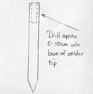
Ray notes that it should be mm not cm


Bill,

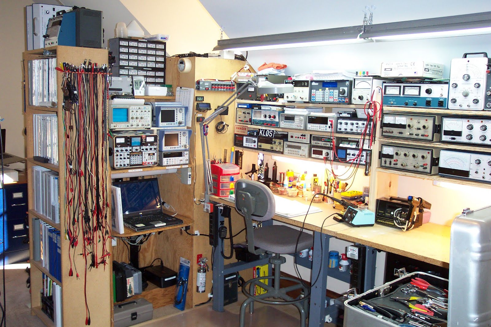
I heard you discussing the gadgets that you have in your shack on a recent SolderSmoke podcast particularly the small flame device that you use to remove the enamel from copper wire. I have found the following to be a fantastic way to remove the enamel and tin the wire at the same time. I was alerted to this process by Grant, VK4JAZ, who saw it on the Hendricks QRP Kits site.

Get hold of a basic soldering iron, usually around $10 - $20, and take out the solder tip (you don't need to buy a new iron if you have a spare tip but I find the separate iron allows me more flexibility during construction). Drill a hole in the base of the tip, about 5 - 10 mm, and place the tip point first into the soldering iron. The hole can be filled with solder when the iron is hot and all you do is put the enameled wire into the solder. The heat removes the enamel and the wire is tinned at the same time. The burnt enamel floats to the surface and all you need to do is skim it off before tinning another wire: Simple and neat.

Vy --... ...--,

de Ray VK4ZW

Our book: "SolderSmoke -- Global Adventures in Wireless Electronics"http://soldersmoke.com/book.htmOur coffee mugs, T-Shirts, bumper stickers: http://www.cafepress.com/SolderSmokeOur Book Store: http://astore.amazon.com/contracross-20

Sunday, February 19, 2012

Words of Wisdom from Farhan

I read the mail of the BITX20 group. Here is some good advice from Farhan:

I have often seen builders finishing an entire build, then powering it
up to face the frustration of a dead circuit. I suspect that the
trouble is with our kit building mind set. As a kit builder, we assume
that if it has worked well for a few hundred others, there is no
reason for it to not work for us. But the truth is more sobering ...
Of the hundred odd components, any of them could get swapped by
another, or a bad solder, wrong polarity, etc. can all conspire to
thwart your attempts. The bitx manuals are really some of the best
produced in the recent years and yet, even with leonard's videos,
troubleshooting kits is a challenge.
I am proposing a more elaborate, slower but surer approach to building the bitx.

It is as follows: build it one stage at a time, use one stage to test
the next. For instance, one could start with the bfo first. Just a
single transistor with the crystal. Then use an RF probe to check the
rf output. If there is no output, then sort that out before proceeding
to the next stage. With the addition of the buffer amp, the output
should go up. Then one could proceed to the audio amp. Injecting audio
from your mp3 player or computer could check that it works. Next,
replace the audio source with the mic amp, this tests the mic amp.
Now, if you add the two diode modulator, you should be able to receive
the dsb at 10 MHz on your HF transceiver.

This approach tests each stage individually and in isolation before
proceeding to the next. It also provides wholesome education to the
builder. In software industry, it is called a 'test driven
development' method of developing software.

In the end, this approach is no slower than the current approach,
except that surprises are not kept for the last.

I am sure that some of us can come out with a sequence of stages to
build where each stage is tested using the previous stage.

As much as bitx is about building it cheap, it is also about learning
your radio from inside. Bitx is also education on the cheap, don't
give up that opportunity.

- farhan VU2ESE

Our book: "SolderSmoke -- Global Adventures in Wireless Electronics"http://soldersmoke.com/book.htmOur coffee mugs, T-Shirts, bumper stickers: http://www.cafepress.com/SolderSmokeOur Book Store: http://astore.amazon.com/contracross-20
Designer: Douglas Bowman | Dimodifikasi oleh Abdul Munir Original Posting Rounders 3 Column