The work of Ken G4IIB has been on this blog before -- he helped many of us make use of the amazing RTL-SDR Dongle SDR receivers. He has recently turned his attention to the BITX40 Module and offers some great ideas for testing and for modification. Ken's description of the smoothness of his audio adds a very evocative term to the SolderSmoke Enhanced SSB lexicon.
Hi Bill, Pete
Many thanks for your respective responses to my plea for help in setting up
SI5351 derived BFO to my BITX40 board. You were both on the money.
Pete suggested that I had too much gain in my HB amplifier from the SI5351
output to the modulator and indeed that proved to be true. Once sorted I also
noted that I was getting extra hiss on switching to one of the sidebands as you
pointed out Bill this proved to be due to incorrect placement of that particular
BFO frequency.
These BITX40 boards that Ash Farhan has developed and released to the world
wide community of Radio Amateurs are worth every penny. Because they are so
hackable (not just the circuitry but now the Raduino code also) it means that
you can tailor it to your specific specification and in the process you are
likely to learn new stuff and make new friends. I describe my BITX40
incarnation and experiences below:
Upon first firing up the BITX I was getting quite a lot of mains hum from my
PSU's (I thought that at least one of these PSU's was a quality item) but
obviously not up to the job. I constructed a simple one transistor capacitor
multiplier (this converted a humble 1000uF cap into a 1F cap) and the noise
magically disappeared. By coincidence I note that Bill discussed this technique
in a recent pod cast. Another advantage of this technique was that I got a 2V
drop across the transistor so by running this on 13.8V I get 12V out so I run
the PA section on un-smoothed 13.8V (this gives me 12 watts of RF out) and run
the receiver section on the smoothed 12V output from the multiplier, happy
days.
My thoughts were to turn my BITX into a multi band (several bands rather than
all bands) rig and I figured that using high side mixing (running the VFO at
19Mhz (12Mhz + 7 Mhz) rather than the existing low side mixing (12Mhz -
7Mhz=5Mhz VFO)) would be a better option. For example running it on 17M would
mean using high side VFO anyway. I also wanted the ability to be able to switch
sidebands especially on the lower frequencies so that I could use the rig for
Digital modes in my case this was to be achieved by coding the Arduino to run a
BFO on one of the SI5351's clk ports.
I bought my BITX prior to the release of the Raduino so I had already commenced
(with the aid of a new found radio friend and RF mentor) coding an Arduino
VFO/BFO using a UNO and SI5351. Like I said at the beginning once you let folk
know that you are starting on a new and interesting project you start to engage
the more practical members of the ham community and they just want to get
involved and help. Yet another good reason to buy a BITX . We used code
originally developed by Jason Mildrum NT7S and Przemek Sadowski SQ9NJE and
tailored it to suit the BITX40 and our requirements. This include high side VFO
with frequency step adjustment and a BFO with long push BFO changeover. This
meant that my BITX front panel should stay very minimalistic 2 knobs.
Getting the VFO to work was simple as the DDS socket was used and to better
accommodate the high side VFO I modified the board by tombstoning caps C91
& C92.
Getting the BFO to work proved to be more problematic I was troubled with hiss
and other noise. Words of wisdom from Pete Juliano when asked if I was doing
something wrong were: " No –it is
just that we tend to think our projects are like Lego type building blocks
where everything mates and snaps together. Sometimes more is required".
True Pete and that gives us the opportunity to learn new stuff!
To cut a long story short I found that the best place to connect the BFO was on
the modulation transformer T4 thus bypassing the BITX BFO stage altogether. I
was also getting hash noise believed to be emanating from the Uno. At this
stage my after market Raduino arrived from India. I fired this up and noticed
that I was not getting any hash noise from it. This pointed us to a coding
problem and the LCD refresh was altered on our code and the problem
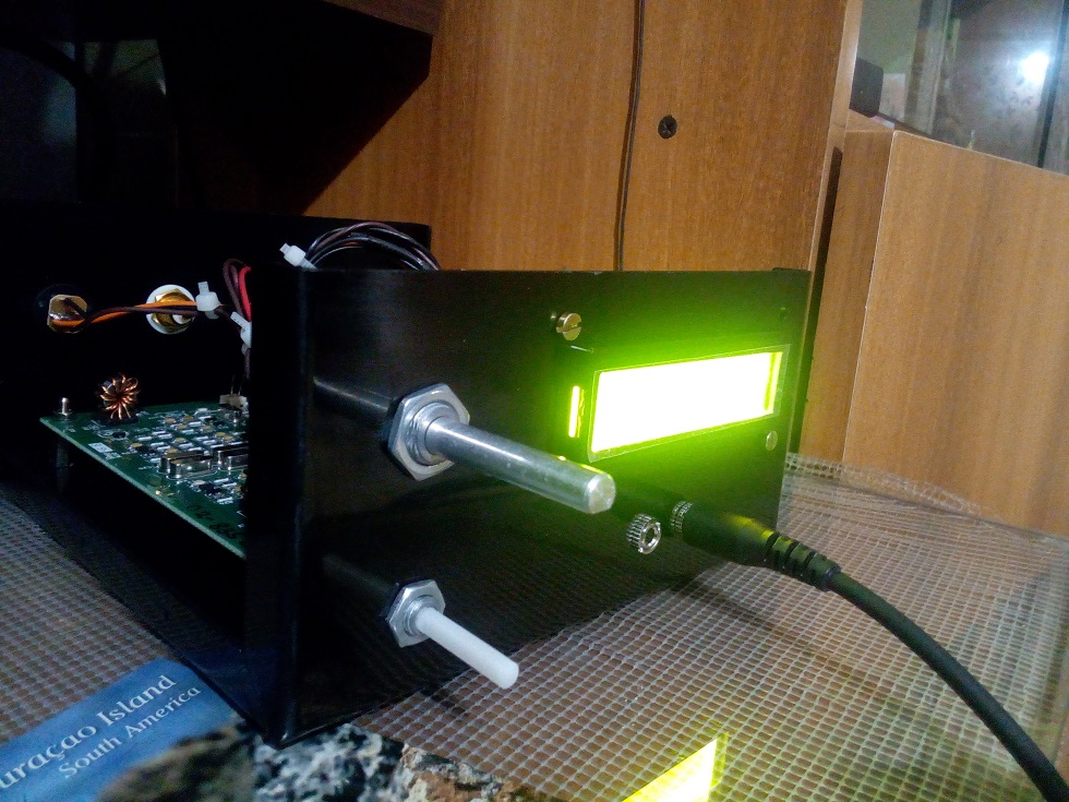
disappeared. Below a picture of the module showing the BFO connections to T4
and the large heat-sink with the IRF510 insulated from it. Also shown is the
capacitor multiplier and a glimpse of the Raduino in the foreground. Not the
most elegant box but this is likely to change pending further refinements. It's
still work in progress and this box gives me plenty of room.

The Raduino is a fantastic piece of kit for the money extremely neat and well
thought out. The coding is comprehensive and innovative and works well.
However, from an aesthetic and ergonomic point of view there were a few things
that I personally did not like in terms of how it operates and performs. I
could not get away with the potentiometer tuning, you can tune 50Khz of the
band and then when you near the pot edge it increments/decrements and you can
re-tune. I found this clunky to use and in addition the Raduino would hunt
causing the last digit to increment then decrement causing an annoying warble
on audio. In my opinion a Rotary Encoder would be better solution. On the plus
side, although not mentioned on the Hfsigs web site the Raduino code does come
with other functions such as changing sidebands by temporary high siding the
mixer, a RIT, VFO B and CW tone. If you download and read the Raduino code from
Github you will see this extra functionality which I believe you can make use
of via extra switches (not supplied). The current Raduino code does not have
any external BFO options as said it relies on the crystal BFO and temporally
high siding the VFO to change from LSB to USB on 7Mhz.
The Raduino module itself is just too good and neat not to use. As I did not
have the where for all to fully understand and amend Ash's code I decided to
use the Raduino but to load it with the code that we have developed for he Uno
and Addafruit SI5351 board. This would give me near conventional tuning via a
rotary encoder, adjustable step sizes via quick push of the encoder switch and
USB/ LSB switching via long push of the encoder switch by virtue of the SI5351
generating the BFO frequency. I have retained a copy of Ash's Raduino code just
in case I wish to revert to it. I put a new header on the Raduino P3 connector
so that I could connect a rotary encoder and use the 2nd clock output and then
changed our code to run on a Nano. I had to add a correction factor in the code
to cater for calibration differences in the SI5351's (in my case 1.21Khz).
As previously indicated I had a little trouble arriving at the correct BFO
frequencies I found that 119940 and 119970 gave me LSB and USB respectively for
my high side VFO (19Mhz) if you use low side VFO (5Mhz) then these would be
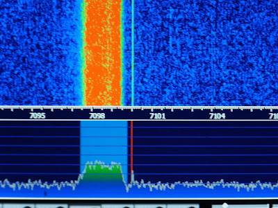
reversed. We further refined these frequencies by injecting white noise into
the mic amp and looked at each transmitted sideband on my RTL-SDR dongle via
HDSDR (a useful piece of test equipment). By adjusting the carrier trimmer to
show the carrier in the extended HDSDR spectrum display we could see how much
to move the BFO frequency to best occupy the crystal filter pass band, see
image below. This frequency adjustment being achieved by a coding change. The
frequencies I consolidated on to cater for my particular crystal filter are
119941 LSB and 119969 USB. We then nulled the carrier back out. My audio is now
as smooth as a maiden's inner thigh, trust me the image will follow!
So now I can get on and build an AGC and
think about some sort of S meter. As for putting the BITX on other bands,
whilst I now have a VFO capable of going anywhere, I would need to address band
pass and low pass filter and switching arrangements. I may still experiment
with this but, as pointed out by Ash in a recent pod-cast, the BITX single
superhet design is not best suited to multi band operation but can be quite
easily changed to operate on another single band. He also indicated that he was
developing a dual superhet with consideration for multi band operation. Once
released this might be a better option for multi-band use.
In the mean time folk should just get a BITX40, hack it to bits and share with
us their customised versions.
Ken G4IIB