


Wednesday, July 3, 2019
Building Spark-Gap Transmitters -- And a Very Cool Coherer (video)
The creators of "Plasma" and "Blueprint" YouTube channels have collaborated on this very interesting video about spark-gap radio transmitters and receivers. Really nice work. Especially impressive was the coherer build by Blueprint. I detect the spirit of Nikola Tesla in his lab!
Tuesday, July 2, 2019
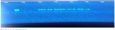
LightSail 2 -- Solar Sailing Cubesat with a Beacon on the 70cm Band
Once deployed, LightSail 2 will automatically transmit a beacon packet every few seconds, which can be decoded into 238 lines of text telemetry describing the spacecraft's health and status, including everything from battery status to solar sail deployment motor state. Every 45 seconds, the spacecraft will transmit "LS2" on the spacecraft's frequency of 437.025 MHz, within the Amateur Radio 70-centimeter band.
Further details can be found online at,
http://www.planetary.org/explore/projects/lightsail-solar-sailing/

http://www.planetary.org/explore/projects/lightsail-solar-sailing/

Saturday, June 29, 2019
Caption (or meme) Contest!

Please supply a caption for this picture. Or turn it into a meme.
Place submissions in the comments section below (or e-mail them in)
Feel free to use the hosts of the SolderSmoke podcast.
Antuino's Cubesat Origins, and How it Works (with video)
Farhan's Antuino Page: http://www.hfsignals.com/index.php/antuino/
Dec 27, 2018 to BITX.io
peeps,
while trying to measure the swr on the cubesats, i figured i couldnt use any of the analyzers i had access to. they were simply too big to be stuffed inside a 10 cm cube. my simple resistive bridge was too insensitive for any reasonable work. so, i sat down and made an antenna analyzer from a spare raduino.
the code is wobbly and just about enough to get my work done. it works on a superhet principle. this is not my clever idea, rahul had mentioned this approach taken by a russian builder. i havent seen the original design. it would be interesting if rahul or someone can point me in the right direction.
the code and a pdf of the circuit is on https://github.com/afarhan/antuino. i am attaching the circuit for the lazy bones.
have a great holiday and get some dx !!
- f


Dec 28 2018
Jerry,
first, thanks. there is substantially your code in there.
second, onto the circuit. it uses two clocks. not three. the third is a spare output. more on that later.
the circuit here uses a resistive return loss bridge. the clock 1 drives the bridge through the R22 to a low level of -10dbm. If the bridge is perfectly balanced (that is, the antenna, R21, R29, R16, all the four are the same ohms), then, there will be no RF developed across pins 3 and 4 of the ADE mixer. Under ideal match conditions, there is no RF across the R26. As the mismatch increases, so does the RF across R26.
We could directly detect the voltage across the R26 with a diode detector. This is quite a popular configuration with most of the simple resistive kind of SWR bridges (like the one designed by Dan Tayloe). This simplicity comes at a cost. The problem is that the detector responds to all the RF between the arms. For instance, if another ham down the block starts to transmit, that energy will show up across the R26 and you will get crazy SWR. I had that problem with broadcast FM showing up on my 7 MHz dipole! Even if there was no RFI from elsewhere, harmonics and spurs from your own transmission can show false readings.
Here is an example: a 7 MHz transmitter with a 14 Mhz harmonic that is 20 db down is connected to a 7 MHz dipole. The dipole is perfectly tuned to show 1:1 SWR, hence, it should show no RF across R26. However, as the antenna is reflecting back the 14 MHz energy, the 14 MHz shows up across the R26.
What's the solution to get a clean dip?The solution is to substitute a simple detector like a diode detector with a simple receiver that is tuned exactly to the frequency that you want to measure the antenna at.
So, the ADE-1 mixer, Q2, Q1 together form a very simple superhet receiver with 25 MHz IF andCLK2 as the local oscillator. The RF at the IF is directly detected and converted to db range with the AD8307. This simple configuration makes this a very powerful instrument.
Here are things you can do with it:
1. Switch off the CLK1, now you have a receiver that can very accurately measure RF levels at any specific frequency in db range. For instance, you connected your transmitter with a suitable RF attenuator to P3, you can tune to various harmonics and measure them very accurately. If you inject a two tone signal into an amplifier, you could easily measure the IMD and IIP3.
2. With the CLK1 on, the instrument now measures the return loss. you can measure the SWR of an antenna, S11 parameters of an amplifier, filter, etc.
3. With CLK1 off, CLK 2 on, the CLK2 can now tune to the frequency tuned in by the receiver's LO (CLK0). By connecting a device/filter between P3 and P4, you can sweep it to measure the gain, frequency reponse.
4. As the diode mixer (ADE-1) has harmonic response, a local oscillator at 135 MHz, will also convert a 430 MHz signal into 25 MHz IF (430 - (135 x 3)). This is possible because we are driving the diode mixer with a square wave from the Si5351 and the local oscillator at 135 MHz also has a 405 Mhz harmonic in it. Hence, the range of this instrument extends to UHF.
The ADE-1 mixer is quite similar to the ubitx mixers. You could even use ubitx kind of discrete version of a diode mixer, it doesn't work too well beyond 50 MHz. The pins 4 and 3 of the ADE-1 are the primary winding of the RF-input side transformer. The documentation recommends that we must ground 4, but that is not essential. We need a differential drive between those two pins, that is what the bridge provides anyway.
73, f
jerry,
i built it so i could stuff it inside the cubesat to measure the antenna. an external spectrum analyzer and its cables were upsetting the RF model hence, i needed something that could read the return loss sitting inside the cubesat. then, i borrowed by daughter's DSLR with a monsterous tele lens and sat 100 meters away to read the the LCD display as it swept through the range.
the analyzer was removed once we knew the correct dimensions and the actual payload went inside the bird.
- f
Monday, June 24, 2019
Mike KL7R's Web site on Way Back Machine
Thanks to Karl K5KHK for digging this up. Excellent. Three cheers for the WayBack Machine.
And thanks again to Walt K3ASW for voicing concern about the disappearance of Mike's site. Good to know that all is not lost.
https://web.archive.org/web/20131126190933/http://kl7r.ham-radio.ch/
And thanks again to Walt K3ASW for voicing concern about the disappearance of Mike's site. Good to know that all is not lost.
https://web.archive.org/web/20131126190933/http://kl7r.ham-radio.ch/
Pete N6QW's RADIG SDR On The Air!

Hi Bill:
So far I have made about two dozen contacts with the new RADIG. Just finished one with a ham I know in New Mexico and he is an RF Engineer –he was a designer at Alpha. I asked that he do a critical review of how I sounded and looked on his SDR – a good report and his comment was that if I hadn’t told him he would have guessed it was a $4 or $5K box.
So another goal achieved –on my 60th year anniversary and this makes #37.
Saturday, June 22, 2019
SolderSmoke Podcast #212 HDR, Boatanchors, SDR, Antuinos, Spurs, QSX, Mailbag
 |
| Dale Parfitt W4OP's SBE-33 with modern digi freq counter |
http://soldersmoke.com/soldersmoke212.mp3
22 June 2019
CONGRATULATIONS TO PETE: Licensed 60 years today
 |
| Pete Juliano during Field Day, 1959 |
Hans's QSX SDR Rig at Dayton-Xenia and FDIM
W8SX FDIM interviews
Pete's SDR Projects -- Update
The Peregrino SSB transceiver in the summer SPRAT
Why no rare earth cell phone speakers in ham projects?
My HDR "waterfall" project
Farhan's Antuino
Cubesat origins
RF Lab in an box
SWR, PWR, SNA
Superhet receiver with ADE-1 at front, and log IC at the output
Adapters (SMA to BNC) help
DON'T BLOW UP THE INPUT RESISTORS (LIKE I DID!)
My dirty DIGITIA -- Denial, then acceptance
FFT
Useful programs: SPURTUNE and ELSIE
A better bandpass filter for the DIGITIA
The importance of a good test set up with Antuino
Manassas Hamfest: WA1UQO, W4WIN, AI4OT
MAILBAG:
KG7SSB
WA3EIB
VK4PG
W3BBO
Jeff Tucker -- Who owns Drake 2-B #4215?
KN4BXI
KC5RT
K3ASW
Subscribe to:
Posts (Atom)


