Podcasting since 2005! Listen to Latest SolderSmoke

Tuesday, March 1, 2022

Dennis WC8C's FB Homebrew 6 Meter Rig -- Any Ideas or Suggestions?

 
Dennis WC8C is the event coordinator for the radio club in Michigan that I recently spoke with.  He mentioned to me that he was working on a homebrew 6 meter rig.  FB Dennis.  I see lots of tribal wisdom in your approach, especially in your decision to do this in a stage-by-stage modular form. 
Dennis's rig is obviously a work in progress, so if anyone out there has any helpful hints (especially on the carrier suppression and on the testing for spurs and splatter) please share them with him via e-mail or blog post.  

The files on Dennis's rig are on GITHUB: https://github.com/soligen2010/6_Meter_Transceiver

Thanks Dennis!  
----------------

This is my 6 Meter homebrew transceiver, currently work in progress.  It is a single conversion super –heterodyne design.  I constructed each stage independently with SMA connectors.  This is so I can re-make sections as needed, and will allow me in the future to swap sections to experiment with alternate designs.  The VFO and BFO are controlled using a SI5351 with an Arduino micro controller.  I currently have separate SI5351 modules for VFO and BFO because I suspected issues with cross-talk.  These issues may not actually be real, so once I am happy with the performance, I will test again with just one module to see if it is OK.  The Power Amp is still on the to-do list, so output is well under 0 DBm

The Blue boards were designed by me and ordered on-line.  The other boards I etched myself.  Construction is mostly surface mount because I find it easier than drilling all the holes.  SMD components are mostly 805 and 1206 size. Transistors are SOT23.

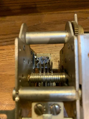
The Band Pass filter is a 5 coil design made with air-core inductors.

3 bi-directional termination insensitive (TIA) amps are used (blue boards).  Total RX gain is about 44db.  Total TX gain is about 16db.  Each board has its own independent RX/TX switching circuitry (mosfet based) and is fed with +12.5, GND, and RX/TX logic signal from the Arduino (3V logic and up will work)

The Mixer and modulator are both Diode Ring mixers.

The 12 MHz SSB filter is a crystal ladder filter similar to the one used in the uBitx.

The Mic and audio pre-amp (also a blue board) is made on a modified TIA amp board.  I had 10 of these boards made, and the needed circuitry was largely the same, so I modified the board with a rotary tool and jumpers.

The Audio amp is a PAM8403 module and drives a headset.  I did make some modifications to the module so it runs in-spec and to eliminate the power on audio pop.

The challenges I have been having are mostly related to spurs, splatter, carrier suppression and TX audio quality.  I have been gradually tweaking these things to improve operation before I start on a power amp.  My IF is 12 MHZ, and I was using the LSB side of the crystal filter because it is sharper (VFO 62 – 66 MHz) but have recently changed over to the USB side of the filter (VFO 38 – 42 MHz).  This eliminated the spurs I was seeing near the pass band.  I still need to make some adjustments to the crystal filter as it is too broad.

I still have some splatter and audio quality seems low, but I am starting to doubt my test setup.  I see the splatter on the RTL SDR, but I don’t see it on the Tiny SA.  The spatter happens at ~160 KHz intervals.  I am hoping to find someone local with a better spectrum analyzer to help me verify if it is the rig or my SDR dongle/test setup.

The modules to the side of the picture are my rejects/experiments.  The one covered in copper shows how I eventually will shield all the modules.  I 3D printed a cover for the board, when wrapped it with copper tape, soldered to the bottom ground plane.  The one shown is a diode ring modulator.  For some unknown reason the carrier suppression is rather poor.  I had previously made a junk-box modulator that had much better carrier suppression.  I don’t know why it is better than the one I more carefully made for the radio, but until I figure it out, I am using the junk box version.  The junk box modulator uses unmatched schottkey diodes, whereas the “final” one uses a 4 diode SMD package because I wanted them matched – I thought this would be better, but maybe not.

Monday, February 28, 2022

Free Download of AADE Filter Design Software

Very useful when homebrewing filters. I am using it now to build crystal filters.  

http://www.ke5fx.com/aadeflt.htm

Thanks to KE5FX


LA6NCA Designs and Builds a Very Hybrid 80 Meter Transmitter (Si5351 and a 12A6 Tube) (Video)


Helge LA6NCA put out a really nice video explaining how he designed and built an 80 meter transmitter. 

I like how he put the Si5351 and the Arduino chip in what looks like a slightly expanded FT-241 crystal box.  Nice.  

I like the box and the chassis.  

I like his testing/tuning technique.  

The homebrew capacitor was a very nice touch.  

Where can I get some of those coil forms?  

And of course, the R-390 receiver adds a lot of mojo to the shack. 

Helge's web sites document an enormous number of great projects:  

Helge's page on the 12A6/Si5351 transmitter: https://www.la6nca.net/homebrew/tx_12a6/index.htm


Thank you Helge! And thanks to Hack-A-Day for alerting us to this. 

Sunday, February 27, 2022

VK3HN's Amazing Summit Prowler 9 Homebrew Transceiver - A Masterpiece of Miniaturization (VIDEO)


I was wondering what Paul VK3HN was up to. Now we know: the Summit Prowler 9 transceiver. 

This is yet another amazing rig by Paul, with GREAT documentation.   

I was impressed by those bandpass filters.  I will try to do something similarly robust on my 17/12 rig. 

Paul's miniaturization of this rig is really astonishing.  I would go nuts trying to keep it this small. I just couldn't do it. 

Look closely at the boards he uses.  They look like printed circuit boards, but with all the components and all the soldering on one side.  This is very smart -- this makes it easier to troubleshoot and to change components.  

I was glad to see at least one NE-602 in there.  FB. 

The video is above.  Check out Paul's blog for more info: 


Thanks Paul!

Friday, February 25, 2022

Split Stator Temperature Compensation Also Used in Yaesu FT-101


The eagle eye of VE3EAC spotted this (he also correctly pointed to a tiny broken "tine" as the cause of my  HP8640B woes).   I had missed the temp comp circuit.  Inside the Yaesu FT-101 VFO box that I used in my Mythbuster rig, there is a split stator capacitor and two temperature compensation caps similar to that recently described by Mike WU2D.  Very cool.  You can see the temp compensation cap in the picture (above). The red arrow points to the split stator cap,  the blue arrow points to to the two temperature compensation caps attached to it. You can see them all in the schematic below(in the lower left of the schematic). 

Thursday, February 24, 2022

Old Military Radios at the Air and Space Museum Udvar-Hazy Center, and Autogyros

 
My son Bill and I were out at the National Air and Space Museum's Udvar-Hazy Center (out near Dulles Airport, where they display the really big stuff).  We spotted these old military radios.  The ARC-5 Command sets caught my eye.  Of course I was thinking about the great VFO parts inside those boxes...   The acknowledgement of the ARC-5's contribution to ham radio (on the card) was nice. 

 They also have an ART-13 on display.  


We had a lot of fun looking at all the planes.  We were especially impressed by the Autogyros. 
The Bensen B-6 Gyroglider seemed to be really pushing the envelope (of good sense!).   This was a an Autogyro with NO MOTOR.  It was towed!  No license required as long as you didn't release the tow line.   Note that it was designed in 1954 to introduce teenagers "to the thrills of flight at minimal cost." The headgear and goggles were key.  And the kit was only $100! 


Wednesday, February 23, 2022

An Analog LC VFO for my 17/12 Meter SSB Transceiver (VIDEO #1)


Here's my initial work on a VFO for my 17 meter -- 12 Meter Single Conversion Dual Band SSB Transceiver. The IF (crystal filter) will be at 21.4772 MHz. On 12 meters the VFO will run from 3.5128 to 3.4528 MHz. On 17 the VFO will run from 3.3092 to 3.3672 MHz.

The transistor I am using is an SK3050 Dual Gate MOSFET. I bought a bunch of these years ago in a panic when I heard that 40673's were getting scarce.

I forgot to mention another important reference: Joe Carr's Popular Electronics VFO articles:

Thanks again to Dale K9NN for the bags of NP0 capacitors. And to Pete N6QW for the suggestion on the HT-37 main tuning cap.   Thanks to Mike WU2D for the great VFO videos, and to Frank Harris for his wonderful book on homebrewing.  And we can't forget the great reference books that guide so many of our projects: Solid State Design for the Radio Amateur and Experimental Methods in RF Design -- thanks to Wes Hayward W7ZOI and all of his co-authors.  

Saturday, February 19, 2022

Pete's Eclectic Approach to the Pea Shooter, San Jian counters on Analog VFOs, Non-Restaurant Menus

I liked Pete's comments on the various (analog, digital, mixed) approaches to homebrew: 

http://n6qw.blogspot.com/2022/02/2022-return-to-peashooter-build.html

http://n6qw.blogspot.com/2022/02/2022-peashooter-20m-compact-ssb.html

I too have San Jian digital counters watching the stability of analog VFOs (DX-100, HQ-100, Mythbuster). 

Variety is the spice of life!  

I also liked Pete's comment about the fellow who does on-the-air menu counseling for FTDX-3000 owners.  I sometimes run into guys on the air who want to do something similar with my simple homebrew rigs.  They start by making comments about my audio -- they will usually say it is "too high" or something like that.  Especially when I'm using the separate transmitter and receiver (which have to be "netted" imprecisely by ear), I have to explain that maybe resort to their RIT control would help.  If they persist, I sometimes have to tell them that how my rig sounds depends A LOT on the placement of the carrier oscillator relative to the passband of the crystal filter (most recently, the filter from the 1963 Swan 240).  Most of them have never had to do that kind of adjustment, so the "technical discussion" usually ends at that point, with my interlocutor saying 73, and presumably moving on to someone whose rig has menus to fiddle with.  (Recently heard audio techno term: "massaging the codec.") 

To each his own!    


Friday, February 18, 2022

Tuesday, February 15, 2022

Differential Temperature Compensation Capacitors in the Hallicrafters HT-37 Main VFO Tuning Circuit

 
I've been watching with great interest Mike WU2D's excellent series on VFO construction.  His second video is especially interesting because he talks about how we can use a split stator differential capacitor to build a temperature compensation circuit that will allow us to "dial in" the proper amount of temperature compensation.  

The heart of this circuit is the split stator differential capacitor.  The stator is split; but there is a common rotator. As the rotator moves, the capacity across one part of the capacitor increases while the other part decreases -- thus the total capacity remains unchanged.  If we connect two capacitors of the same capacitance BUT OF OPPOSITE TEMPERATURE CHARACTERISTICS -- we can use this split stator cap to select just the right amount of temperature compensation.   Very cool.  Even cooler:  Mike actually built a split stator differential capacitor.  That, my friends, is dedication. 

I was sitting here this morning thinking about all this when it occurred to me that right in front of me was a capacitor that might be relevant to all this (see above).  I bought it on e-bay one year ago after Pete N6QW had alerted me to it.  It is the main tuning capacitor from an HT-37 transmitter.  What attracted us was the big anti-backlash mechanism.  But now I realized that it had another charming feature.  

Looking at it a bit more closely I saw a split stator differential cap just like the one that Mike had made.  Attached to the two rotors were two tubular capacitors.  The three caps are in parallel with the main tuning cap.  Bingo -- this is a temp compensation circuit.  

I checked the HT-37 manual.  The manual says that temp compensation is set at the factory.  OK.  But the schematic does not show the split stator caps and the two tubular caps (see below).  Could it have been that this circuit was added later perhaps to address drift? (We do see it in the HT-32B schematic -- see below.)

HT-37 VFO SCHEMATIC

Anyway, it was very cool to find this example of the circuit Mike was discussing.  In the photo at the beginning of this post you can see the three caps.  Below you can see the split stator cap in the background. 


In the comments a reader points out correctly that this circuit was discussed in the ARRL book "Single Sideband for the Radio Amateur."  Indeed, it is on page 51 of the 1970 edition, ARRL  gave credit for the circuit to Hallicrafters: 


HT-32B VFO Circuit

Joe Carr K4IPV (SK) also discussed this circuit.  In his article in Popular Electronics in August 1993, he too gave credit to Hallicrafters.  Carr also gave some detailed instructions on how to use the circuit to stabilize a VFO.  See pages 78 and  79 of the August 1993 Poptronics: 

Designer: Douglas Bowman | Dimodifikasi oleh Abdul Munir Original Posting Rounders 3 Column