Dear Bill:
I had never built a PTO, but after reading Farhan's Daylight Again
Transceiver article I cobbled one together with parts and pieces I
had on hand. My observations so far are as follows.
1. The frequency-determining capacitors (shown on the schematic
as three 470 pf) are very critical, so I feel the usual experimental cut-and-try
technique is a must, even using all NP0 and C0G types.
2. After I built the 2 MHz version like the article (see first photo), the stability was terrific,
but when I tried building the companion Daylight Again crystal filter,
I was only able to get a bandwidth of 1.6 kHz, which is too narrow for my taste
in an SSB radio, so I decided to build the same filter design but with 11 MHz crystals,
where I could easily achieve a 2.8 KHz BW.
3. Therefore, now I needed a higher frequency VFO, so I merely
reduced the capacitance (from about 1200 to 370 pf) without changing
the coil and I am very impressed with the performance of my 4 MHz PTO (see second photo).
The bandspread easily covers the entire 40M band, CW and Phone.
4. However, whenever I transmit on the 40M Phone band, I like to first set my VFO
within 10 Hz of the operating frequency. That way, if I talk for five minutes or
so and get up to 15 Hz of drift (which is quite common with many radios when
I operate portable outdoors in the sun and wind), it will not be noticable and I avoid
receiving any "you are off-frequency" chastising.
But the shortcoming I have with this PTO inductor is that the 1/4-20 bolt has a coarse thread,
so it is very difficult for an old fellow like me to get within even 20 Hz of a particular frequency
just using this common bolt.
Therefore I believe a better choice would be the fine thread 1/4-28 two-inch brass threaded
bolt which is available from industrial supply houses like McMaster-Carr.
However, for CW use or those with a very steady hand, the 1/4-20 works well enough.
5. I solved my fine tuning problem by adding a varactor circuit using a common
1N914 diode in series with a 100 pf capacitor, operating from 0 to 6 volts.
Another advantage to adding this feature is that since I have not so far enclosed
my PTO, I can mount the varactor potentiometer several inches from the PTO so
my hand capacitance does not affect the frequency like when tuning with the
bolt.
6. An easy way to "do the math" in my case with the common Sanjian counters
is to simply create a small lookup table listing half a dozen common frequencies
and stick it on the radio.
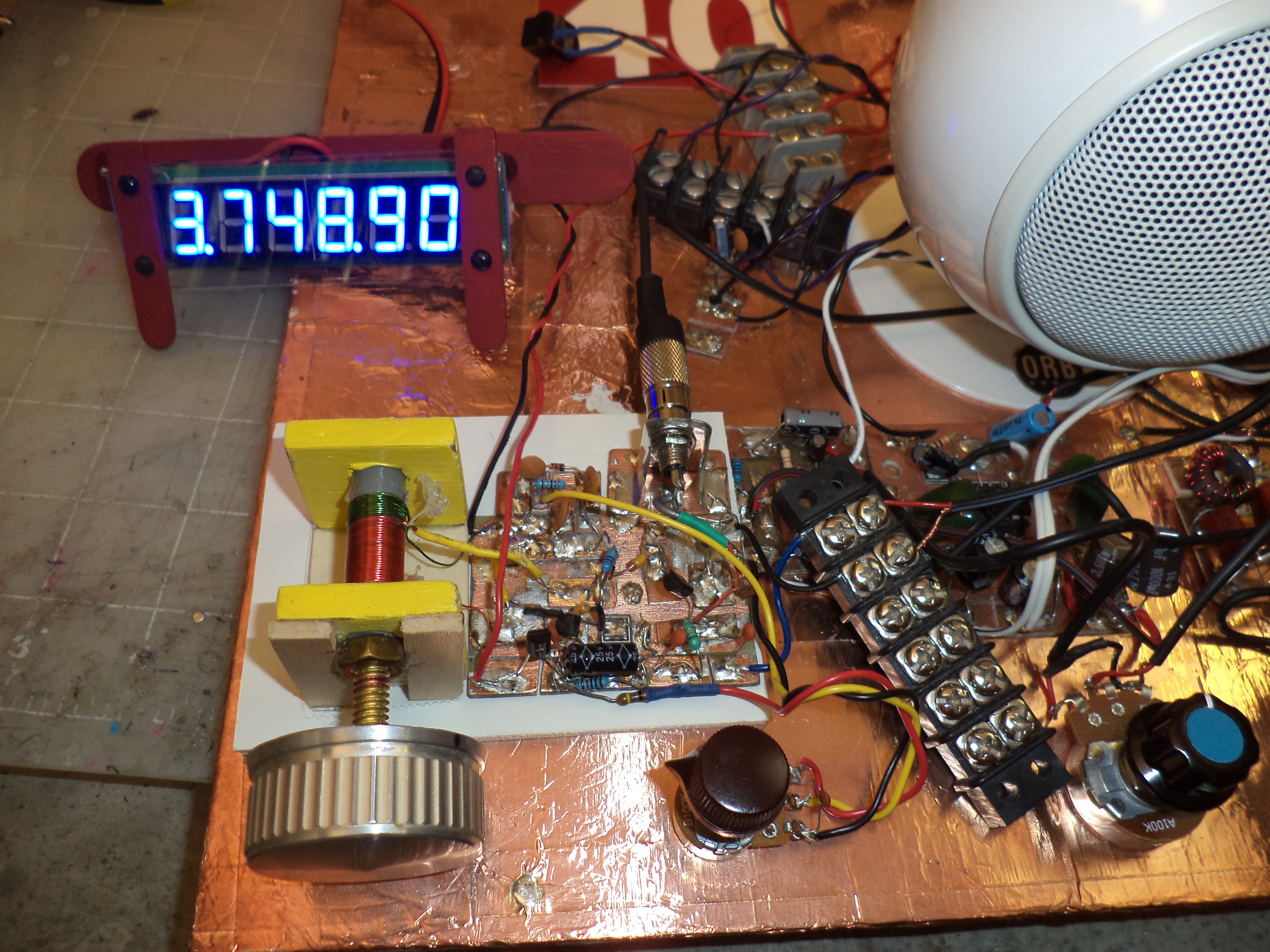
For example, 90% of the time in the morning I am tuned to my favorite SouthCars
Net frequency of 7251, so using a BFO setting of 10,999.900, I simply set
the PTO to 3,748.90 on the 6-digit 10 Hz resolution counter I normally use (see third
photo).
7. I am currently using my Daylight Again PTO on a daily basis with
an NE602 receiver, and I am thinking of adding a locknut to the bolt
so it does not wiggle when I jostle or move the radio, essentially giving me
a crystal replacement oscillator that I can use for any single 40M
frequency. To date I have been able to listen for hours at a time indoors
without even any touch-up of the varactor fine tuning.
8. Also, if continuous frequency readout is desired without building a noise filter
circuit board, a separate power supply for the counter is a solution.
For portable operation I use Lithium Polymer radio control model airplane
batteries which are light, small, and cheap, so one 12V 2000 mAH battery
for the transceiver (allows a half hour of transmitting at 15 watts)
and a much smaller 12V 350 mAH battery with a series resistor to
reduce the current and brightness of the counter has worked well for me.
73,
Walter
KA4KXX