Podcasting since 2005! Listen to Latest SolderSmoke

Showing posts with label Swan 240. Show all posts

Monday, January 10, 2022

Exorcism Not Quite Complete -- Thinking of Other Options

As often happens, I may have jumped the gun in declaring the exorcism of my 17 meter transmitter to be a success. As readers of this blog will recall, my problem was that when trying to "net" my separate 17 MHz receiver and transmitter, at around 18.116 MHz I could hear more than one tone as I tried to get to zero beat.  The 8th harmonic of my 5.176 MHz carrier oscillator was mixing with the 23 MHz VXO signal and producing a spur.  I could probably knock the level of this spur down below FCC limits, but -- and here is the problem -- I probably could never knock it down to the point that it would not be audible in the sensitive receiver that sits right next to the transmitter.  So this is really a netting problem, not really a spur problem. 

I don't want to try another filter frequency -- I have VXO crystals that really work only with a filter at 5.176 MHz.

So here is my current idea:  Build a receiver board and turn this thing into a transceiver.  Switch with relays the input and output of the 5.176 MHz filter, and use relays to switch to the receiver board the VXO and carrier oscillator signals. 

Making this thing a transceiver would eliminate the need for netting.  This should solve my problem. 

What do you folks think? 

73  Bill 

Tuesday, December 7, 2021

Junk Box Sideband from the Azores (2004 QST Article)


About 20 years after I first built it, I find myself working on and using this SSB transmitter.    I recently added some impedance matching to the Swan 240 crystal filter;  several years ago I replaced the PA with a "JBOT" amplifier designed by Farhan VU2ESE.  I now have it on the air, using it with a highly modified Doug DeMaw, Barebones "Barbados" superhet  receiver. I had my first (recent!) QSO with this station yesterday, with Les 6Y6Y on the beach in Negril, Jamaica. 

More on this project in due course. Lots of soul in this machine. 

I'd forgotten about this article -- thanks to Pete Eaton for reminding me. Click on the images for a better look at the article. For an even clearer view, download the images and then open them on your computer. 


Saturday, November 20, 2021

The Double Crystal Lattice Filter in the Swan 240 -- Smoothing it out with a NanoVNA


In SolderSmoke Podcast #234, I said that I was scrutinizing the filter from the Swan 240 that I had picked up around 1994 in the Dominican Republic.  I cannibalized it out in the Azores in the early 2000s and used the parts to build -- among other things -- my first SSB transmitter.  I never really focused much attention on the filter that I pulled out of that old rig -- I was just happy that it seemed to work. But I am now older and wiser, and I have some test gear that lets me look at the passband of that filter. 


First, take a look at what it is supposed to look like.  This is from the manual.  Yikes!  That passband looks far from flat.  I can almost hear homebrewers around the world shrieking in horror and disgust.  


Above is a description of the filter, and the schematic, again from the manual. 


Here is what my extracted and somewhat re-built filter looked like in my NanoVNA (more shrieking!).  The dip in the passband is a lot worse here -- it looks like 10 db vs. 3 db in the manual.  This is probably because I'm not even attempting any impedance matching on the filter -- it is just seeing the 50 ohms in and out of the NanoVNA. 


Here is my 2002 attempt to rebuild the filter and put it in my SSB transmitter, along with my more recent attempt to flatten the passband.  I no longer had the adjustable coil L8, so I made my own coil based on guidance from Ben Vester W3TLN's January 1959 QST article on "Surplus-Crystal High-Frequency Filters." (Ben had an early influence on Pete Juliano's tube-rig  designs.)  In the picture above I have 1k pots between the filter and the input and the output of the NanoVNA, as described by Nick M0NTV


Adjusting the 1 k pots, I could smooth out the passband quite a bit.  Measuring the pots and adding the 50 ohms of the NanoVNA, it looks to me like this filter is smoother with about 280 ohms at the input and output.  I may build two matching networks or some transformers. Some TIAs may also be needed. 

Thursday, July 22, 2021

The Unicorn! A 75 LSB /20 USB Receiver (That Can't Work)


Don't get me wrong -- I'm a huge fan of Doug DeMaw.  His books and articles are a treasure trove for ham radio homebrewers.  Also, Doug was an honest guy who admitted in the preface to his QRP book that at times he did not fully understand the circuits he was building; that kind of honesty is rare,  and is very helpful to amateurs who struggle to understand the circuits we work on.  

But everyone makes mistakes, and Doug made one in his "W1FB Design Notebook."  I present it here not as a "gotcha" effort to nitpick or sharpshoot a giant of homebrew radio, but because this error illustrates well the depth of the 75 LSB/20 USB myth, where it comes from, and how important it is to really understand sideband inversion.     Here is the mistake: 


That's just wrong.  A receiver built like this will not allow you to listen to 75 LSB and 20 USB "without changing the BFO frequency." (Am I the first one to spot this error?  Didn't anyone build this thing, only to discover that it, uh, doesn't work?)

Here's a little drawing that I think illustrates why the mythical scheme will not work: 


All confusion about sideband inversion could be avoided with the simple application of what I think we should call "The Hallas Rule"

"Sideband reversal occurs in mixing only  if the signal with the modulation is subtracted from the signal that isn't modulated."  

Be careful here:   I think some arithmetic carelessness is responsible for much of the myth. Taking the difference frequency is not enough to produce sideband inversion. Read the Hallas Rule carefully:   For sideband inversion to occur, the signal with the modulation must be subtracted FROM the signal without the modulation.
--------------------------------------------- 
About the Swan 240's SSB generation scheme: 

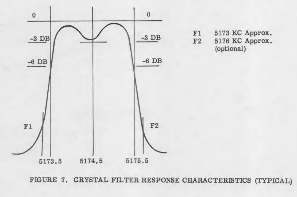
I first stumbled on this problem when building my first SSB transmitters in the Azores.  I was using a VXO,  and a filter pulled out of a Swan 240 (5.173 MHz).  I started with VXO crystals at around 12.94 MHz.  The rig worked,  but I couldn't pull the VXO crystals very far.  So I switched to crystals at around 23.3 MHz (you can pull higher frequency crystals farther).  But look what happened:  My Carrier Oscillator frequency had been set up to receive USB signals on 17 Meters.  With the 12.94 MHz rocks, that worked fine:   18.150-12.977 = NO INVERSION.  But it all changed when I went to the 23 MHz VXO rocks:  23.323-18.150 = INVERSION!   This had me scratching my head a while.  I had to draw myself little spectrum pictures (like the one above) before I realized what had happened.  To get it to work -- to get it to produce USB on 17 meters -- I had to move the Carrier Oscillator to the other side of the passband. Good thing that Swan 240 came with TWO BFO crystals (5.1768 MHz and 5.1735 MHz). I just had to change the crystal. 

For 75 and 20 meters, the Swan 240 uses the correct 5.173 MHz filter with a 9 MHz VFO to get the happy situation of 75 meter LSB and 20 Meter USB WITHOUT changing the BFO/Carrier Oscillator frequency.  This is the Mythbuster scheme.  Unlike Doug's receiver, it works.  The scheme also works in the Swan 240 on 40 meters because for 40 the Swan rig has the VFO running from 12.073 MHz to 12.513 MHz. Here too, no change in the BFO/Carrier Oscillator  frequency is needed. But the Swan recommended a modification that would allow operation on 20 LSB and 75/40 USB!  It used a BFO/Carrier Oscillator crystal of  5.1765 MHz and a switch mounted on the front panel.  Luckily,  my junker Swan (acquired from HI8P in the Dominican Republic) had the second crystal -- mine was 5.1768 MHz.  It was that crystal that allowed me to get my Azorean SSB transmitter to work using the 23.9 MHz VXO rocks.    

Designer: Douglas Bowman | Dimodifikasi oleh Abdul Munir Original Posting Rounders 3 Column