Podcasting since 2005! Listen to Latest SolderSmoke

Wednesday, March 31, 2010

SolderSmoke Podcast #123

Listen at: http://www.soldersmoke.com

SolderSmoke #123
4/1/2010
Spring! Equinox! Sap in Vermont! Aurora in Norway! Birds singing in Rome!

SolderSmoke on Oprah. Program Schedule:
http://www.soldersmoke.com/oprah.html

Special Report from MASSCON QRP Convention by Mark, NX1K

Propagation improvingWSPR as a personal sunspot detector
Building the W3PM WSPR rig
Colpitts oscillators
Polyakov's "Russian Mixer"
BANDSWEEP: A low-frequency sweep by Chris, KD4PBJ
EMRFD on Direct Conversion and Direct Aversion

Faraday's toroid diagram
NA5N's ISBN
MAILBAG

SolderSmoke--THE BOOK:
http://stores.lulu.com/store.php?fAcctID=3999032

SolderSmoke--THE STORE:
http://www.cafepress.com/SolderSmoke

Tuesday, March 30, 2010

AA1TJ on Polyakov, Scrounging Parts from a Wehrmacht Tank, QRPp Success

Caro Bill, FB on your 20mW DSB WSPR DX! I've never actually been on the air during the upside of a solar cycle. This is wicked exciting! Thank you for the nice write-up on your Soldersmoke Blog, OM. I heard back from Fabio this morning; he seems to be as excited as I am (please see his message below). Italy is my fourth DX contact and third country with 10mW. Two weeks ago I worked F5NBX twice and FM5LD once. Again, all great fun... I'm glad to hear of your interest in the Vladimir Polyakov's mixer. I can attest to Vlad's claim about its resistance to SWBCI. So far, I've used silicon and germanium diodes, MOSFETS, and even a saturating inductor for the subharmonic, commutating switches. I haven't mentioned it till now, but leading up to my Gigi regenerodyne receiver, I built Polyakov reflexed 40m receiver that was lots of fun. The RF input signal first passed through a simple BPF on its way to the cathode of a triode, grounded-grid RF amplifer. The amplified signal next passed through the Polyakov anti-parallel diodes. The resulting AF signal was then re-injected into the grid of the same triode (now working as a common-cathode amplifier). In typical "reflex' fashion, the same tube amplifies first at RF and again at AF. Looking at my notebook entry, I was able to "plainly hear" a 1.0uVrms signal and in a week of operation I hadn't noticed any SWBC breakthrough. Actually, the subharmonic mixer was well-known by 1976, but I'd never seen it used by hams at HF until Polyakov popularized the idea. Our Eastern European comadres took a liking to it right away but it took some time before it finally caught on in the West. By the way, I had a short email exchange with Vladimir a few months ago. I'm pleased to report he's a really nice fellow. He happened to mention that his first amateur radio transmitter was built using parts that he salvaged from an abandoned Wehrmacht tank. It seems radio components were extraordinarily hard to come by in those days. Amazing... Have fun, Bill! Mike, AA1TJ ---------- Forwarded message ---------- From: Fabio Ventrone Date: Sat, Mar 27, 2010 at 9:16 AM Subject: Re: IZ0PEC de AA1TJ/QRPp To: Michael Rainey Dear Michael, Many many compliments for your qrpp station! Really exciting to have qso in this conditions... It's actually the first time I can connect qrpp oversea... Unbelievable, something we can tell our friends forever!!! I was transmitting with 4 el antenna and something more than 100w. I will have to take back my 817 and try to call dx as you bravely did!!! Best 73 qsl Fabio de IZ0PEC 2010/3/26, Michael Rainey > Dear Fabio, > > Thank you for your patience in copying my signal on 20m CW this evening. I > had been calling DX stations for several hours but you were the only one to > answer. My homebrew rig has an output power of only 10mW (0.010 watts). The > distance between us is 8793km; nearly one million km per Watt!. The antenna > here is simply an end-fed wire. > > I am amazed that you heard my 10mW signal in Rome. It's fantastic! > > Again, thank you for patiently listening for my weak signal, OM. It would > not have been possible without your very kind efforts. > > Ciao, > Mike, AA1TJ

Sunday, March 28, 2010

Building W3PM's Colpitts Oscillator


I took a break from all the computer stuff and decided to melt some solder this weekend.

W3PM has a neat WSPR rig on his site. I decided to build at least parts of it. Today I put together the Colpitts oscillator. I really like this circuit -- it produces enough power to drive a diode ring mixer directly. Mine went together very smoothly. Sure enough, mine produces about 10 mW.

It was good to get back to solder melting. I used circular pads sent to me by Jerry NR5A. And parts sent by Jim AL7RV, and by Mike AA1TJ. EMRFD provided very useful background info on the circuit. I powered the prototype up with my Kempton Park power supply with the current limiting chip provided by Tony G4WIF. So it was a like a team effort. Thanks to all!

I'll try to get the next podcast out mid-week.

73

Saturday, March 27, 2010

Polyakov Plus! Dual-band Receiver with Subharmonic Mixer

I found it! SPRAT 110, Spring 2002, page 5. A short article by OM Rudi Burse, DK2RS. This is the variation on the Polyakov Russian Mixer that I mentioned a couple of days ago. I'd been digging through piles of books and old magazines looking for this. My wife thought I'd gone nuts. (Well, nuttier than usual, actually.) It didn't help that I responded "The Polyakov Russian sub-harmonic mixer circuit with two band application!" when she asked what I was looking for. Of course, I should have known that it was in SPRAT. It just happened that the issue with this article was piled under a lot of junk on the workbench. I really like this circuit. Ingenious. And now that I have come to understand mixers a bit better, I can appreciate this one more. Here's how I'd explain it: With the switch closed, the signal from the LO "opens" one of the diodes on the positive peak, and it opens the other diode on the negative peak. So that RF signal from the antenna is getting sampled and mixed twice each cycle of the LO. The resulting complex waveform has sum and difference frequencies of RF+2LO and RF-2LO. With the switch open, you only have one diode sampling the RF, and it opens only ONCE each LO cycle. So the complex waveform that comes out of this single diode had frequencies of RF+LO and RF-LO. This opens the possiblity of DC receivers for 80/40, 40/20, 20/10 meters, etc. I guess a key adjustment in this circuit would be getting the LO level just right. Thanks SPRAT! Thanks Rudi! Thanks Vladimir Polyakov!

You'll see in the comments attached to my last blog post that our man on the left coast, Steve Smith, gave that cute little Doug DeMaw/Vlad Polyakov receiver a name that might set American-Russian hamrelations back a bit: He called it "Vlad The Inhaler." Good one Steve! (But you might want to stay out of the diplo game!) 

Check out "SolderSmoke -- Global Adventures in Wireless Electronics" http://soldersmoke.com/book.htm

Thursday, March 25, 2010

Sunspot 1057 Doing Good Work for US!

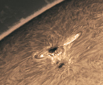
I got up early this morning, and so did 30 meters. Take a look at the WSPR signal reports that greeted me (below). My 20 mW DSB signal was making the trip to Norway and the UK through most of the night. And at 0256 W1BW picked it up. A visit to the excellent spaceweather.com website reveals that this is probably the work of sunspot 1057. Rogerio Marcon took this picture of that sunspot on March 24 from his backyard observatory in Brazil. (This and a recent thread started by Chris Trask on QRP-L make me think that I NEED a solar telescope.)

My e-mail inbox also had evidence of good HF conditions. Take a look at this from AA1TJ:

IZ0PEC de AA1TJ/QRPp

Thursday, March 25, 2010 9:52 PM
From:
To:
f.ventrone
Dear Fabio,

Thank you for your patience in copying my signal on 20m CW this evening. I had been calling DX stations for several hours but you were the only one to answer. My homebrew rig has an output power of only 10mW (0.010 watts). The distance between us is 8793km; nearly one million km per Watt!. The antenna here is simply an end-fed wire.

I am amazed that you heard my 10mW signal in Rome. It's fantastic!

Again, thank you for patiently listening for my weak signal, OM. It would not have been possible without your very kind efforts.

Ciao,
Mike, AA1TJ

Polyakov's Russian Mixer

I'm planning on building a DC receiver for use with the WSPR system. I will probably follow W3PM's lead and put a crystal filter between the antenna and the mixer. This will be a fixed frequency receiver aimed at one 200 hz slice of the 30 meter band.

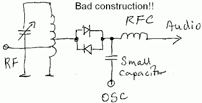
Of course, the big question is what mixer circuit I should use. I'll probably go with an SBL diode ring, but while perusing the literature, I again came across "The Russian Mixer" of Vladimir Polyakov, RA3AAE. Michael, AA1TJ, is a big fan of this circuit, and has been talking about it on Radio Havana Cuba. What a cool circuit it is! Just two diodes in parallel, cathode to anode. RF from the antenna goes in one side, and the local oscillator signal is placed at the other end. The LO signal causes the diodes to turn on and off on voltage peaks, effectively chopping up the incoming signal, producing sum and difference frequencies. LA8AK's drawing of one version of this circuit appears above. (Obviously OM AK didn't like this configuration, but it gives you the idea.)

The really cool part is that because you have two diodes, the "chopping" takes place at TWICE the LO frequency. This happens because on a positive LO peak one of the diodes conducts, and then, on the negative peak, the other conducts. So it is as if the mixer gate is opening twice each LO cycle. This allows you to run the oscillator at half the operating frequency, with advantages for stability and for the effort to eliminate common mode hum.

A while back I saw (somewhere!) a clever use of this circuit. LO was running at around 3.5 Mhz. With the two diodes in the circuit, it was a 40 meter receiver. They had a switch that could remove the second diode from the circuit. By throwing this switch, the RX went to 80 meters.

Does anyone remember this circuit? Where did it appear? SPRAT? QQ? Tech Topics? I can't find it.

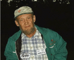
I had the impression that OM Polyakov was active in the early days of radio. But some Googling shows that he is of much more recent vintage, still active and listed on QRZ.com. Here he is:

Wednesday, March 24, 2010

Was Marconi the First Radio Amateur?


Steve, WG0AT, posed this question in the title line of his latest (excellent) video. I really liked the recordings of Marconi speaking in English. (I'd heard him in Italian, but never in English.)

So, was he one of us? I say yes. Definitely. Why? Because he very clearly had what we would call a shack. This is discussed in SolderSmoke -- The Book. When his mom saw that his tinkering with electricity had some potential (!), she had an attic room in the family home near Bologna configured as a workshop for her Knack-afflicted son. And there he tinkered. Just as we do.

Tuesday, March 23, 2010

Dino's Awesome Workbench

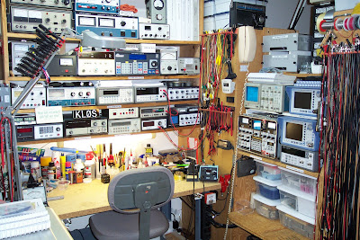
People send me these images, and they are so good that I feel compelled to put them on the blog. From Dino:
-------
Ok, can't stand it anymore....had to show off my workbench as well. BTW, will be making a presentation at Dayton Hamvention in May on "Building Your Ham Radio Workbench." So if guys have any great ideas to pass along would love to hear them and include as possible. Am gearing this toward the beginner and focusing on basics, soldering equipment, tools, safety, the bench, parts accumulation, etc. Over the past two years have made pitches at Hamvention on Test Equipment and Station Engineering Manuals....always lots of fun.
73 -- Dino KL0S

Monday, March 22, 2010

AA0MS's FB Workbench

Doug, AA0MS, sent us this nice picture of his workbench and operating position. (That looks like a nice oscilloscope!) Doug is blogging at http://aa0ms.blogspot.com/ Lots of good stuff there about his electronic adventures. I liked the pictures of the old homebrew gear that his dad built. Thanks Doug!

Sunday, March 21, 2010

The FUNKY Keyer

Paul up in Manchester has some really intriguing ideas on CW and keyers. He likes highly personalized CW from straight keys, and thinks he can even hear the influence of Latin-based languages when receiving signals from stations in France and other Romance language countries. (Like me, he also thinks a bit of homebrew chirp adds some character to signals. ) Automatic keyers seem to squeeze all of the individuality out of CW. So Paul has written some computer code to put that individuality back in! Can we get a "Lake Erie Swing" option Paul? Check out Paul's blog. Interesting stuff!

Hi Bill

Further to the kind words of introduction you gave me as a “new homebrewer” in Soldersmoke 104, I’m writing to let you know about a little project of mine which I think you might appreciate…

I made a h/b keyer a while back and recently added the ability to send automated 3*3 cq calls (and cq FISTS calls).

On doing this, I realized how much I HATE the sound of machine generated CW – so mechanical and lifeless. I want to hear a real fist – preferably with some chirp and drift thrown in for good measure!

So – I’ve come up with an alternative – The FUNKY keyer!

It adds some random timing "jitter" to each automated cq call, to simulate the sound of a real fist on a straight key.

You can read all about the Funky Keyer on my blog, http://m0xpd.blogspot.com

The blog also documents some of the other outcomes of my personal puffs of solder smoke, including the “Funster PLUS” 40m CW Transceiver and the “Not-so-superhet” experimental valve receiver. There’s some operating stuff, including WSPR on 40 and 80m with my Softrock SDR and I was inspired by Soldersmoke to include some travelog – ZL, VR2, BY, HB, etc.

Hope you enjoy it.

Let me take this opportunity to thank you for all the enthusiasm and inspiration you continue to give us in Soldersmoke,

73 de Paul, m0xpd

Paul Darlington

Saturday, March 20, 2010

Vernal Equinox!


Today marks the Vernal Equinox, an important day for QRP radio amateurs. In the Northern Hemisphere, conditions usually start to improve. And this year's equinox is accompanied by higher sunspot numbers. So cheer up guys! Better conditions are on the way.

The equinox comes at 1732 UTC today, 20 March 2010.

Spring seems to be getting off to a good radio start here in Rome. My 20 mW WSPR signal made it across the pond this morning, 8289 kilometers to W3HH (see below). This was the first signal report of the day. I only seem to cross the pond around my local dawn -- never around sunset.

Date/Time TX station SNR PWR RX Station Grid km az
2010-03-20 05:44 I0/N2CQR -7 0.02 PE1DCD JO21fu 1262 334
2010-03-20 05:44 I0/N2CQR -20 0.02 DF6DBF JO31si 1116 342
2010-03-20 05:42 I0/N2CQR -17 0.02 PE1DCD JO21fu 1262 334
2010-03-20 05:40 I0/N2CQR -15 0.02 PE1DCD JO21fu 1262 334
2010-03-20 04:40 I0/N2CQR -29 0.02 W3HH EL89 8289 296
2010-03-19 21:22 I0/N2CQR -28 0.02 LA6TPA JP54rl 2512 359
2010-03-19 21:16 I0/N2CQR -30 0.02 LA6TPA JP54rl 2512 359
2010-03-19 20:54 I0/N2CQR -29 0.02 LA6TPA JP54rl 2512 359
2010-03-19 20:02 I0/N2CQR -29 0.02 G4KFK IO91pk 1457 321

Thursday, March 18, 2010

Look West OM! (For Venus)

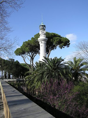
Billy and I were crossing the Tiber River's Garibaldi Bridge yesterday at sunset. Off to the West, with St. Peter's Basilica in view, we go a nice view of Venus under the crescent moon. Venus is now back as our "evening star." Also visible from the bridge is the "lighthouse" up on the Janiculum ridge. It's like a real light house, but it flashes the colors of the Italian flag. Very nice.

Wednesday, March 17, 2010

G.W. Pierce and the AA1TJ GiGi

Mike, AA1TJ, continues to provide the global solder-melting fraternity with large doses of QRP/homebrew inspiration. And, as usual, his latest series of messages to QRP-L contain interesting references to the radio pioneers who laid the ground work for his low power exploits. This time, it was G.W. Pierce.
-------------------------------------------------------
From AA1TJ on March 8, 2010:
Fellers,

It was an exciting QRPp afternoon here on 20m. It started off well
with a ten minute contact with G3MJX. Tony was running 5w to a dipole.
I'm still using the breadboard, two-tube, 250mW (Gigi) station that I
wrote about last week.

KB0PCI in Minneapolis was my next contact. Wayne was using 5w to an
indoor loop. I thought that was pretty cool.

Things seemed to be going so well that I felt the urge to further
reduce my output power. Dropping back to 56mW, I soon snagged Jack,
W7CNL. He's out in Boise with 5w and a five-element Yagi. It was a
great contact with 579/539 reports.

After we signed I resumed calling CQ. Sometime later I heard my call
coming back at me; always a happy moment when you're running QRPp. But
wait...he's signing DH1BBO...Holy Toledo!

With a pounding heart I sent off a 559 report. Olaf came back with a
529 for me, and get this...he says he's running 300mW to a windom! The
first round was an easy copy for both of us, but thing got a little
rougher after that. Still, we were able to hold it together through
the finals for a complete QSO.

Again, my transmitter circuitry is right out of 1928; a
crystal-controlled, push-pull oscillator using a single, 3A5 (a
twin-triode introduced by RCA in 1942). The receiver uses a second
3A5. The first triode forms a crystal-controlled autodyne converter.
The second stage is a standard regenerative detector driving the
headphones directly. My antenna is an end-fed wire at 35'.

Anyway, it was one of those QSO's that I dream about; QRPp on both
ends from start to finish, wire antennas at both stations and an
ultra-simple rig from the days of yore. It was Olaf's first QRPp DX
contact ever, and 57mW now stands as my lowest USA-to-Europe contact
power (230mW was my previous best).

As for working a 300mW German station with a receiver made from a
twin-triode; I think it's a testament to what these little
regenerative detectors are capable of. I was awestruck at the age of
12 or 13; having built my first genny. I love 'em no less some forty
years later as they truly are a beautiful technology.

73/72,
Mike, AA1TJ


From AA1TJ on March 3, 2010:
Bill,

Gigi worked AA7VW (running 5w to a Moxon) in Oregon today with 250mW.

I've been reading a bit of history here in preparation for my
presentation at MassCon next week. For example, I've traced the
crystal-controlled, push-pull transmitter (used in Gigi) as far back
as 1928. Cady and Pierce did their ground-breaking work on quartz
crystal-controlled oscillators in 1923, so it didn't take long for
hams to jump on this one. BTW, Professor George Washington Pierce
("G.W." to his friends) was a real character!

I send my best wishes to you and the family, Bill. The sap has just
started flowing here this week. It's Maple sugaring time in Vermont
again. Spring can't be far away now.

73/72,
Mike, AA1TJ

----------------------------------------------------------

Here is a bio on Pierce: http://profiles.incredible-people.com/george-washington-pierce/

This all makes me want to reconsider my opposition to regens... Maybe they are NOT possessed.

Sunday, March 14, 2010

Online Preview of SolderSmoke -- The Book, SALE!

I was working on the websites for SolderSmoke -- The Book, and I managed to set it us so that you can get a preview of the first part of the book. Just click on one of the links on the upper right hand side of this blog page, and look for the preview link (under the picture of the front cover). Lulu is running a 10% off sale this month. Use the coupon code "IDES" when you check out. (Very approriate - tomorrow marks the Ides of March.)
SolderSmoke Store on Lulu: http://stores.lulu.com/store.php?fAcctID=3999032

Saturday, March 13, 2010

Hamfest tips, 12 Volt Tubes and Cigar Box Radios

Bill,

Enjoyed very much listening to your adventures in the UK - I very much want to visit Faraday's lab!

When going to the next radio rally/hamfest, can I respectfully suggest the following:

A jacket or waistcoat with lots of pockets, the bigger the better. A backpack with some more bags inside. An idea also would be some kind of lock or restraint so that you could lock a full bag to a post or something out of the way in case you buy something heavy - I usually ask a stall-holder to look after a bag which they are often willing to do after I have made a reasonable purchase from them!

In one of the pockets put a small multimeter with a working ohms range - to test transformers, coils, valve heaters, etc. before purchase.

In another pocket put valve/transistor (or whatever you are interested in) data books or have a handheld thingy (iPhone, etc.) with a working Internet connection where you can look up such things.

In another pocket put a calculator (not needed if you have a handheld thingy) and a small notepad and pen/cil to make notes and work things out and compare prices from competing stalls.

A camera to take pictures of beautiful things you have no money for or intention of buying.

Some personal news:

Currently building a one-valve BC FM receiver - lots of fun. Recently built a MW 2-car-valve superhet which I listen to the World Service on here in Brussels. I build them into Cuban cigar boxes my missus gets free from tobacco shops around the city and in airports.

The fridge broke down and I discovered it was the thermostat and so I decided - foolishly - to spare the money for the replacement part (unemployed) and build one from components I already had in the radio room. Big mistake. I have been fiddling with different resistor values, broken Veroboard tracks and recalcitrant 740 op-amps for weeks now. Managed to freeze an entire bag of perfectly good carrots! I think I am on the tail-end of the prototype development process now and the production model should emerge in a week or so. The missus was initially impressed but now, sadly, not so. C'est la vie.

I experimented with QRSS using a simple PIC-controlled single car-valve crystal-regulated transmitter and a crystal immersed in a large jar of water for temperature stability. I managed to get seen by various grabbers and so am moderately happy. WSPR might be on the boards next, if I can do it with a PIC and a valve...

Good luck with the RC aeroplanes - try and keep the propellor pointed away!

73 cheers
Nick on4Nic / m0NjP

PS Car-valves are designed to operate from 12V only - heater and HT. Great fun for fiddling around with and completely safe - so long as you don't break them or burn yourself on the glass!


Friday, March 12, 2010

Cool Phobos Picture

This one is not from the recent fly-by. This one was taken by ESA's Mars Explorer in January 2007. I thought it was a very nice picture. There should be new close-ups of Phobos coming out this week.

Windows 2000, SMT, Olive Oil, Difference Engines

Hi Bill:

Just finished listening to SS 121. Fascinating as usual. In no
particular order:

- Microsoft is ending all support for Windows 2000 effective July
13th of this year. For us little guys there's only one impact, but
it's a doozy: no more security patches. My bench computer is still
Win 2k, so he'll either be losing his connection to the interwebs or
get replaced (don't think his little brain would take the current
Ubuntu release, but perhaps I'll give it a shot.) I'm a pretty tech
savvy guy so I've got no problem moving on, but I hate to toss
perfectly good hardware. Heck, I've got a 1965-vintage USAF surplus
VOM and a Fluke LED readout DVM on my bench (both relatively new to
me!) The scope, power supply and sig gen aren't much newer. I
think the odd duality of hams you pointed out (tech forward and also
sticks-in-the-mud) is another expression of an engineering mindset
that doesn't accept that the new must devalue the old.

http://blogs.technet.com/lifecycle/archive/2010/02/25/end-of-support-for-windows-2000-and-extended-support-phase-transition-for-windows-server-2003.aspx

- I'm starting to think the Sun has dropped life-cycle support for
HF, effective when I got my HF privileges. I'm following your weak
signal work with a lot of interest.

- I think I mentioned previously that I got to see the Babbage
Difference Engine #2 last fall. After hearing your Dobsonian
maintenance story using "API Grade Extra Virgin" olive oil, I thought
you'd be amused to hear that the BDE is lubricated entirely with corn
oil, which is apparently available in a variety of SAE weights. I
thought they should put a Bunsen burner under the drip pan and make
popcorn in there, but the docents weren't too impressed with my
engineering suggestions.

- SMT: I got my first serious taste of SMT while building, of all
things, a Nixie clock. It had two large quad flat pack (QFP) chips.
They weren't involved in the processing (which was done by a proper
DIP packaged PIC chip) but were the HV drivers (apparently actually
intended for use in a plasma TV). The manual instructed me to tack
down the corners, verify the alignment of all the unsoldered pins,
then just heat 'em and solder 'em down, ignoring pin-to-pin shorts.
After soldering all the pins, it then said to lay a piece of
desoldering braid on top of each run of pins, and heat it until the
excess solder wicked up. I was dubious, to say the least. But to my
complete surprise not only did the clock work on the first try
(meaning all 80 pins had been soldered correctly) but the chips
actually looked pretty good, too. Still a bit nerve wracking!

- In the "keeping old computers working" department I just ordered a
solid state drive to replace the oddball 1.8" drive in the little Dell
I use for travel. It runs Ubuntu pretty well, but I have to have Win
7 on there for work reasons, so I'm hoping the SSD will speed up the
latter (and not blow up the former - Linux and new technology haven't
worked out well for me in the past).

73,
Bob KD4EBM

Thursday, March 11, 2010

Faraday's Transformer Diagram

Looks familiar, doesn't it? Reminds me a lot of the toroidal transformer diagrams that you see in the Doug DeMaw books. This is from an 1831 lab notebook of Michael Faraday.

Wednesday, March 10, 2010

Faraday's Shack and the First Transformer

In London, Billy and I visited Faraday's workshop in the Royal Institution. Poor Michael set up shop in the servants' quarters in the basement. The shop is still down there (behind glass and well-preserved now). The painting above depicts Faraday at work in his shack.

On display was the very first electrical transformer. And guess what guys: It was a toroid! Here is a picture of it:

I found one of Faraday's drawings of the toroidal transformer and its windings. It looks a lot like the drawings of Doug DeMaw! I'll scan it and post it tomorrow. Off to work now.

Monday, March 8, 2010

Pop Sci! 137 years of Popular Science. Free. Online.

I know I promised more about Faraday today, but I think Michael would agree that this story should take precedence. Niels, PA1DSP, reports that ALL 137 YEARS of Popular Science issues have been made available FREE ON-LINE. This is Billy's favorite magazine. Amazing. We're all going to have to quit hour jobs to have more time for this kind of thing! Three cheers for the publisher and for the boys at Google for making this possible. Here it is:
http://www.popsci.com/archives
Designer: Douglas Bowman | Dimodifikasi oleh Abdul Munir Original Posting Rounders 3 Column