
Recently my trusty CCI EB63A .1kW amplifier has been in rebellion. On 10 meters, it now often insists on being an oscillator. It calms down nicely on 20 meters. But on 10, it has been a rebellious beast.
Why is this? Why would an amplifier that is well behaved and stable on 20 meters behave so badly on 10 meters?
I used LTSpice to explore the problem.
I looked at two ordinary wires. I gave them each a value of .003 uH. Very low. Then I joined them together in a transformer. I put a 1 volt signal into the primary and looked (in LTSpice) at how much of a signal appeared in the secondary. First, the result on 14 MHz. About 250 mV appears on the secondary.

Now consider what happens at 28 MHz. Nothing else in the circuit changes. Just the frequency.
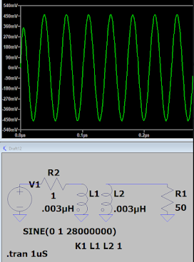
Here we get about 450 mV. A lot more.
Realize that my little EB63A amp has lots of wires in it, most of which are ready to serve as primary or secondaries in circuits like this. Increasing the frequency makes it more likely that a ginal will jump to someplace that it is not supposed to be. Output will couple to input and the Barkhausen criteria will be met. The amplifier will become an oscillator.
Of course, something similar happens with capacitive coupling. Same story: the higher the frequency, the harder it is to keep the amplifier stable.
Don't worry: Improved shielding is saving the day. The amplifier is now stable on 10. More about this in the next podcast...
good work om. try 1 GHz. can be murder!
ReplyDeleteI'm a very-fervent believer in *prophylactic* shielding, be it for RFI, EMI, feedback, or a few biological purposes. I don't know enough to know when it's really necessary.
ReplyDeleteBoth points from above commenters are true.
ReplyDelete1) More "fun" at 1GHz. And this 60GHz stuff I am doing is even more "funner"
2) "Prophylactic" is best term I have heard for this. Along with the other numerous sources of instability, shielding is one that the "cost-cutters" like to remove or "Muntz" so they can make their bottom-line look better. It does not cost as much as they think, and their savings never pan out. RF fields propagate!
I'm not so sure about the prophylactic shielding. You know, when we look inside the rigs of days-gone-by, we often don't see a lot of this. The Drake 2-B and the Halli HT-37 for example. Even in modern rigs like the BITX 40 module and the uBITX, the circuits are all just out there on the board. I have built rigs without any shielding at all, and they seem to work fine. Even the VFOs have no shielding (while many gurus claim that shielding of VFOs is absolutely necessary). The prophylaxis does add (significantly) to the complexity of a build -- this has to be considered a down side.
ReplyDeleteWell, prophylaxis *is* always awkward, and it's usually a cumbersome and fiddly disturbance in the drive to enjoy and finish . . . a project.
DeleteYea, same kind of problem!
DeleteAs your original post dealt with a Tx issue, we can just take the HT-37 example. Here is where strong RF fields exist on the same HT-37 chassis with a VFO operating at 5.0-5.5MHz. Their first good move is not operating the VFO at the Tx frequency. That's a plus especially for pulling. Second, the HT-37 designers were brilliant in the way they used the chassis itself, tube shields and fully shielded IF/RF transformers. The EMI shielding is there, especially on the component level. Currently, we have mostly unshielded components that can couple to each other as you found. The "component-level" shielding of the past is gone, except for items like toroids, etc.
ReplyDeleteTo keep costs in line, now we design the PCB's with provision for SMD shields ; provision costs us nil. And only if need be, these shields run <$1 at low qty.
It does take experience (and tact) to know where to make shielding provision at the design stage. Especially at Design Reviews! Lots of tact! Overall, its much, much less expensive than yet another board spin/ NRE, late penalties and engineer with "egg-on-the-face".
73!
WN2A
Well, I guess one of the benefits of being a radio AMATEUR is that egg-on-face does not lead to dismissal! Sure, some shielding is a no-brainer: I use shielded coax when carrying RF or even AF. I keep inputs far from outputs. I use a lot of by-passing on the DC lines. But I don't go as far as putting each stage in its own metal box with BNC inputs and outputs and decoupled DC inputs. Some people do. I think that might be overkill. Of course, I pay for this attitude (especially on 12 and 10 meters) when I find that the amplifiers are oscillating. Then I have to go back and find out where the Barkhausen criteria are being met. And I find myself wishing that I had used all those little metal boxes that I scornfully rejected! 73 Bill
DeleteI have been using some 5 and 10 mil brass sheet stock from ksmetals.com. Tin-snips, gloves recommended. Solders very nice. We have been using this to roll-our-own EMI shields. A you-tube video showed several ways of bending the sheet metal.
ReplyDelete