Just go to http://soldersmoke.com. On that archive page, just click on the blue hyperlinks and your audio player should play that episode.
http://soldersmoke.com
It is not every day that you get the chance to help a master homebrewer like Pete Juliano N6QW. But today is just such a day. Pete asks for some coding help:
For some reason we are more accustomed to impedance matching using tapped coils than we are with the use of tapped capacitors. This is too bad because tapped capacitors are a very useful impedance matching tool. Pete recently looked at this technique. Check it out:
I too have San Jian digital counters watching the stability of analog VFOs (DX-100, HQ-100, Mythbuster).
Variety is the spice of life!
I also liked Pete's comment about the fellow who does on-the-air menu counseling for FTDX-3000 owners. I sometimes run into guys on the air who want to do something similar with my simple homebrew rigs. They start by making comments about my audio -- they will usually say it is "too high" or something like that. Especially when I'm using the separate transmitter and receiver (which have to be "netted" imprecisely by ear), I have to explain that maybe resort to their RIT control would help. If they persist, I sometimes have to tell them that how my rig sounds depends A LOT on the placement of the carrier oscillator relative to the passband of the crystal filter (most recently, the filter from the 1963 Swan 240). Most of them have never had to do that kind of adjustment, so the "technical discussion" usually ends at that point, with my interlocutor saying 73, and presumably moving on to someone whose rig has menus to fiddle with. (Recently heard audio techno term: "massaging the codec.")
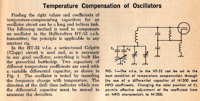
I've been watching with great interest Mike WU2D's excellent series on VFO construction. His second video is especially interesting because he talks about how we can use a split stator differential capacitor to build a temperature compensation circuit that will allow us to "dial in" the proper amount of temperature compensation.
The heart of this circuit is the split stator differential capacitor. The stator is split; but there is a common rotator. As the rotator moves, the capacity across one part of the capacitor increases while the other part decreases -- thus the total capacity remains unchanged. If we connect two capacitors of the same capacitance BUT OF OPPOSITE TEMPERATURE CHARACTERISTICS -- we can use this split stator cap to select just the right amount of temperature compensation. Very cool. Even cooler: Mike actually built a split stator differential capacitor. That, my friends, is dedication.
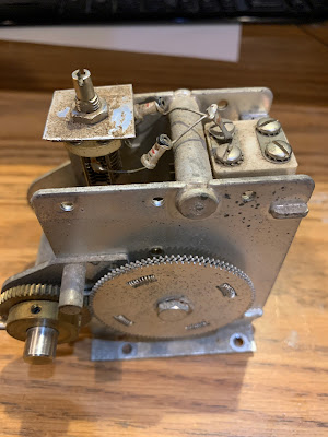
I was sitting here this morning thinking about all this when it occurred to me that right in front of me was a capacitor that might be relevant to all this (see above). I bought it on e-bay one year ago after Pete N6QW had alerted me to it. It is the main tuning capacitor from an HT-37 transmitter. What attracted us was the big anti-backlash mechanism. But now I realized that it had another charming feature.
Looking at it a bit more closely I saw a split stator differential cap just like the one that Mike had made. Attached to the two rotors were two tubular capacitors. The three caps are in parallel with the main tuning cap. Bingo -- this is a temp compensation circuit.
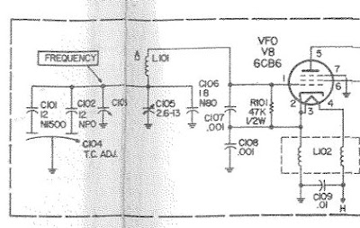
I checked the HT-37 manual. The manual says that temp compensation is set at the factory. OK. But the schematic does not show the split stator caps and the two tubular caps (see below). Could it have been that this circuit was added later perhaps to address drift? (We do see it in the HT-32B schematic -- see below.)
HT-37 VFO SCHEMATIC
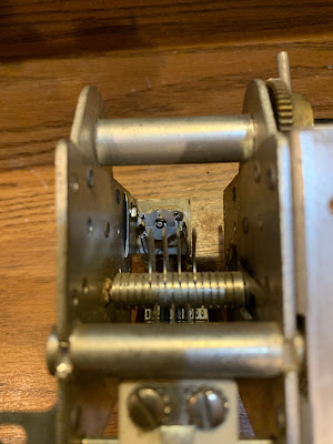
Anyway, it was very cool to find this example of the circuit Mike was discussing. In the photo at the beginning of this post you can see the three caps. Below you can see the split stator cap in the background.
In the comments a reader points out correctly that this circuit was discussed in the ARRL book "Single Sideband for the Radio Amateur." Indeed, it is on page 51 of the 1970 edition, ARRL gave credit for the circuit to Hallicrafters:
HT-32B VFO Circuit
Joe Carr K4IPV (SK) also discussed this circuit. In his article in Popular Electronics in August 1993, he too gave credit to Hallicrafters. Carr also gave some detailed instructions on how to use the circuit to stabilize a VFO. See pages 78 and 79 of the August 1993 Poptronics:
The Radio Gods seem to be pushing me towards Direct Conversion receivers. This week I was speaking via Zoom with the very FB L'Anse Creuse Amateur Radio Club in Michigan. My Herring Aid 5 tale of woe came up (see video above). Then Dean KK4DAS was sharing video of the amazing fidelity of the Pete Juliano Direct Conversion Receiver. Then I started thinking about Frank Jones W6AJF, and the story (fictional) of his build of the Herring Aid 5 by Michael Hopkins AB5L:
----------------------
I gave Frank a board for the Herring Aid Five redux from the April 1998 QRP Quarterly and challenged him to build one up. It took maybe two hours and that includes his own touches which included refusing to buy any parts.
For the transformers, he calculated the turns ratios from the impedances and tested a bunch of TV set pulls 'till he found something close. But he made the output 1:1 because his Brandes phones are close to 1000K Ohms as it is.
He was willing to use toroids, but not to buy one, so I gave him an Amidon circular and he calculated the values of the 18 specified units. Then he wound them on unidentified cores from my junk box after learning the permeability of each with his homebrew dip meter.
A store bought Zener was out of the question so he mixed and matched regular diodes with transistors hooked up as diodes until he got close enough to 10 volts. The mosfets came out of a TV tuner and Frank will use any plastic bipolar that says "C" or "D" on it for a 2N2222.
Of course it worked the first time. He rigged up a patch to a pair of Class A push-pull 6L6s so Christie could hear it and she said it was "Also cute but bigger than the other one."
Now a real QRPer would cry at that, but not Frank who sees no advantage in miniaturization at all. In fact, he mounted the whole thing in an old case from a Collins 6 and 2M transceiving attachment he junked out for the parts and no two knobs matched as Frank thinks matching knobs slow you down in a pileup. He wanted to take it back to his own shack and try it out with his breadboard MOPA and pair of 100THs because he does not run QRP, saying it "transfers the burden to the other guy."
-----------------
Frank Jones was one HARD CORE HOMEBREWER. No store-bought Zener diodes or toroidal cores for him!
All of the SolderSmoke Herring Aid 5 articles can be found here:
First, thanks to all who sent in suggestions. They came in literally from around the world, and this is a demonstration of the IBEW in action. I used or at least tried all of them. They were all good ideas.
Following Vasily Ivananeko's pseudonymous suggestion I rebuilt the carrier oscillator (apologies to G3YCC). I used the carrier oscillator/buffer circuit from Farhan's BITX20.
Henk PA0EME said I should look at the signal level at the input ports of the NE602 mixer. Henk was right --- the VXO input was far too high. I lowered it, but the problem persisted.
At first, I thought that the spur in question was so small that it would not show up on the air. I could not see it in the TX output using my TinySA spectrum analyzer. That was good news and bad news: Good that it was not showing up on the air, bad that I could not see it in the TinySA and use that image in the exorcism.
At first I thought that the spur was being caused by the 10th harmonic of the carrier oscillator and the third harmonic of the VXO. This seemed to fit. So, following VK3YE's sage advice, I built a little 69 MHz series LC trap (using a coil sent by AA1TJ, on a board CNC'd by Pete N6QW). That trap succeeded spectacularly in crushing the 10 harmonic. Look at these before and after shots on the TinySA:
Before Trap
After Trap
Spectacular right? But guess what? The problem was still there.
I scrutinized the situation once more. I realized that the spur would be more visible if I put the TinySA on the input of the transmitter's PA (a JBOT amp designed by Farhan) as opposed to putting it on the output. Watching the spur and the needed signal move in the TinySA as I tuned the VXO, I realized that they were moving in opposite directions. This indicated that the spur was the result of a carrier oscillator harmonic MINUS a VXO-generated frequency (as the VXO frequency increased, the spur frequency decreased). Looking at my EXCEL spread sheet, I could see it: 8th harmonic of the carrier oscillator MINUS the main output of the VXO.
To confirm this, I plugged the values into W7ZOI's Spurtune program. Yes, the spur popped up and moved as predicted.
For further confirmation I shut down the carrier oscillator by pulling the crystal from the socket, and then just clipped in a 5.176 MHz signal from my HP-8640B signal generator (thanks KB3SII and W2DAB). Boom! On the TinySA, the spur disappeared. Now I at least knew what the problem was: a harmonic from the carrier oscillator.
Following good troubleshooting practice, I turned off the gear and went to bed. When I woke up, an idea came to me: Before launching into a lot of filtering and shielding, just try running the carrier oscillator at a lower voltage, seeing if doing so might reduce the harmonic output. I disconnected the carrier oscillator board from the main supply and clipped in a variable voltage bench supply. Watching the signal on my TinySA, I watched as the spur completely disappeared as I reduced the voltage from around 13V to 10V (see video above). The main signal frequency level did not change much. I tested this by listening for the hated extra tones. They were gone. Exorcised.
Key lessons:
-- Spur problems are difficult to troubleshoot. Armstrong's superhet architecture is, of course, great, but this is definitely one of the pitfalls. Single conversion makes life easier. IF selection is very important. Choose wisely!
-- When looking at the TinySA as you tune the rig, pay attention to which way the spur is moving. This provides an important clue regarding the combination of harmonic you are dealing with.
-- The TinySA is a very useful tool. It seems like it is easier to use than the NanoVNA (which is also a fantastic tool).
-- It can be fun and rewarding to re-visit old projects. In the years between original construction and the re-look, new test gear has become available, and the skill and experience of the builder has improved. So problems that once seemed insurmountable become fix-able.
-- Thinking through a problem and thinking about possible solutions is very important. It pays to step away from the bench to think and rest. Rome wasn't built in a day. Here's a rough block diagram that I drew up (noodled!) while trying to figure out this problem:
The Lamakaan Amateur Radio Club's annual convention begins today in Hyderabad, India. This is Farhan's club so it is sure to be a great event. Presentations are being live streamed on YouTube and on the QO100 geostationary satellite.
Pete N6QW will be the first presenter and will talk about his new PSSST Rig. He will be speaking at 0430 UTC Saturday 11 December. That is 11:30 pm on Friday, December 10 on the East Coast of North America.
I will be speaking at 1130 UTC on Sunday December 12. That is 0630 Saturday 11 December EST. I'll be talking about the Mythbuster rig and about the ET-2.
I don't know how we might be able to watch or listen via the QO100 satellite. The U.S. is not in the footprint of this bird. But there is a good WEBSDR receiver run by BATC and AMSAT DL: https://eshail.batc.org.uk/
The other day I was complaining to Pete N6QW that 17 meters still seems to be in very poor shape. I can hear 6Y6Y around mid day, but I don't often hear Europeans. I did year my friend Mike EI0CL yesterday on 17, but conditions were not good. Pete asked, "Where is Cycle 25?" Good question. The Space Weather Center has the answer.
Their Solar Cycle Progression page is up-to-date. With the slider below each chart you can go back as far as 1750. Check out Cycle 19. I was born near the peak (TRGHS). Pete was on the air during that cycle. Cycle 23 also looked pretty good. I was out in the Azores then (2000-2003) -- no wonder I could work VK and ZL with a 5 watt DSB rig.
I like the little solar conditions widget that has appeared in the left hand column of this page, and I am grateful to the provider, but the widget just doesn't update regularly. So I think I'm going to switch to a link from the Space Weather Prediction Center that shows the numbers we really need: Solar Flux Index (SFI), Sunspot Number (SN), A index, K index. (Please let me know what you think about this change.)
Here is the link to the Solar Cycle Progression Charts (be sure to use the sliders):
It is especially appropriate for us to use that Irish phrase because the design of the rig's new final amplifier is out of Ireland. Our friend Dean KK4DAS added a 16 watt RF amplifier based on a design by EI9GQ to his homebrew N6QW Simple SSB rig. Note the IBEW label on the top.
Here is Dean's blog post on this wonderful project (with video and more pictures).
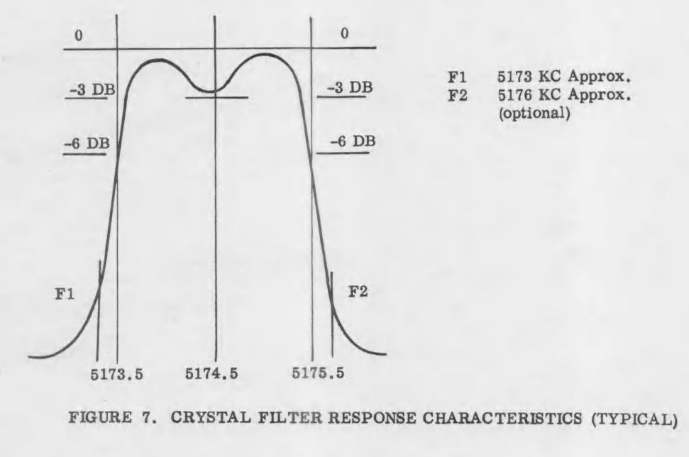
In SolderSmoke Podcast #234, I said that I was scrutinizing the filter from the Swan 240 that I had picked up around 1994 in the Dominican Republic. I cannibalized it out in the Azores in the early 2000s and used the parts to build -- among other things -- my first SSB transmitter. I never really focused much attention on the filter that I pulled out of that old rig -- I was just happy that it seemed to work. But I am now older and wiser, and I have some test gear that lets me look at the passband of that filter.
First, take a look at what it is supposed to look like. This is from the manual. Yikes! That passband looks far from flat. I can almost hear homebrewers around the world shrieking in horror and disgust.
Above is a description of the filter, and the schematic, again from the manual.
Here is what my extracted and somewhat re-built filter looked like in my NanoVNA (more shrieking!). The dip in the passband is a lot worse here -- it looks like 10 db vs. 3 db in the manual. This is probably because I'm not even attempting any impedance matching on the filter -- it is just seeing the 50 ohms in and out of the NanoVNA.
Here is my 2002 attempt to rebuild the filter and put it in my SSB transmitter, along with my more recent attempt to flatten the passband. I no longer had the adjustable coil L8, so I made my own coil based on guidance from Ben Vester W3TLN's January 1959 QST article on "Surplus-Crystal High-Frequency Filters." (Ben had an early influence on Pete Juliano's tube-rig designs.) In the picture above I have 1k pots between the filter and the input and the output of the NanoVNA, as described by Nick M0NTV.
Adjusting the 1 k pots, I could smooth out the passband quite a bit. Measuring the pots and adding the 50 ohms of the NanoVNA, it looks to me like this filter is smoother with about 280 ohms at the input and output. I may build two matching networks or some transformers. Some TIAs may also be needed.
Yesterday Pete Juliano published a blog post that contains an enormous amount of tribal knowledge and good advice for homebrewers. As I read Pete's post, I thought back on my own failed teenage efforts at homebrewing -- the Herring Aid Five fiasco came to mind. I also thought of Farhan's comments about his similar frustrations with early homebrewing efforts (though I find it hard to believe that Farhan EVER had trouble making something work).
Above we see a large N6QW prototype breadboard. Note how it is easy to see where the various stages start and stop. This is key to understanding and troubleshooting a complex rig. If you want to see the antithesis of this approach, here it is:
DO NOT BUILD IT LIKE THIS
This was supposed to be an 80 meter DSB transceiver. The builder (who will remain anonymous) obviously didn't get it to work. I think he should try again, using Pete's methodical approach.
The WFSRA: The World Friendship Society of Radio Amateurs.
Pete's Bench:
The Pimp. The NCX rig. The Collins. The many DC receivers built worldwide. The parts shortages are real! Several key radios on hold. Si5351 sub. Talk to G-QRP convention
Bill's Bench:
FT-8. Not for me. I tried it. Novice Station Rebuild. Globe V-10 VFO Deluxe. Selenium rectifier removal CONTROVERSY? Not crazy about my Novice station. Not crazy about CW. Mate for the Mighty Midget. Again. Mike W6MAB -- Detector problems LTSPICE Check One more mod for MMM RX. Ceramic filter at 455. Dropped screw inside tubular cap on Millen 61455 transformer. Talk to the Vienna Wireless Society Thinking of a Moxon or a Hex beam.
BOOK REVIEW Chuck Penson WA7ZZE New Heathkit Book. http://wa7zze.com
Mailbag
-- New SPRAT is out! Hooray! -- Todd K7TFC sent me copy of Shopcraft as Soulcraft. FB. -- Dean KK4DAS building an EI9GQ 16 W amp. FB. -- Jack NG2E Getting close on Pete's DC receiver. -- JF1OZL's website is BACK! -- Tony K3DY sent link to cool books. -- Sheldon VK2XZS thinking of building a phasing receiver. -- Peter VK2EMU has joined the WFSRA. FB! -- Ned KH7JJ from Honolulu spotted the Sideband Myth in the AWA video. -- Chris M0LGX looking at the ET-2, asks about the variometer. -- Pete Eaton Nov 64 anti HB rant in november 1964 QST. Wow. -- Josh Lambert Hurley spreading FMLA stickers in the UK. FB -- Stephen VE6STA getting ready to melt solder. -- Got a great picture of Rogier PA1ZZ back on Bonaire. -- Farhan reading the manual of Hans's new digital rig. -- Paul G0OER wonders if FMLA getting ready to move on 5 meters.
Wow, Scott got his Mate for the Mighty Midget receiver to work and he is obviously overjoyed with the result. All of us who have struggled with a homebrew project know just what this feels like. And it is very cool that Scott got some useful guidance from Charlie Morris in far-off New Zealand. Congratulations Scott. I'm really glad you stuck with it.
Scott's success comes at a good time: Pete N6QW is building W4IMP's three tube "IMP" SSB transmitter (also from the 1960s). I accept responsibility for naming Pete's project: It will be known as "Pete's IMP" or, memorably, "The PIMP." For a look at Pete's rig go here:
Scott had problems getting Lew McCoy's 455 kc crystal filter to work. So did I. It turns out that this is a very old problem, going back to World War II. In Don Stoner's 1959 "New Sideband Handbook" on page 54 he writes of homebrew filters in the 400 to 500 kc range:
"Inexpensive crystal filters constructed from war surplus FT-241 type low frequency crystals are very popular with the 'do it yourself' hams. These CT cut crystals have been plentiful and relatively cheap for a number of years and are in the hands of many Amateurs. The general run of war surplus crystals may or may not be good. Experience has shown that one out of four of these crystals are usually defective in one way or another."
Stoner was writing just 14 years after the war. Add another six decades to the age of these crystals -- often decades spent in musty basements -- and you can imagine the percentage of bad 455 kc FT-241 crystals increasing. So I think Scott is wise to seek an alternative to McCoy's crystal filter.
Scott's original build of the MMMRX receiver is just so nice. In the video he says he plans to go back to it after he gets the expanded version fully functional. He should definitely do that -- his original version looks so good. I think it is probably very close to working properly.
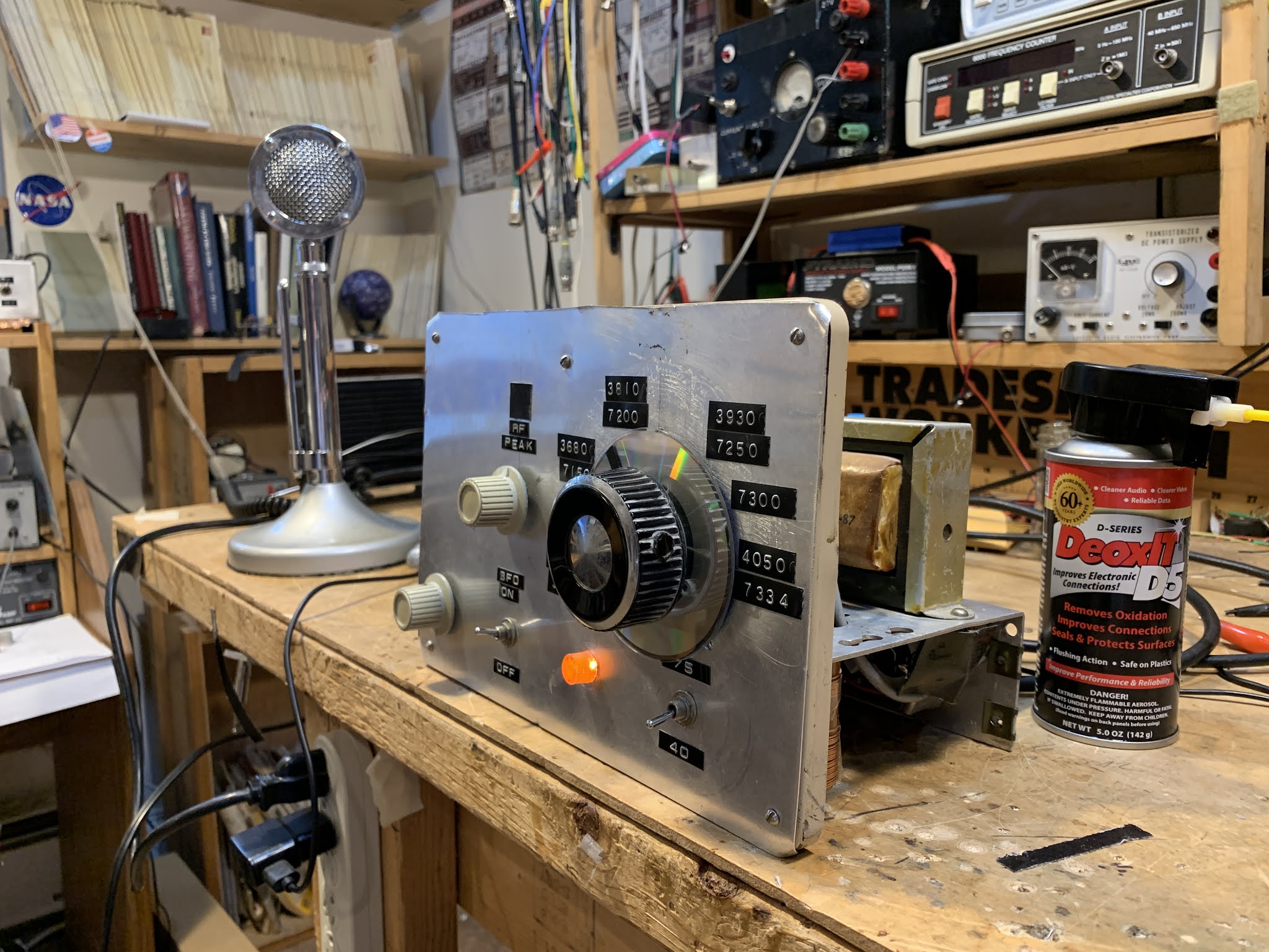
There it is. The 2021 re-creation of the WN2QHL Novice Amateur Radio Station. This is what I had when I first went on the air in April 1973 from Congers, NY.
-- I got my first Lafayette receiver (WITH JEWELED MOVEMENTS!) for Christmas in 1972. My mom drove all the way into New Jersey to get it for me.
-- I bought my first DX-40 and the Globe VFO Deluxe from someone in the Crystal Radio Club.
For this re-creation station:
-- I got this recently acquired Lafayette free-for-pickup from a very kind SWL in the Shenandoah valley. (I've discussed this receiver extensively here.)
-- The DX-40 is the result of a couple of junkers that I bought in a hamfest some 23 or 24 years ago. It might have been the Timonium Hamfest. I cannabalized one of them and made one good DX-40 out of the two. Parts of the cannabalized unit carry on the good fight as pieces of my balanced antenna tuner (the coils were useful there) and as the chassis for my first SSB transmitter.
-- The Globe VFO Deluxe was harder to recover. There are just not a lot of these things around. I actually put up a plea for one of these on the SolderSmoke blog. Not even the IBEW could come up with one of these things. But then, last week on Facebook I came across a fellow who was selling one. Deal! Check our the nice Juliano Blue light indicating 40 meter operation.
Putting these three devices together was more challenging than I thought. To get them to work together decently three different things had to happen as the result of throwing one switch:
1) Antenna had to switch from receiver to transmitter.
2) Receiver had to be largely muted (leaving some key-down signal for sidetone).
3) VFO had to be turned on (I left it running and just keyed the DX-40).
Fortunately I have almost 50 years more experience than I did when I first set this station up. So I was able to do this better in 2020 than I did in 1973. I had a 3PDT relay that I had built for a DX-60 station. I was able to use it to do all three things described above.
Muting the Lafayette was a bit tricky. On the back octal connector they have two post (1 and 3) that are normally connected. Disconnecting 1 from 3 completely mutes the receiver by cutting off a needed ground connection to the RF amplifier and to an IF amplifier. The Lafayette manual tells you to connect these terminals to the "muting voltage" presented by your transmitter. The DX-40 doesn't have such a voltage, and I was reluctant to connect any voltage to this terminal for fear of blowing up the RF and IF amplifiers. I figured that just putting a big resistor across 1 and 3 would mostly mute the receiver. The 3PDT relay shorts this resistor on receive, un-muting the receiver. I use a 500,000 ohm resistor. It works well, but the sidetone is chirpy while the actual signal is not. This is a bit annoying.
I re-capped the DX-40 when I got it back in the late 90's. Those caps are still good.
The Globe VFO had also been recapped. But it still has selenium rectifiers in there. I will change them ASAP. Also, the Globe VFO had a somewhat mysterious second transformer in there. I wondered what that was. I measured the output: 6.3 V. That is a filament transformer. My guess is that the filament winding in the main transformer went open, maybe as a tube failed. Instead of replacing the whole transformer, they just popped in a replacement filament transformer. That's fine.
I've been on the air with this rig, mostly on 40, as I was as a Novice. I can work anyone I hear on 40 meter CW and my CQ's are heard in Europe (as shown by the RBN).
I'm struck by how physically BIG these pieces of gear are. Much bigger than our beloved BITXs.
Regarding T/R switching: There was a line in the 1973 ARRL Radio Amateurs Handbook that really got to me back in 1973: Page 640, in the chapter entitled "Assembling A Station:" "
"In any amateur station worthy of the name, it should be necessary to throw no more than one switch to go from the 'receive' to the 'transmit' condition."
By this standard, my station was probably unworthy of the name. I don't remember how I handled T/R changeover, VFO keying, receiver muting and sidetone, but it almost certainly involved throwing more than one switch. But now, I am happy to report, my novice station is finally up to the ARRL's high standards. As Pete says, "When you know stuff you can do stuff."
It must have been great to have been a ham during the heyday of homebrew gear. Imagine walking into your local club and finding a dozen or so people who share your passion for melting solder and homebrewing your own equipment. Well, I got a taste of that thanks to the Vienna Wireless Society's Makers Group. Led by Dean KK4DAS, this group of intrepid radio amateurs has built versions of Pete Juliano's Simple SSB transceiver. They are finalizing the rigs; many are already finished. And I could tell from the questions and the discussion that I was talking to a bunch of guys who knew which end of the soldering iron to grab. It was really wonderful to talk to people who had gone through the experience of building an SSB transceiver, who knew from personal experience that it is not as easy as it seems. And I could tell from the questions that many of these guys are already thinking of their next projects, of how to put to use the experience they gained building Pete's SSB rig.
Dean asked me to talk to the group about my recently completed "Mythbuster" rig. This was a good topic for the group because my rig is similar enough to the Simple SSB that they could relate to it, but different enough that it could give them ideas about how they might do things differently next time.
I really enjoyed this session. I'm glad that VWS captured it on video. I think SolderSmoke listeners and readers will like watching this video.
Thanks to Dean KK4DAS and the VWS Makers group for hosting me. And thanks to Jacek KW4EP for helping with the video.
Here is the Vienna Wireless Society's YouTube Channel:
Idle hands are the devil's workshop my friends. I was home alone this week, and kind of ran out of things to do. I started thinking about all those signals on the FT-8 frequencies that I'd hear when the rest of the band was vacant. You know how it is: One thing leads to another. I remembered that Rogier PA1ZZ had sent me some interface boards. Soon I was downloading WSJTX. Then I bought a USB-Serial converter from Bezos.
I hit a major bump in the road when I managed to destroy the little optocoupler that the interface board used for T/R switching. No big deal though -- Pete has a simpler T/R circuit that worked fine:
I even made it a bit simpler -- instead of putting an SPDT relay on the Collector of the 2N3904, I just ran a lead to the PTT terminal on my BITX mic input connector. This terminal just takes one side of the BITX TR relay to ground on transmit. With Pete's circuit, the RTS signal from the computer causes the 2N3904 to conduct, in effect grounding the BITX T/R relay. Bob is your uncle. Building this little circuit was fun.
I used the 600-600 Ohm AF transformers on Rogier's interface board. I scrounged up the appropriate connectors and soon I was on 17 meter FT-8. After about an hour of casual operating (mouse clicking, really) I'd worked HC1HC, HI8CJG, DK4RL, J69DS, F5NBQ, PT2ADM, 8P6ET, KP4JRS, XE2YWH, F4DIA, EA4R, CO3DK, and HI3MRV. All this while no SSB signals were heard on the band. I was running about 50 watts to my 75 meter doublet tuned to 17.
The amount of DX you can work is impressive, but I don't know if I'll stick with this mode. It kind of reminds me of 2-way WSPR. I find myself wanting to TALK to the DX stations. FT-8 doesn't let you do that. But hey, I am not alone in trying out FT-8. In fact, one of the very first calls that I saw on my screen was the very familiar KB1GMX. That is Allison, a true radio genius. That's a good sign. So maybe I'll have to give FT-8 more of a chance.
"SolderSmoke -- Global Adventures in Wireless Electronics" is now available as an e-book for Amazon's Kindle.
Here's the site:
http://www.amazon.com/dp/B004V9FIVW
May 15,2024. Opportunities for Converted Radios
-
Could a Hackaday Lurker pull this off?
I have always had penchant for Ten Tec Radios and when I spotted a Ten Tec
Model 150A commercial radio an ide...
Stamp Commemorates 50th Anniversary of KBS
-
Many thanks to SWLing Post contributor, Paul Jamet, who writes: The French
department of KBS has sent me the postage stamp issued on October 19, 2023
to ma...
Moorabbin Radiofest
-
The Moorabbin RadioFest was a terrific show this year. The turnout looked
good to me although I'm told it was down on past years.It was great to see
a vend...
Broadcast Band AM Radio
-
See the YouTube series for more information:
http://www.youtube.com/c/CharlieMorrisZL2CTM
Buffer Amplifier
Low Pass Filter
IF Amplifier, Infini...
An Inline RF Step Attenuator for QRPp Work
-
I don’t need to explain the attraction of low power operation; if you’re
reading this, the chances are that you are already a convert. I’ve been
operating ...
A 51S-1 Restoration Story
-
I came across my Collins 51S-1 in a big junkyard in Ankara, Turkey around
2012. It was in a pile with a lot of other electronic scrap, probably from
one o...
New QRP Cluster Online From OM0ET and OM6APN
-
By DX EXPLORER
DX EXPLORER
Paul OM0ET and Peter OM6APN recently launched a new cluster dedicated to
QRP operations. Have a look and I hope you will enjoy...
3D Printing The Hadley 114mm Newtonian Telescope
-
Yes, we’re building a 3D Printed Newtonian Telescope called Hadley. It’s
being printed in PETG and in the video below, I give a quick tour. My build
isn’...
3D printed project boxes
-
I have been busy with some other things that have kept me away from
electronics projects for quite a while. Now I can get back to them, but
realize I n...
Daylight Again – An all Analog Radio
-
What’s all this? In 10 seconds, A high performance, 7MHz, 5 watt SSB rig
Draws just 24 mA of current 90 dB dynamic range, 80 dB close-in dynamic
range 3D ...
Adding Enclosure to your sBitx Boards Order
-
The early buyers of the sBitx board set who bought it for $270 USD might
want to also add the enclosure (box) for in the kit. What you will now get
is a f...
Digi-chirp! Digital synthesis of ‘nostalgic’ CW
-
The bottom ends of 80, 40 and 20m are not what they used to be. For
starters, the busiest part is the digital segment where computers talk to
computers – l...
-
A Simple Speech Processor
(For QRP/SSB Homebrew Transceivers )
Over the last few weeks I had been thinking to build a small AF speech
processor to add to...
A New Look for your uBitx!
-
Adding a "Cool Blue" Display to your uBitx!
The standard "green background" with black lettering frequently reminds me
that I suffer from Chronic seasickn...