A few days ago I received an e-mail from Jan PA3GSV -- Jan is working on a receiver similar to my old Mate for the Might Midget and had some questions about how I'd handled the filter portion of the circuit. Then on Sunday, while listening to Eric's interview with Farhan on the QSO Today podcast, I got so enthused that I felt compelled to work on a homebrew receiver. So out came the old Mate for the Mighty Midget. I built this thing in 1997-1998. It is described here:
In the above video I was listening on 75 meters to a very congenial early morning roundtable featuring W4CH, K5KBZ and others. I know, I know, this is the third or fourth video that I've made of this thing. This is almost as bad as 2B-mania. Or the Michigan Mighty Mite thing. I blame Jan. And Eric. And Farhan. And Grayson. And Lew McCoy!
Here is my e-mail exchange with Jan:
Bill:
I recently build the W1TS two tube xtal controlled transmitter, and am looking for a 80/40m companion for this that has a crystal filter.
At first, I wanted to build the “Simplex Super” and finally got hold of the 1700 kc crystals, but then they got lost in the mail…
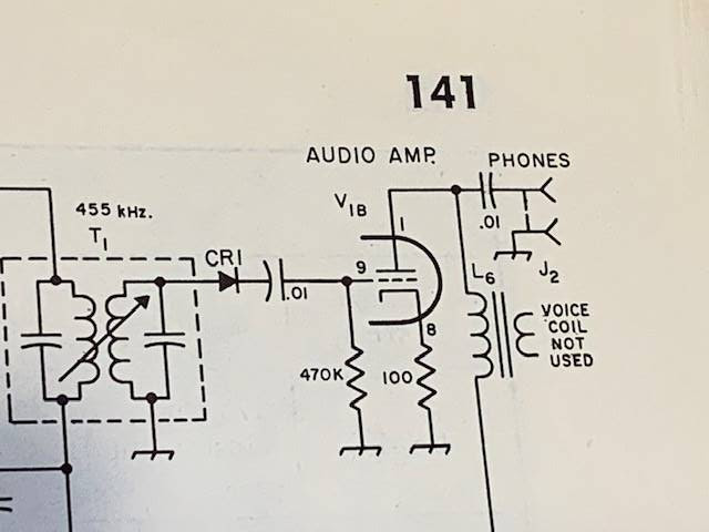
Only part of a two box shipment arrived, with 455 kc fundamental frequency FT-241 crystals, so now I am looking for a diagram using a 455 kc IF. Jan
Jan: In this link you will find the schematic for the receiver I built.
I was not able to build the filter with the two 455 kc crystals. I could not obtain the needed crystals. I used two 455 kc IF transformers as described in my article. This resulted in a very broad frequency response but it was OK and quite good for AM.
Last year I put in a Toyo 455 kc SSB filter, but I did not match the impedances, so the results were not good. Your e-mail makes me want to work on this again!
Let me know how your receiver turns out.
73 Bill N2CQR
Thanks for your reply.
It is a neat looking little receiver.
And yes, I also have a cardboard box labeled “good junk” which is filled with stuff from ham fests J
Finally it will be put to good use!
I printed the article for some evening reading this week.
It will take me some time building this receiver, as there is some metalwork and mechanics involved.
I will let you know how the receiver turns out, and I am also curious what improvements you make on yours.
Thanks again, and I will let you know.
73 Jan PA3GSV
Wow, Jan has the Knack! Check out his station:

That's the W1TS rig on the left. More pictures from Jan on his QRZ.com site. He too uses wood cabinets! I'm not alone! Here's Jan, PA3GSV