Podcasting since 2005! Listen to Latest SolderSmoke

Showing posts with label LtSpice. Show all posts

Saturday, March 3, 2012

CircuitLab Online Simulator


I gave the new CircuitLabs online circuit simulator a test drive this morning. It worked very well, even on my clunky old computer. I think this online system will open up circuit simulation for people who haven't used a simulator before. And it looks like a great tool for collaboration. Give it a spin!

https://www.circuitlab.com/

Our book: "SolderSmoke -- Global Adventures in Wireless Electronics"http://soldersmoke.com/book.htmOur coffee mugs, T-Shirts, bumper stickers: http://www.cafepress.com/SolderSmokeOur Book Store: http://astore.amazon.com/contracross-20

Wednesday, March 9, 2011

40 years of Spice

Bob, W8SX, sent me an interesting article from EDN on the recent commemoration of the 40th anniversary of our beloved SPICE program. Check it out:
http://www.edn.com/blog/IC_Design_Corner/40584-SPICE_a_40_year_old_open_source_success_story.php

Tuesday, January 11, 2011

ECHOLINK and WINE: Works very well

I've been away from Echolink ever since my eeemachines PC went toes up and wiped out the Windows XP operating system. Echolink had always been a bit difficult to get running, even under Windows, so when I returned the eeemachne to life with Ubuntu, I never really even considered trying to get Echolink running on it. There is no Linux version of Echolink. But then, yesterday, somehow I got inspired. Something told me I should give Echolink a try using the Linux WINE Windows emulator. After all, I'd found that LTSpice worked great under WINE. I went to the Echolink download site, and hit the button. Ubuntu Karmic Koala (the version I am using) automatically fired up WINE and put the new windows program in the appropriate place. Echolink started right up. That night I was able to check into the Sunday evening QRP group for the first time in years. It was great. Now I'm on Echolink in the morning, talking to hams in Western Australia. The cheers for Jonathan Taylor, creator of Echolink! And three cheers for Ubuntu (especially Karmic Koala)!

Monday, December 6, 2010

SolderSmoke 128 is out!

http://soldersmoke.com/soldersmoke128.mp3

3 December 2010
Visit to Wright Brother's Kitty Hawk site
Antenna work on Veterans' Day
W4HBK's Pensacola Snapper
"Knackers of the World Unite" (even in the UK!)
Sky and Telescope Jupiter moons program
Listen to a meteor ping!
DSB DC WSPR transceiver
Other ham books on Lulu
Ubuntu Karmic Koala's Skyrockets
Movie Review: "Social Network"
LTSpice under Wine (in Ubuntu)
Forrest Mims
Broken laptop -- need advice
MAILBAG
New puppy en route

I'll update the rss feed tomorrow.

Wednesday, May 12, 2010

Schematic for QRSS Transmitter

Here is the schematic for the little QRSS (visual) transmitter that is currently rockin' Europe's 30 meter band with an AWESOME 20 milliwatts of SLOOOW FSK. (As I type, it is 0415 UTC, 0615 local, and the first signs of my signal have just appeared on the ON5EX grabber up in Belgium.) The FSK modulation comes from Hans Summers' multivibrator circuit (see earlier posts).
It was a lot of fun to take this thing very quickly from LTSpice, to the workbench, then to the antenna, with Johan's grabber providing instant feedback. This started out as a one-stage Colpitts oscillator transmitter. But I needed more stability. Indeed, the separate oscillator with the source-follower buffer makes it much more stable. Before, any adjustment to the antenna tuner shifted the frequency. At one point I even suspected that wind blowing the antenna was shifting the frequency -- we are talking about a band that is 100 HERTZ wide, so even a few hz of instability is noticeable. But I find that crystal ovens and other extraordinary measures are not really necessary.

I had one unusual problem with this little rig: As I was doing my initial tests, I noticed that the output signal was sort of jumping up and down. The problem was in the PA. I isolated the problem to the base circuit. At first I thought that some small blob of solder was intermittently messing up the bias voltage (that's quite possible here in the N2CQR lab!). But no! It was that 4700 ohm resistor. It was bad, and kind of intermittently bad! I never had a resistor go south on me like this. It is an ordinary 1/4 resistor. It is not dissipating a lot of power.

I'll keep it around 10140010 today. Check it out on Johan's grabber:
http://www.on5ex.be/grabber/grabber.html
Look for a horizontal lines with little bumps (about 4-5 per minute). That's me.

Tuesday, June 2, 2009

Class C Amps and the Load and Power Out Formulas

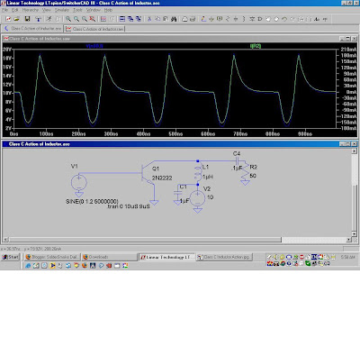
While up in Rotterdam I started thinking about Class C Amps and the standard formula used to calculate power out and load resistance: Rl=(Vcc-Ve)^2/2Po. I understand why this formula works for Class A amps: The Vcc-Ve term describes the maximum voltage you can get at the output. The rest of the formula is just a version of P=IE and P=E^2/R. The 2 in the denominator converts peak to average. The books tell us that this same formula applies to Class C amps. How could that be? I wondered. Doesn't the output of a Class C amp look (pre-filter) like a series of pulses at the operating freq? Wouldn't that require a somewhat different formula?
The answer came from SSDRA and LTSpice. SSDRA page 25 explains "If we assume that the collector voltage varies from zero to twice the Vcc level while delivering the desired output power, the load needed at the collector is given by the familiar relation Rl=Vcc^2/2Po." (Emphasis added.) The voltage at the collector is being pulled down nearly to zero as the voltage at the base goes positive and the transistor conducts. You can see this in the waveform in the LTSpice screenshot above. Then, when the input voltage dips below about .6 volts, the transistor goes into cutoff and stops conducting. At this point the energy stored in the inductor in collector circuit is dumped onto the collector, raising the voltage there to about twice Vcc. That the ugly spike you see at the top. Wow, you can really see from this the need for output filtering.
As I was exploring this issue, I cam across an old LTSpice VideoCast from December 2006. See below.
BTW: These are the kinds of questions explored in the book "SolderSmoke -- A Global Adventure in Radio Electronics." I'm hearing that delivery is very fast, especially in the UK.

Saturation and Class C Amplfier Efficiency

Originally posted on Gadgeteer News: 10 December 2006

FIRST LTSPICE VIDEOCAST

I made a 5 minute video using a video screen-capture program and the circuit simulator LTSpice. In addition to showing how LTSpice can
be used, the video looks at how saturation affects the efficiency of Class C amplifiers. I put the file on YouTube, but the video quality is poor when viewed through that service (it is difficult to see the graph lines in the YouTube version). So I have also uploaded the 26 meg file (.wmv)
to the http://www.gadgeteer.us web site.

Click here for the direct download of the .wmv file

Click here for the YouTube (lower quality) version

Saturday, March 28, 2009

Troubleshooting and Simulations

Alan, W2AEW, roams the Northeast USA as a Field Application Engineer for Tektronix. This week he sent me an e-mail with some words of wisdom about simulations and troubleshooting. Thanks Alan!

An excerpt from Alan's e-mail:

Funny you mentioned about LTSpice, and wanting to have that puff of soldersmoke whenever you place a component. It reminds me of something that I'd often tell new-hire engineers. Many times, engineers fresh out of school have never touched a resistor - they've often spent their entire education doing bookwork and simulations. I would always caution engineers about this, and try to illustrate that the simulation is only as good as the model you give it. If you ask the simulator to exercise the model in a way it wasn't designed for, it won't tell you that, it will just lie to you. YOU have to be smart enough to recognize the lie. For example, the simulator has no problem putting 10,000 amps through a 1N914A diode - it doesn't know that you'll let the smoke out of it! The simulator must be considered a tool, just as you VOM, scope, counter, finger, nose, etc. are all tools. Each can give you valuable information (and can lie to you). You have to learn to know what you can believe, and what you have to question - and you need to develop ways to look at strange behavior in a number of ways to figure out what is happening.

It reminds me of a story that Jim Williams wrote many years ago (you mentioned Jim Williams in a previous SS episode). He described how, as a child, he was playing with circuits at his neighbor's, and using his (neighbor's) oscilloscope to examine a circuit he was working on. He was getting all kinds of strange behavior, and couldn't make heads or tails of what he was seeing with the scope, VOM, etc. The neighbor (who was definitely afflicted with the Knack) came by and, with moistened fingers, probed around in his circuit for a few minutes. He then grabbed a small value capacitor and soldered it judiciously in the circuit, and everything worked fine. Jim was flabergasted and demanded an explanation. The neighbor said that he suspected that the circuit was oscillating at several hundred MHz, and used his finger's capacitance/loss/etc. to damp this behavior. He continued to explain that since the oscillation frequency was so high, the scope couldn't "see" it. Jim complained that this "wasn't fair"! The neighbor concluded the lesson about how important it is to not-only understand what our tools can do for us, but it is really more important to understand their limitations - because it is when we ask a tool to do something that it can't do, it often won't complain, it will lie. The same holds true for nearly every tool we use, and is a lesson well learned. This story is included in his chapter entitled "Should Ohm's Law Be Repealed?" in his book, "Analog Circuit Design: Art, Science and Personalities" from 1991.

Alan has a lot of great stuff on his web site. Check it out:
http://www.qsl.net/w2aew/

Saturday, February 21, 2009

W3JDR 's LTSpice NE602/SA612

Here's something we've needed for a long time: an LTSpice model for the ever-popular NE602/SA612 chip. Joe Rocci, W3JDR, developed this one back in December. You can download it, along with the LTSpice program (free!) from links on Joe's page:
http://w3jdr.ham-radio-op.net/ Thanks a lot Joe!

Speaking of Spice, Jim, AL7RV, has been e-cursing me for getting him involved with this highly addictive program. Jim has come up with an ingenious idea for making the simulation experience more realistic. I will tell you all about it in the next podcast.

Thursday, May 8, 2008

80 in the morning, LTSpice, QRP Blog

I am an early riser -- I am in the shack with coffee cup in hand each day by 0515. At sunspot minimum, that's just not the best time to be on the air. But 80 meters has come to my rescue. I've discovered that I'm not the only ham in Europe who gets up early. The CW guys are there first; phone ops seem to sleep in a bit. With my HW-8 and end-fed wire, I work a few stations each morning. (Today I worked TK7C on Corsica. ) Later on I listen to some AM enthusiasts who meet on 3705 kHz. And there is some great Italian tech talk (mostly about old tube rigs) on 3643 kHz. I plan on building an 80 meter DSB transceiver. (I've joked with Michael, AA1TJ, that on this project I plan to design first that THEN build.)

I've the LTSpice Yahoo Group for some guidance on how to model bifilar and trifilar toroidal transformers in LTSpice. I'm not sure I'm doing this right.

Found a great QRP Blog this morning: http://www.theqrper.blogspot.com/
Designer: Douglas Bowman | Dimodifikasi oleh Abdul Munir Original Posting Rounders 3 Column