Podcasting since 2005! Listen to Latest SolderSmoke

Showing posts with label Netherlands. Show all posts

Monday, August 29, 2016

Update on the PA3GSV M4MMRX -- And a Mystery


Note the establishment of a new acronym (M4MMRX) for Lew McCoy's Mate for the Mighty Midget receiver.  We  have needed this acronym for a long time, and SolderSmoke HQ is proud to have come up with it.  We do our part my friends.

Jan has made more progress on his amazing Dutch M4MMRX and has produced a short video showing the receiver in action with SSB and CW signals. 

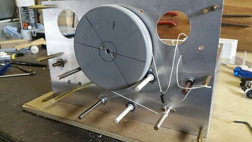
Here is a bit of intriguing homebrew mystery:  Jan has gone to a LOT of trouble to create that semi-circular opening in the center of the front panel.  He even cut a corresponding semi-circular hole in the sewer pipe cap that serves as the large wheel in his amazing homebrew reduction drive.  But he won't tell us what he plans to do with that space.  So I ask you, dear SolderSmoke readers:  What is that space for?  Why the see-through panel and sewer-pipe cap?  What is Jan's plan? 

From Jan:

Hi Bill,
 The rattle is gone, so I made a little video of the MMMRX in ssb and cw mode.

In the text, a ch327 and a ch45 crystal is mentioned, but I can’t get this to work.
The ch45 has a 453.6 kHz fundamental, for ch327 can’t find one.
The ch327 is a FT-243 one, tested several, but no fundamental somewhere around 455 kHz.
For ssb there is a ch45 and a ch46 crystal in, which should provide a bandwidth of about 2kHz.
(Still not totally in the clear how this should work with the very narrow resonance response of the crystals.
One should expect two peaks and nothing in the middle?)
For cw I found two ch45 crystals about 130 Hz difference in frequency, which seems to work well.

Still need to correct the 40m oscillator coil, then move on to finishing the receiver.
This is my first home brew tube superhet.
The project isn’t finished yet, but it sure is fun to build, and learned a lot during the process.

73  Jan

Sunday, August 21, 2016

First Signals from the PA3GSV Mighty Midget Mate


Obviously the Radio Gods (Spirits in the Sky) approve of Jan's work.  How could they not?  I can now see why he took the trouble to cut that hole in the sewer pipe cap that forms the large wheel on his homebrew reduction drive.  But what are we going to see through that center hole Jan?  What will the frequency readout be like?  
----------------------
Hi  Bill,

Just finished the last stage of the Mighty Midget MK2.
There are first signals!
The first one I heard was a broadcast station, believe it or not, the song that was on was “Spirit in the Sky” ..
All stages were built, tested and as far as possible, adjusted separately.
It was built from back to front, so the RF amplifier was last.
I added an ECL82 for more audio, the first thought of only using an EL84 didn’t bring enough.
The triode of the ECL82 as a pre-amp, the pentode as final.
Furthermore ECF82’s were used instead of the 6U8, they’re more widely available over here.
The Miller coils are hard to come by, so the 300 uH coils are homebrew.
Also used a grid detector instead of the two germanium diodes.
The triode of V1 originally intended for audio was used for this.
Made the BFO adjustable as well, still remember the screwdriver sticking out of the coil on your side... 
 
Happily there was not much troubleshooting needed.
The 80m coil was only 5 kHz off, the 40m coil 300 kHz (to low in frequency), still have to fix that.
Initially the receiver worked reasonably well without adjusting, but C1 quit at some point.
After some investigation, the problem was a dirty wiper contact on the rotor.
An ultrasonic bath fixed the problem, so no looking out for a replacement there. (hope it stays that way)
 
After adjusting, sensitivity is around -114dBm (0,4 uV) / 10 dB S/N!  (with the FT241 crystals in place, and careful tuning of the controls)
Really not bad for this small receiver, Lew McCoy was right, it really is a Mighty Midget.
I wanted to make some video’s, but over here there’s a terrible S9 rattle from 160 to 15 meters.
Every now and then it appears out of nowhere, and disappears the same way.
As soon as it is gone, I’ll make some video’s.
I made one video though, just after completing the receiver.
 
 
Reception on CW and SSB sounds really well, but unfortunately didn’t record that.
The receiver is not finished yet.
Next to the 40m coil,  S-meter has to be tried, and there’s still some work on the cabinet and front panel.
 
More to follow.
   
73  Jan
PA3GSV

Sunday, July 10, 2016

Update: PA3GSV's Amazing Mighty Midget Receiver (video)


Jan sent me an amazing update on his Mate for the Mighty Midget Mk 2 receiver project.  I'm really blown away by the skill that he brings to the mechanical phase of this project.   This is a homebrew dial-string reduction drive using the end cap from a sewer pipe as the big wheel.  Think about that.  Amazing. Jan reports that with the mechanical work almost done, he is almost ready to start melting solder.  FB Jan!  Check out the video above and the photos below.


Wednesday, June 15, 2016

Jan PA3GSV's Amazing Mate for the Mighty Midget

We have featured the amazing homebrew work of PA3GSV before:

Jan is at it again, this time building a Dutch version of Lew McCoy's Mate for the Mighty Midget.  Look at front panel! But wait, there is more!

Here is a side view of the chassis.  Wow.  What, you may ask, is that round thing?

Holy cow!  Homebrew Vernier reduction drive made from the cap of a sewer pipe.  And a homebrew dial cord arrangement.  Jan is clearly breaking new ground in ham radio homebrew re-purposing.

Jan writes:

Bill:
Here a little update on the MMrx.
Got almost all the parts, except for the Miller 4411 300 uH coils, for which I am attempting to make my own.
While I was looking for some pictures of this coil, if it was shielded or not (found a vintage online Miller catalogue J ),
I stumbled across this article, the W2MQ “Hamster”
There is no mention of the MMrx, but the text is very in line with the latter. Nice read.
 Also while looking for parts, I saw this supplier of FT-241 xtals who sell for reasonable prices ($10) .
Maybe you already know this company:
 Vernier drive 1:19
The drum is made from a sewerage end cap got from the hardware store.
Still under construction J
Added a front control to switch the BFO on/off, together with another crystal or some arrangement to make AM (broadcast) reception possible.
I want to try a regen detector instead of the 2 germanium diodes, followed by a pentode for some more audio output.
Regen and AF gain control are also at the front.
In your video it looked like there was a screwdriver sticking out of the BFO oscillator coil, a trigger to put this control on the front as well J
As there is no AGC, the (S) meter will measure the plate current of the RF amplifier tube.
So, a lot of experimenting to do, and still busy with some of the mechanics.
 73  Jan


Tuesday, April 5, 2016

My Mate for the Mighty Midget Thermatron Receiver


A few days ago I received an e-mail from Jan PA3GSV -- Jan is working on a receiver similar to my old Mate for the Might Midget and had some questions about how I'd handled the filter portion of the circuit.  Then on Sunday, while listening to Eric's interview with Farhan on the QSO Today podcast, I got so enthused that I felt compelled to work on a homebrew receiver.   So out came the old Mate for the Mighty Midget.  I built this thing in 1997-1998.  It is described here:

In the above  video  I was listening on 75 meters to a very congenial early morning roundtable featuring W4CH, K5KBZ and others.  I know, I know, this is the third or fourth video that I've made of this thing.   This is almost as bad as 2B-mania. Or the Michigan Mighty Mite thing.   I blame Jan.  And Eric.  And Farhan.  And Grayson.  And Lew McCoy!

Here is my e-mail exchange with Jan:

Bill:
I recently build the W1TS two tube xtal controlled transmitter, and am looking for a 80/40m companion for this that has a crystal filter.
At first, I wanted to build the “Simplex Super” and finally got hold of the 1700 kc crystals, but then they got lost in the mail…
Only part of a two box shipment arrived, with 455 kc fundamental frequency FT-241 crystals, so now I am looking for a diagram using a 455 kc IF. Jan

Jan:   In this link you will find the schematic for the receiver I built. 

 I was not able to build the filter with the two 455 kc crystals.  I could not obtain the needed crystals.  I used two 455 kc IF transformers as described in my article.   This resulted in a very broad frequency response but it was OK and quite good for AM. 
 Last year I put in a Toyo 455 kc SSB filter, but I did not match the impedances, so the results were not good.  Your e-mail makes me want to work on this again! 
 Let me know how your receiver turns out. 
 73  Bill  N2CQR

Thanks for your reply.
It is a neat looking little receiver.
And yes, I also have a cardboard box labeled “good junk” which is filled with stuff from ham fests J
Finally it will be put to good use!
I printed the article for some evening reading this week.
It will take me some time building this receiver, as there is some metalwork and mechanics involved.
I will let you know how the receiver turns out, and I am also curious what improvements you make on yours.
 Thanks again, and I will let you know.
 73  Jan PA3GSV

Wow, Jan has the Knack!   Check out his station:


That's the W1TS rig on the left.  More pictures from Jan on his QRZ.com site.  He too uses wood cabinets!  I'm not alone!  Here's Jan, PA3GSV


Saturday, February 27, 2016

Sputnik Replica Transmitter, an "Error" in the Sputnik Schematic, and Why 20.005 MHz?


Mark K6HX pointed me to very interesting Hackaday article on Frank PA3CNO's Sputnik transmitter replica.  As blog readers will recall, we went through a period of Sputnik-mania a few years ago:  http://soldersmoke.blogspot.com/search?q=sputnik  Chief Designer Comrade Mikhail Rainey AA1TJ sent me some of the Russian tubes (like those pictured above). 

The Hackaday article pointed to our post reporting that Oleg RV3GM had found the schematic:
http://soldersmoke.blogspot.com/2013/04/sputnik-schematic-found.html   Stefan reports that PA3CNO found "an error" in the original Soviet schematic:
http://www.radio.cc/post/Franks-power-supply-for-sputnik    A mistake you say?   HAH, I say!  Hah!  This must have been part of a sinister commie plot to prevent the capitalist imperialists from ever being able to reproduce the glorious transmitter of the Soviet people.  They almost succeeded. 

Just kidding.  

In the course of looking through our old Sputnik posts, I came across a question I posted:

I have a question: OK so the crafty Soviets picked 20.005 MHz for some good reasons: Being so close to the WWV freq, it would be easy for hams and SWLs to find it with precision. In the November/December 2007 issue of "Break In" (from NZ -- thanks Jonathan-san!) ZL3DW notes that this frequency selection would allow a receiver set to exactly 20 MHz to "produce an audio tone plus or minus the Doppler shift without ever going through zero beat." But zero beat with what? Most of the receivers out there would not have had BFOs, right? So the Soviets wouldn't have been using ordinary CW, right? Were they using AM, with the beeps produced by an audio oscillator modulating the carrier? 

Was their diabolical plan to use WWV as the BFO for those using ordinary AM SW receivers?   If so, a 5 kHz separation from WWV seems to be too much right?  Especially when the Doppler shift on approach would push the frequency up a bit. Maybe they just chose this freq to make it easy for listeners to find -- just a bit above WWV.  Comrade Rainey surmised that they were keying the PA stage -- the oscillator "backwave" was at times audible on the ground.

What do you think Comrades?
DSW and 73.

Tuesday, January 20, 2015

All of the Shortwave Spectrum LIVE on Web Waterfall Display


It's been a while since I checked in with this site.  They have made a lot of improvements.  It is very impressive.  I had trouble with it using Internet Explorer, but it worked right away using the Google Chrome browser.   Play with it a bit.  Zoom in on 40 meters.  Listen to the LSB contacts.  Very nice. 

http://websdr.ewi.utwente.nl:8901/


Our book: "SolderSmoke -- Global Adventures in Wireless Electronics" http://soldersmoke.com/book.htm Our coffee mugs, T-Shirts, bumper stickers: http://www.cafepress.com/SolderSmoke Our Book Store: http://astore.amazon.com/contracross-20

Wednesday, November 19, 2014

Electro-mechanical Heaven.... with Hell (Hellschreiber)


Bob LeDoux sent us a link to a really amazing site about the Hellschreiber system.  The site is filled with great videos, pictures, and animations like the one above.  Lots of radio history too.  Check it out: 

http://www.nonstopsystems.com/radio/hellschreiber-function-operation.htm 
This is all the work of F. Dorenberg, N4SPP.  Thanks OM! 

Bob writes:   I'm working on a microcontroller based reader for
this mode.  For old fossils, like us, this mode looks perfect.  It can
be sent using simple CW equipment and it appears to be a great
replacement for those who are tiring of Morse code.
Its perfect for Knack victims. We can even build mechanical printers. Thanks Bob!


Our book: "SolderSmoke -- Global Adventures in Wireless Electronics" http://soldersmoke.com/book.htm Our coffee mugs, T-Shirts, bumper stickers: http://www.cafepress.com/SolderSmoke Our Book Store: http://astore.amazon.com/contracross-20

Tuesday, September 23, 2014

A Beautiful BITX20 from PA1ED


Edwin did a beautiful job on his BITX.  This is an excellent example of stage-by-stage construction. 
This is his THIRD BITX.  On the second one he got all the parts from an old television and a washing machine.  That's the true BITX spirit!  
I want an S Meter!  
There is more information on his blog:
http://pa1ed.blogspot.nl/

Our book: "SolderSmoke -- Global Adventures in Wireless Electronics" http://soldersmoke.com/book.htm Our coffee mugs, T-Shirts, bumper stickers: http://www.cafepress.com/SolderSmoke Our Book Store: http://astore.amazon.com/contracross-20

Friday, June 7, 2013

Dutch Knack During WWII

 
de_jongens_van_de_hobby_club
 
There is a very nice article on the MAKE blog this morning: 
http://blog.makezine.com/2013/06/06/an-early-maker-story-from-holland/
 
Our book: "SolderSmoke -- Global Adventures in Wireless Electronics" http://soldersmoke.com/book.htm Our coffee mugs, T-Shirts, bumper stickers: http://www.cafepress.com/SolderSmoke Our Book Store: http://astore.amazon.com/contracross-20

Tuesday, January 29, 2013

Filter Pinout: P, E, B, G Explained


I few days ago I asked about the significance of the P, E, B, and G markings on my junkbox Toyo CM 455 kc filter (1969 vintage). PA3BCB -- in yet another example of the power of the International Brotherhood of Electronic Wizards --  was the first to provide the needed info.  And in another example of IBEW awesomeness,  KA0LDB noted that the markings are explained in the 1971 RSGB Handbook.   

P = Plate = filter input
B = B+     = mixer B+ plus if needed or input ground
G = Grid = filter output
E = Earth = Ground


I like the switched filter arrangement presented above (from the RSGB Handbook);  the 2.4 kc bandwidth is great for SSB, but a little tight for AM.  I might put in a DPDT switch in the circuit so as to be able to go back to the "broad as a barn door" selectivity provided by just the 455 kc IF cans.  


Our book: "SolderSmoke -- Global Adventures in Wireless Electronics" http://soldersmoke.com/book.htm Our coffee mugs, T-Shirts, bumper stickers: http://www.cafepress.com/SolderSmoke Our Book Store: http://astore.amazon.com/contracross-20
Designer: Douglas Bowman | Dimodifikasi oleh Abdul Munir Original Posting Rounders 3 Column