Just go to http://soldersmoke.com. On that archive page, just click on the blue hyperlinks and your audio player should play that episode.
http://soldersmoke.com
Farhan sent this picture yesterday. If you look closely you can see the students holding their homebrew 40 meter Direct Conversion receivers. You can even see that they are using the same kind of PTO coil forms that we are using here. Farhan reports that 11 receivers were built by 33 students. A few more are being finished and will soon be active in Hyderabad.
I was really blown away by this picture. We are doing the same things on different sides of the world. Our students will like this. It will be as if they are seeing people of the same age building the same receivers 7,500 miles away.
In our last session I mentioned to our students that Farhan of Hyderabad had given us the toroidal transformers that they are putting into their mixers. I told them that in ham radio, when we use parts given to us by a friend we add "soul to the new machine." And I said that Farhan would be coming to see them in May. They were really impressed.
We are starting to see similar efforts in different parts of the world -- Andreas with university students in Germany, Daniel with high school kids in Canada. We hope there will be others.
We've been giving out prizes for the first team to complete each stage. I wanted to give one of the teams a little oscillator that could b heard with their receiver. So this morning, using a 7040 crystal from the AF4K (SK) company, I threw together a one transistor oscillator. It has just 8 parts, including the key:
I had a low pass filter in the antenna tuner. The antenna was a low-to-the-ground 40 meter dipole. The transmitter was putting out around 100 milliwatts.
N2CQR's Ten Minute Transmitter
The Reverse Beacon Network showed that I was getting out quite well:
Then I thought, wait a second, let's make a contact with the prototype high-school direct conversion receiver.
With the receiver hooked up, I again called CQ on 40 CW. BOOM! Very quickly Alan W4AMV in Raleigh NC came back to my call. Wow! That's 222 miles. And a quick check of QRZ.com revealed that Alan is a homebrewer. Then Google reminded me that his work has been featured on the SolderSmoke blog. TRGHS.
I was so excited during this contact that I almost forgot to film it. But I did manage to get some short clips of the QSO in progress. You have to listen carefully, but you can hear our calls in there while Alan is transmitting (listen for the lower tone):
UPDATE (Feb 27 2023): I asked Alan about the rig he was using: "A PLL EXCITER DRIVING A PAIR OF FETS PUSH PULL ABT 50 w to an inverted L at 55 feet. The Rx a single conversion 9 MHz IF and it is connected to an active antenna in the trees out in the woods abt 25 feet up. Uses an automotive whip antenna about 3 feet long. "
Alan's Rig
This little contact is a reminder of the fun that can come from using simple, homebrew, QRP gear. It is really amazing that the very first contact with this receiver was with another homebrew station. This all reminds Dean and me of something we have been telling the students: the little DC receiver they are building is not a toy -- it is capable of being used in real, long-distance contacts.
A team from the Vienna Wireless Society was back in the local high school Thursday and Friday of this week, helping the students finish their variable frequency oscillators and build their diode ring mixers. Club President Dean KK4DAS was in the lead, and did an amazing job working with the school and procuring all the needed parts. Mike KD4MM and Don KM4UDX provided patient and understanding help to the students.
Students at work on the receiver
On the oscillators, the students had to add about six parts to install a buffer circuit built around a J310 FET. They also had to replace some of the 3D printed coil forms for the main-tuning variable inductor. (Dean KK4DAS made some really nice forms -- see below.) Several teams of students experiences were very pleased to get their oscillators running.
Manhattan Mixer Pads
Then it was on to the diode ring mixer. We had planned on having the students wind their own trifilar toroids, but we realized that this might be too much -- it would add a lot of time to the build, and would introduce a lot opportunity for error.
One of Farhan's transformers
I remembered that Farhan had given me a big supply of FT-37-43 trifilar toroids that had been assembled in Hyderabad. We decided to use these transformers. We reasoned that this was not a big deviation from our DIY ethos -- after all, we didn't ask the student to wind their audio transformers, nor did they wind the RF choke in the VFO buffer. But we faced a problem: the Hyderabad transformers were all wound with the same color wire on all three turns. This would make it hard for the students to figure out which wire went where (there were 12 such wires on each mixer board!). I figured out how to do this: The night before, I soldered together the center tap wires, and I twisted together the input coil wires. We told the students to first solder the center taps in place, then solder the two free wires to the diode ring, and finally untwist the input coil wires, soldering in these connections. This worked.
How the transformers were prepped
Before we started, I gave the students a quick class on the essentials of mixers. And I pointed out that we were using transformers made in Hyderabad India and donated by our friend Farhan. I told the students that whenever we include parts given to us by a ham radio friend we are adding "soul to the new machine." Indeed, Farhan's toroids added a lot of soul.
We have been insisting that the students have each stage tested before moving on to the next. This week we used signal generators to put RF and VFO energy into the mixers, and oscilloscopes to make sure that audio was coming out.
One of the test set-ups for the mixers
The students are making good progress. After today's session we did an estimate of where each of the projects stand at this point:
We are building 15 receivers. Oscillation without the buffer: 11 Oscillation with the buffer: 5 Mixer built and tested (but no diplexer yet): 5 Mixer working, diplexer built 2
During the next month or so the students will build the bandpass filter and the audio amplifier, and put all the boards together to complete the receiver.
Thank God for the Wayback machine. For a moment I feared that this article about Farhan's DC-40 receiver had been lost. (Phonestack is now some Vietnamese vendor. ) But the WayBack Machine archive came through for us.
I really like Farhan's blow-by-blow description of the build. There are raw emotions here: He speaks of his hatred of LM-386s, and of how he thought of using the copper clad board as a projectile. His niece wonders about the possibility of evil spirits in the receiver. The battle against AM breakthrough is very familiar. (I like the RF choke idea.) You won't find candor like this in QST or QEX.
Farhan's DC-40 project was one of the inspirations for our high school effort. In fact, when we first went to the school, I left behind a direct conversion receiver that I had built. Taped onto the bottom of the receiver was a quote from the DC-40 article and a picture of the Wizard of Hyderabad. (See above, and click on the picture for a better look).
This week we will inject some more Farhan-ismo into our receiver. The time has come to build the mixer. Like Farhan, we will go with the diode ring. Winding the transformers would be very time consuming. I remembered that on his visit, Farhan had left me a box of trifilar toroids wound by the seamstresses of Hyderabad using FT37-43 cores. We will uses these in our build. They will add a lot of soul to the new machine.
Dean KK4DAS and I were at the high school on Thursday and Friday of this week for the construction (by the students) of the variable frequency oscillator stage of their analog, discrete, direct-conversion receivers for 40 meters. Most of the students have already obtained their Technician Class licenses, so they are already radio amateurs. Both the licensing classes and the receiver build are being done with the assistance of the Vienna Wireless Society.
A week earlier Dean and I had demonstrated how to build the oscillator stage using the Manhattan technique (isolation pads super-glued to copper clad boards), but this week was the first time these students were actually building anything like this themselves.
We deliberately did not "spoon feed" the students. We told them that while we would be on-hand to help, THEY would have to do the building. They would have to layout the pads on the PC board, select the parts (from a table set up by Dean), and do the gluing and soldering. We did not hand the students bags of parts, or prepared PC boards. This was not going to be a kit building session. We wanted this to be real homebrewing.
We had parts for 15 receivers. But on the first day there were more than 60 students. So four students per project. On the first day we actually ran out of soldering stations.
We cautioned the students against dawdling. We told them to get on with it, and to "make haste slowly." We also injected an element of competition into the build by announcing that the first team to achieve oscillation would win. (Prize still TBD).
By the end of the Thursday session, many boards had been built but there were not yet any oscillations. We reconvened on Friday afternoon -- Dean and I set up support/troubleshooting stations.
Right off the bat, one of the students came up with a board that he wanted to test. After one quick correction (enamel still on the oscillator coil leads), my frequency counter showed that it was oscillating. I fired up my DX-390 receiver and we heard the loud tone. We had a winner!
In the following hour or so, Dean and I did troubleshooting on about 10 more boards. We found some of the problems that we would all expect (because we have all made these mistakes ourselves!):
-- There were cold soldering joints. We showed the students how to properly solder -- usually they just had to re-heat some cold-looking connections.
-- A few of the Zener diodes and transistors were wired in backwards (been there, done that).
-- A few of the feedback capacitors were of the wrong values. Dean and I had brought some good caps, so the students were able to quickly swap out the parts. This was another good lesson.
-- There were a few wiring errors -- these were quickly corrected.
It was exciting. One-by-one we would hear the whoop-whoop as the DX-390 confirmed that another oscillator was OSCILLATING! The students really liked to HEAR the oscillations that they had created. We reminded them at the beginning that they would be taking DC from a little square 9 volt battery and turning it into RF that could (if connected to an antenna) be heard around the world, or in our case be used to receive signals from around the world.
We got eight of the oscillators going. We think the students will be able -- without much help from us -- to get the remaining seven oscillators going.
They learned a lot. They learned about the ease, flexibility, and usefulness of the Manhattan technique, and we think they could see how this represents a basic kind of PC board design. Their soldering skills improved a lot. And they learned how to troubleshoot: Is the layout correct? Are any parts wired in backwards. Is the soldering OK? Are any of the parts bad (or of incorrect values)? Most importantly, they learned that they CAN build circuits themselves, and actually get them working.
The real payoff came each time oscillation was achieved. The students were really amazed and pleased. I could tell that some of them weren't really sure their little device was actually creating the signal they were hearing. So while we listened to the DX-390, I asked them to disconnect and reconnect the battery. Confirmed. Oscillation! Smiles. It was really great.
Soon, after finishing up some PTO odds and ends, we will move on to the other stages. We'll probably do the bandpass filter or the mixer next. Then the AF amp. Then put it all together into a full receiver. We think each stage will get easier and easier to build as the students learn and improve their homebrewing skills and their self-confidence.
We've often reminded the students that what they are doing is NOT easy. This is hard. As new radio amateurs, they are taking on a project that most older hams never dare to take on. They like the challenge. They are homebrewing a real receiver.
It is truly a thing of beauty. Stephen VK2BLQ built it just as we designed it, so his build (like those of several others) serves as confirmation that this design is ready for the high school students.
Stephen writes:
Bill,
Don't worry, you are not alone out there.
Here is my build; sorry that the front panel is overexposed and hard to see, but it is plywood.
I did follow the schematic but due to the contents of the junk box there have been some component changes.
The only thing that I had to buy was the 3/16 x 50 mm (2 inch) brass screw.
My calculations for the coils for the PTO and BPF were a little bit off necessitating padding down the PTO with a further 100 pF (easier than remaking the coil and mounting) and removing a few turns from the T50-6 toroids.
Like other people have found: the audio takes off at full volume; I am thinking but not yet tried adding decoupling between R5 (15K) and C2(47 uF). It isn't the actual values of the electros as I had to use 100 uF so might be the audio output getting back into the earlier stage.
The tuning range I get is our 7000 to 7200 KHz and some shortwave stations above and below, Turning the screw is a little bit fiddly, but once tuned the vfo is quite stable and the audio sounds good.
Best wishes,
Stephen
VK2BLQ
I really like the ruler near the tuning control. Is that (I hope!) the frequency readout?
Rick N3FJZ has completed his the direct conversion receiver that we will soon be building with students at a local high school. See video above.
We are hoping that a number of people will build the receiver as we designed it. Some folks have sent us versions of the receiver that they have built, but these versions often include significant deviations from our design, rendering them less-than-useful in checking our work. Rick built it just as we prescribed. His build is very useful in confirming the validity of our design. So if you are working on one of these receivers, I would encourage you to -- for the moment -- dispense with innovations and build it the way Rick did: as per the design we have been using.
We know that our design is not perfect. But we have decided to stick with it because it is very simple and very easy to explain. Examples: We know there is an impedance mismatch between the mixer and the AF amp. But fixing this would introduce complexity that we want to avoid. And the receiver works fine with the imperfection. We know that a push-pull AF amp would probably work better than the one we have. But we do not want to have to explain push-pull amps, biasing schemes, and PNP transistors in this short introductory course. So we stuck with three common-emitter AF amp circuits and an 1K-8ohm transformer.
Rick did a really excellent job not only in building this receiver, but also in documenting it. His diagrams and drawings are really superb. We will probably use these in our presentations to the students:
We will keep all of you informed on the progress of this project. We will begin this week. But if you are still working on the receiver, please send us your work, even if it comes in after we begin the course.
I superglued a San Jian frequency counter to the front panel of my High School Direct Conversion receiver. Then I tuned it through the 40 meter band. You can hear the W1AW/4 station. And several SSB stations.
Wonderful progress from Rick N3FJZ. Having completed the PTO, Rick went on to build the diode ring mixer and diplexer. (See video above.) He then connected these to boards to a band pass filter and an AF amp from previous project. And wow, the resulting receiver sounds really great! I think it sounds better than the ones Dean and I have built.
-- It will be interesting to see how Rick's receiver sounds with the very simple AF amplifier that we are using.
-- We need to get Rick a coil form for the PTO variable inductor! And getting him the PTO form will allow him to dispense with the varactor circuit (which, I must say, is pretty cool).
-- In the PTO, for the coupling capacitor (C15) , I now have a 260 pF NP0 cap. But your .1 uF ceramic disc seems to be doing just fin. So maybe we don't need the NP0.
-- I'm glad that Rick grounded the brass screw. Without that, the hand capacitance effect is bad.
-- I think results will be much the same with the dual tuned circuit bandpass filter that we use. But it will be interesting to see if Rick's triple tuned circuit helps with AM breakthrough (I think I heard Radio Marti when Rick tuned to the top of the band).
-- I haven't had a hum problem and I don't think Dean has either. Dean is running his on two 9V batteries. Maybe that would take care of the hum. Our PTOs are completely Al Fresco!
When I saw this, I found myself thinking two things:
1) Those really are "rigs."
and
2) I am not alone!
Years ago, I was having a tough day on 40 meters. The Waterfall Policemen were gleefully attacking my admitedly less-than-perfect SSB signal. Unbeknownst to me, someone out there was listening, and listening with a homebrew receiver. A receiver with a PTO. It was Rick N3FJZ. He made my day when he sent this video:
So far, in response to my recent request for testing, no one has stepped up to build the DC receiver Dean KK4DAS and I are testing out. We did get a couple of comments explaining why guys are opting not to help, but so far no other builders are actually melting solder in response to our recent request.
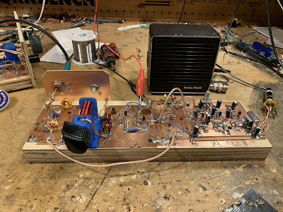
So Dean and I decided to each build second versions of the receiver. That will bring the total finished build population to 4. I finished my second version yesterday. Picture above. It works great.
One change: The emitter resistor on the final AF amp was too low in value. The transistor and the transformer were getting hot. I switched from 10 ohms to 100 ohms and the problem disappeared. I have made the change on the LTSpice Schematic. Here is the .asc file (I hope!) :
You will notice that this Spice schematic actually works! The PTO turns on, and I put a simulated RF signal at the antenna port. Audio appears at the output.
Time is getting very tight. Dean and I will begin presenting this project to the high school students on February 2. So it is not too late to help. But helping is, of course, strictly voluntary -- if you are reluctant to build this thing, DON'T!
This is the Direct Conversion receiver that Dean and I have built. We plan to have students at a local high school build it, starting in early February. We would like to have some others build it, to make sure that the design is re-producible without problems.
Please build this receiver! But we ask that you build it exactly as per the schematic above and below. Innovation can come later -- for now we just want to make sure this thing works, that there are no errors in the schematic, and that it can be built by the students with minimum woe. Thanks in advance!
Dean or others with 3D printers may be able to supply the plastic form for the PTO inductor.
We know of one other builder, but he is having some trouble. We would like to confirm that this design is sound.
-------------------
Above is the screenshot of the LTSpice model of the 40 meter Direct Conversion receiver that Dean KK4DAS and I have been working on. I will post a larger scale version of the picture below. Click on the images for a better view. Comments welcome. Please let us know if you find any errors or mistakes. Realize that we wanted to keep this all simple, discrete, and entirely analog.
Here (I hope!) is the net list for the LTSpice model:
First, one of the surprising things about the LTSpice model: IT IS ALIVE! I never had a VFO or PTO actually turn on for me in LTSpice. This one did! So I just connected the PTO to the Mixer and the receiver works in LTSpice. I just put an RF signal at the receiver input, and you can see the resulting AF across the 8 ohm resistor at the audio amp output. I was even able to calculate the precise frequency of the PTO: 7078 kHz. As in the real world, in an effort to stabilize the frequency, I changed the capacitors to NP0 in LTSpice. Very cool. Dean joked that all we need is a way to get RF in and audio out and we will have made an SDR receiver.
About the receiver:
-- Four stages that will be built by students Manhattan-style on four copper clad boards: Bandpass filter, diode ring mixer, Permeability Tuned Oscillator (PTO), AF Amplifier.
-- The bandpass filter is a simple dual-tuned circuit device based on the info on the QRP Labs site. (Thanks Hans!) We out a 10k pot as an RF gain control between the antenna and the filter.
-- The mixer is a standard diode ring. We included a diplexer at the output using a circuit from the famous W7EL Optimized transceiver. (Thanks Roy!)
-- The Permeability Tuned Oscillator is a very simple and very stable Colpitts design developed by Farhan VU2ESE. We added a simple FET buffer using the circuit in Farhan's Daylight Again rig. (Thanks Farhan!)
-- The AF amp is a very simple three transistor amplifier based loosely on designs from Forrest Mims and from the Herring Aid 5 receiver. Both these designs use just two stages -- we added a third and put an AF gain pot between the first and the second stages. There is an impedance mismatch between the diode ring and the AF amp, but we found that most of the proposed solutions were more trouble than they were worth, so we left it as is.
--Thanks to Wes W7ZOI for his November 1968 QST article on the solid-state DC receiver. Wes's article inspired our efforts.
Dean and I have both built these receivers. They work very well. Dean has even decoded FT-8 with his. We used Radio Marti at 7355 kHz to test for AM breakthrough -- with the diode ring, the diplexer, and the RF gain control we were able to bring the AM breakthrough down to acceptable levels. You can see many videos of my receiver in action over on my YouTube channel: (355) SolderSmoke - YouTube
Here is a larger image of the schematic (click for a full view):
And here is a nicer schematic done by our friend Walter KA4KXX:
Walter KA4KXX in Orlando has been a prolific builder of rigs for many years, and has been a great friend of SolderSmoke: Here are some of the SolderSmoke podcasts and blog posts in which Walter's solder melting was mentioned: https://soldersmoke.blogspot.com/search?q=KA4KXX
As we approach the end of our current stay in the Dominican Republic, I could not miss out on the chance to work Walter with his homebrew rigs. Even though the space weather was stormy, and my dipole was droopy, we arranged to meet up on the high end of the 20 meter CW band this morning. See the results in the video above. A solid QSO with Walter. He says it is HB2HB, but truth be told I was on a uBITX that was built more by Farhan than by me. But this was a great contact. Walter started with a 50W rig, then switched to his 3 watt rig with a DC receiver. FB
Here is the e-mail I received from Walter after the QSO:
Dear Bill:
Many thanks for the great video, and when
you return to Virginia look for your mailman
to bring a postcard from me!
Just after your phone call this morning I scanned
the band from 14.025 to 14.300 and heard only one
SSB QSO at 14.347, and even now I only hear
a half dozen SSB signals, so that makes what
we did even more amazing.
The first photo below is my 3.5 watt NE602 direct conversion
rig which is about 2 years old. The transmit signal is created
by putting a 3 MHz VFO signal into an NE602 mixer with an
11 MHz crystal, so the rig can receive CW and SSB from
14.025 to 14.300 and can transmit CW anywhere in that range
with good frequency stability.
The bottom photo is my new full break-in CW 50W rig which
I just put on the air about a week ago and is still in the finalization stage.
I am not yet happy with it, but then again I am more particular
now than I used to be. It is really a trans-receiver with a single
conversion superhet receiver at the bottom of the board using
an NE602 pair with a 3-crystal 4 MHz 900 Hz bandwidth filter,
and a single 10.080 crystal VFO which is tuned with a polyvaricon
for operating between 14.061 and 14.068 MHz.
At the top is the VXO transmit section using a pair of 14.070
crystals pulled down into the operating range. This signal
is buffered and amplified to about 500 mW which is all that
the MRF101 RF Power Amplifier needs. Visible behind the
board is an AC-powered 24 VDC switching power supply which
is connected in series with the 12 VDC battery to
power the final stage with about 36 VDC. The main 12 VDC is
provided by a bench power supply which is not in the photo.
In both rigs the morse code key is the microswitch
at the lower right corner. (Way more handy and elegant
than your key, I might say?)
This morning each of these rigs was connected to its own
end fed half wave antenna, one in my backyard
and the other on the side of my house. My antenna analyzer
shows them to be essentially equal, but my 50W rig does
not like one of them at all.
Making our international homebrew-to-homebrew contact
today was a terrific ham radio experience, so thanks for all
When "direct conversion" receivers came along in 1968 (the concept existed before, just not the name), it was to build simple receivers. They took over from regens (which of course for the purpose of CW and SSB, were "direct conversion"), and kind of bumped simple superheterodyne receivers out of the magazines.
And they were easy to build, so long as the meaning of the dots were standard, but good performance was elusive. Endless articles about better mixers or more front end selectivity, and still the same basic results The Heathkit HW-7 comes along, and endless mods to that, but still no perfection.
Slowly the move was back to simple superhets, especially with some of the early seventies ICs intended for radio, and then ladder filters came along (actually they came early at least by 1974 from the UK and/or France, but while they got mention in North America early-ish, it took some years before the KVG filters were pushed aside and ladder filters got the spotlight).
And then wham, in the mid-eighties someone caught on. The problem with direct conversion receivers wasn't the mixer (well not once it was a balanced mixer) or lack of front-end selectivity, it was the matter of properly terminating the mixer. The problems that had been there all along were gone. And direct conversion receivers started their climb to being complicated receivers.
I guess it was that receiver by Gary Breed in QST circa 1986 with diode balanced mixers and termination that changed things. A new concept, but not really, I remember an article in QST in 1974 where a DBM diode mixer for VHF was properly terminated, and yet the concept went no further until a decade later.
Actually, I think there is a tiny bit about mixer termination in "Solid State Design for the Radio Amateur" but it never went so far as to say "this is what we need".
Or perhaps that tiny transceiver by Roy Llewellyn in QST was the first, I cant' remember. It certainly used a diode mixer with termination for the receiver.
And that set the stage for Rick Campbell's various receivers, all counting on termination of the mixer.
The ideas can often be there, but not applied because technology doesn't allow it yet, or just not looking that far beyond this month's construction article.
I've said this before: I just seems so unfair. We just should be able to listen to DSB signals with our beautifully simple homebrew Direct Conversion receivers. I mean, building a DSB transmitter is a natural follow-on to DC receiver construction. And we are using AM shortwave broadcast stations (Radio Marti --I'm looking at you) to test our DC receivers for AM breakthrough. But when we tune these stations in, they sound, well, awful. So unfair! Why? Unfortunately it has to do with laws. Laws of physics and mathematics. Blame Fourier, not me.
Over the years there has been a lot of handwaving about this problem. From Doug DeMaw, for example:
In his "W1FB's Design Notebook," Doug wrote (p 171): "It is important to be aware that two DSSC (DSB) transmitters and two DC receivers in a single communication channel are unsatisfactory. Either one is suitable, however, when used with a station that is equipped for SSB transmissions or reception. The lack of compatibility between two DSSC (DSB) transmitters and two DC receivers results from the transmitter producing both USB and LSB energy while the DC receiver responds to or copies both sidebands at the same time."
That's correct, but for me, that explanation didn't really explain the situation. I mean we listen to AM signals all the time. They produce two sidebands, and our receivers respond to both sidebands, and the results are entirely satisfactory, right? Why can't we do this with our Direct Conversion receivers? I struggled with this question before: https://soldersmoke.blogspot.com/2015/07/peter-parker-reviews-dsb-kit-and.html You can see in that post that I was not quite sure I had the answer completely correct.
It took some discussion with a fellow Vienna Wireless Society member, and some Googling and Noodling for me to figure it out. But I think I've got it:
Imagine a station transmitting a DSB signal at 7100 kHz with a 1 kHz tone at the AF input. There will be signals at 7101 kHz and at 7099 kHz. Assume the carrier is completely suppressed.
We come along with our DC RX and try to tune in the signal.
Remember that they heart of the DC RX is a product detector, a mixer with the VFO (or PTO) running as close as we can get it to the suppressed carrier frequency (which we can't hear).
Lets assume that we can somehow get our VFO or PTO exactly on 7100 kHz. The incoming signals will mix with the VFO/PTO signal. We are looking for audio, so we will focus on the difference results and ignore the sum results of the mixing.
The difference between 7101 and 7000 is 1 kHz. Great! And the difference between 7099 and 7000 is 1 kHz also. Great again, right? We are getting the desired 1 kHz signal out of our product detector, right? So what's the problem?
Here it is: SIDEBAND INVERSION. Factoring in this part of the problem helps us see the cause of the distortion that plagues DSB-DC communication more clearly.
Remember the Hallas Rule: Whenever you subtract the modulated signal FROM the unmodulated signal, the sidebands invert. So, in this case, we are subtracting that 7099 "lower sideband" signal FROM the 7100 VFO/PTO signal. So it will invert. It will become an upper sideband signal at 1 kHz. We will have two identical 1 kHz signals at the output. Perfect right? Not so fast. Not so PERFECT really.
The perfect outcome described above assumes that our VFO/PTO signal is EXACTLY on 7100 kHz. And exactly in phase with the suppressed carrier of the transmitter. But if it is even SLIGHTLY off, you will end up with two different output frequencies, signals that will move in and out of alignment, causing a wobbling kind of rapid fade-in, fade-out distortion. You can HEAR this happening in this video by Peter Parker VK3YE, starting at 6:28:
And you can see it in this LTSpice simulation.
This LTSpice model just shows two diode ring mixers. The transmitter is on the top, the receiver is on the bottom. The transmitter has RF at 7100 kHz at L1 and audio at 1 kHz at R1. The receiver has the VFO at 7100.001 L7, DSB from the transmitter at L12 with audio appearing at R4. It is instructive to watch the output as you move the VFO frequency. If you move the VFO freq away from the transmit carrier osc frequency you will see the distortion. Here is the netlist for the LTSpice simulation:
On paper, using simple mixer arithmetic, you can tell that it will be there. With the VFO/PTO just 1 Hz (that's ONE cycle per second) off, you will end up with outputs at 1.001 kHz and at .999 kHz. Yuck. That won't sound good. These two different frequencies will be moving in and out of alignment -- you will hear them kind of thumping against each other. And that is with a mere deviation of 1 Hz in the VFO/PTO frequency! We are scornful when the SDR guys claim to be able to detect us being "40 Hz off." And before you start wondering if it would be possible to get EXACTLY on frequency and in phase, take a look at the frequency readout on my PTO.
Now consider what would happen if the incoming signal were SSB, lets say just a tone at 7101 kHz. We'd put our VFO at around 7100 kHz and we'd hear the signal just fine. If we were off a bit we'd hear it a bit higher or lower in tone but there would be no second audio frequency coming in to cause distortion. You can hear this in the VK3YE video: When Peter switches to SINGLE Sideband receiver, the DSB signals sound fine. Because he is receiving only one of the sidebands.
The same thing happens when we try to tune in an AM station using a Direct Conversion receiver: Radio Marti sounds awful on my DC RX, but SSB stations sound great.
My Drake 2-B allows another opportunity to explore the problem. I can set the bandwidth at 3.6 kHz on the 2-B, and set the passband so that I will be getting BOTH the upper and the lower sidebands of an AM signal. With the Product Detector and the BFO on, even with the carrier at zero beat AM sounds terrible. It sounds distorted. But -- with the Product Detector and BFO still on -- if I set the 2-B's passband to only allow ONE of the sidebands through, I can zero beat the carrier by ear, and the audio sounds fine.
There are solutions to this problem: If you REALLY want to listen to DSB with a DC receiver, build yourself a synchronous detector that gets the your receivers VFO EXACTLY on frequency and in phase with the transmitter's oscillator. But the synchronizing circuitry will be far more complex than the rest of the DC receiver.
For AM, you could just use a different kind of detector. That will be the subject of an upcoming blog post.
Please let me know if you think I've gotten any of this wrong. I'm not an expert -- I'm just a ham trying to understand the circuitry.
"SolderSmoke -- Global Adventures in Wireless Electronics" is now available as an e-book for Amazon's Kindle.
Here's the site:
http://www.amazon.com/dp/B004V9FIVW
WHAT TO DO WITH 3CX3000F1
-
A number of years back, I was at the Sussex Hamfest, and a 3cx3000f1 jumped
out at me and said 'Take me home'.
I had an idea of building an induction heate...
Wireless sound mixing
-
I don't go out to see bands very much but recently we attended a dinner and
show by The Martini Set. It was an enjoyable evening but what caught my eye
was...
April 27, 2024. Tubes or Transistors?
-
A recent acquaintance and newfound friend suggested I cover the tube versus
transistor dilemma. Some Blog readers may even be saying why are you
wasting my...
Power standing wave null… solution
-
Power standing wave null… more left readers with “homework” to create the
Pfwd and Prev traces. Remember that Pfwd and Prev are interpretations in
the cont...
An Inline RF Step Attenuator for QRPp Work
-
I don’t need to explain the attraction of low power operation; if you’re
reading this, the chances are that you are already a convert. I’ve been
operating ...
Using an external clock with the RX-888 (Mk2)
-
*The RX-888 (Mk2) and external clocking*
*Figure 1:*
The RX-888 with external clock input *(right)*
The enable/disable switch is barely
visible behind the...
A 51S-1 Restoration Story
-
I came across my Collins 51S-1 in a big junkyard in Ankara, Turkey around
2012. It was in a pile with a lot of other electronic scrap, probably from
one o...
New QRP Cluster Online From OM0ET and OM6APN
-
By DX EXPLORER
DX EXPLORER
Paul OM0ET and Peter OM6APN recently launched a new cluster dedicated to
QRP operations. Have a look and I hope you will enjoy...
3D Printing The Hadley 114mm Newtonian Telescope
-
Yes, we’re building a 3D Printed Newtonian Telescope called Hadley. It’s
being printed in PETG and in the video below, I give a quick tour. My build
isn’...
3D printed project boxes
-
I have been busy with some other things that have kept me away from
electronics projects for quite a while. Now I can get back to them, but
realize I n...
Daylight Again – An all Analog Radio
-
What’s all this? In 10 seconds, A high performance, 7MHz, 5 watt SSB rig
Draws just 24 mA of current 90 dB dynamic range, 80 dB close-in dynamic
range 3D ...
Adding Enclosure to your sBitx Boards Order
-
The early buyers of the sBitx board set who bought it for $270 USD might
want to also add the enclosure (box) for in the kit. What you will now get
is a f...
Digi-chirp! Digital synthesis of ‘nostalgic’ CW
-
The bottom ends of 80, 40 and 20m are not what they used to be. For
starters, the busiest part is the digital segment where computers talk to
computers – l...
-
A Simple Speech Processor
(For QRP/SSB Homebrew Transceivers )
Over the last few weeks I had been thinking to build a small AF speech
processor to add to...
A New Look for your uBitx!
-
Adding a "Cool Blue" Display to your uBitx!
The standard "green background" with black lettering frequently reminds me
that I suffer from Chronic seasickn...