Podcasting since 2005! Listen to Latest SolderSmoke

Showing posts with label test gear. Show all posts

Thursday, September 10, 2020

The Agony of Troubleshooting -- From China


I am troubleshooting my beloved NYC HP8640B Signal Generator (thanks to Steve Silverman and Dave Bamford).  Some of you may wonder why I don't just replace this beast with something small, lighter, cheaper and newer.  Well, I have not found any new sig generators that will do what this beast does:   It goes all the way up to 256 MHz (higher with an extension kit).  It has a great attenuator in it so you can set the output just where you want it.  AM or FM modulation.  Really useful.  So I think I'll fix it. 

My problem is that the internal freq counter stops working above 16 MHz. Using the very extensive  documentation, and without even really opening up the machine, I think I have located the fault.  I think it is in the Counter Time Base Assembly board A8A3.   Now of course, the fun begins.  (Tips, advice, solutions, and words of encouragement would all be appreciated.) 

While planning my assault on A8A3, I came across the web site of BH1RBG.  He too has recently been working on an HP8640B.  His problem was different, but when I read through his site I saw evidence that the agony of troubleshooting is something that is the same all around the world.  Check out his description of the agony: 

I even suspected the LM723 should had something bootstrapping circuit, make sure the Q4 sure start. Because the external reference VR3 is floating too, oh, my godness.

I became hopeless, and ordered several LM732,and waiting delivery for days. This beast frustrate me so deeply, changed the LM723 does not help anything. And i almost desoldering everything in the board!

Oh man, I've been there. Several times while in the throes of a troubleshooting battle I have actually had dreams of removing all the parts from a troublesome PC board.

BH1RBG has a very interesting site with lots of ham radio projects: 

https://sites.google.com/site/linuxdigitallab/rf-ham-radio?authuser=0


Sunday, September 6, 2020

Marc Verdiell Has The Knack


Here is Marc Verdiell, the "Curious Marc" who repaired the Soyuz Clock (shown in yesterday's blog post).  

Really cool.  Many SolderSmoke fans will completely understand Marc and his passion for 
electronics. 

Saturday, September 5, 2020

Taming Glitches in a Soyuz Space Clock (Plus -- Inside a Logic Chip and How Crystals Work)


Thanks to Bob KD4EBM for sending this.  

There is so much good info in this video:  They crack open a logic chip and look at the internal construction (it is entirely understandable by mortal minds).  They use cool test gear to troubleshoot the clock from a Soyuz spacecraft.  They explain very clearly the series and parallel resonances of quartz crystals, then display these resonances on a very nice spectrum analyzer.

The creator of the video is CuriousMarc.  He has many other interesting projects: 

https://www.youtube.com/c/CuriousMarc/featured

https://www.curiousmarc.com/ 

His bio is here: 

One paragraph from his bio really resonated with me: 

Working on this old stuff forces me to deal with the very fundamentals of electronics (and electro-mechanics). The principles are exactly the same as today, but nothing is hidden in mysterious circuits - you can understand and fix everything. Years of Moore's law has sure given us gobs of transistors, oceans of memory and a glut of gigacycles, but many times, particularly in consumer hardware, these are simply used to cover up poor and inefficient designs - and resource devouring software. What Intel giveth, Microsoft taketh away, as they say. It often irritates me that my PC takes several seconds to react to a simple command, in which time it must have executed billions of unnecessary instructions and consumed a few gigabytes of memory, no one knowing exactly what for anymore. Nothing like this in old high-end hardware: designs are pure and efficient, and the lack of resources is compensated by engineering mastery and immense cleverness, which is a joy to reverse engineer. Not only does it teach us timeless electrical fundamentals and engineering tricks, but it also gives us a much better appreciation of today's tech. How did all the technology we take for granted came to be? It will make you a far better engineer and inventor if you take the time to be a thorough student of the inventions of your illustrious predecessors.

Friday, August 28, 2020

Andreas Spiess (The Guy with Swiss Accent) -- Workshop Tips


Thanks to Paul Taylor VK3HN for alerting me to the YouTube channel of Andreas Spiess.  There are lots of great projects there, including several videos on building an Oscar 100 ground station.  

In the video above, Andreas talks about his lab/workshop.  He is more focused on digital projects than I am, but I found many of his tips applicable to the analog world. And of course the more digitally oriented readers will find Andreas's observations especially useful. 

I was sold on this video when Andreas reached to his book shelf and showed us Tracey Kidder's "Soul of the New Machine."   That is the book that brought the word "soul" into the SolderSmoke lexicon. 

There are many great videos on Andreas's channel.  I found his Playlists page to be a good way to see the many different catergories of his projects: 

https://www.youtube.com/c/AndreasSpiess/playlists

Thanks Andreas. 

Sunday, August 23, 2020

Mike WU2D's Great Drake TR-3 Refurb Video -- Part 2


Mike WU2D made another very nice video about his Drake TR-3 refurb. 

He cracked me up when he noticed that one of the calibration oscillators was 30 Hz off.  "Let's pretend we care," said Mike.  Indeed. But it was probably wise to tackle this problem, given how upset modern hams seem to get with 30 Hz discrepancies.  Mike noted that the problem was casued by "aging cystals." Yikes! Another thing to worry about, along with the Southern Magnetic Anomaly. 

Once again Mike has added a useful term to our lexicon:   "The Dribble Method" of signal injection (or extraction):  Just wrap a few turns of insulated wire around the tube or IF can and inject or measure away.

Neutralization! Now there's a blast from the Thermatron past.  I haven't done that in a long time. I liked Mike's "reverse neutralization" method. 

Mike's video featured some real Boatanchor eye candy.   That Heathkit HR-10 receiver caught my eye, as did that HP signal generator. 

Thanks Mike.  One hand behind your back OM.    

Saturday, August 1, 2020

SolderSmoke Podcast #224: Mars. Spurs. Bikes. SDR. NanoVNA. Antuino. MAILBAG


SolderSmoke Podcast #224 is available:


1 August 2020

--The launch of Perseverance Mars probe with Ingenuity helicopter.
--China’s Tian Wen 1 on its way – radio amateur Daniel Estevez EA4GPZ is listening to it! 
--Sci Fi Books:  Mars Trilogy by Kim Stanley Robinson.  No skip on Mars :-(
--We have some sunspots!  SFI now 72 and the Sunspot number is 23. 

Bill's bench: 
--Conquering Ceramic Spurs in Q-31   Roofing filter -- sort of 
--NE602 for a Q-75 converter – Gilbert Cell. 
--Measuring low power levels out of NE602.  Antuino better than 'scope . 
--NanoVNA   Really cool stuff.  SDR in there. 
--Building a 455 kc LC filter from QF-1 rubble. Using LTSPICE, Elsie... 
--Reviving my bicycle AM radio – The “All Japanese 6”
--Understanding L Network impedance matching. 
--Bill’s new resistor kit from Mouser. Thanks to Drew N7DA. 

SHAMELESS COMMERCE:  PATREON, AMAZON SEARCH.  THANKS

Pete's Bench: 
--Lockdown Special 
--BPF work on SDR Rig
--I U W I H 

Mailbag:
VK3HN Summit Prowler 7
VK2EMU “The Stranger”
SM0P  HB uBITX in Dubai
AE7KI  Worked him in VK from London
ON6UU  EA3GCY’s 4020 rig
KA4KXX A Simpler Mighty Mite
W9KKQ M19 DMR
KD4PBJ Radio Schenectady
W3BBO 12AU7 Regen
KE5HPY Another 12AU7 regen
N5VZH Ne602 Converter
KY3R Wall Art
G4WIF  Spectrum Analyzer in your pocket
W2AEW  Talks to UK Club
KK0S Sent 455 Kc IF cans
KL0S Making 9Mhz filters
VU2ESE  Diving into simple SDR schemes
Dean KK4DAS  Amateur Radio Astronomy

Sunday, July 26, 2020

Alan Wolke W2AEW on IMD, NanoVNA and more (presentation to UK club)


This video is another reminder of how lucky we are to have Alan Wolke W2AEW as a fellow radio amateur, and as a teacher and mentor. 

In this video, Alan is talking to the Denby Dale Amateur Radio Society in Yorkshire, UK. 

The first part of his talk is about IMD products, the importance of 3rd order products, and the benefits of attenuation. 

The second part of the talk (after a few questions) is a look at the NanoVNA, which Alan cites as the "Toy or Tool of the Year."   

I learned a lot from both portions of the presentation.  I now find myself wanting an H4 model of the NanoVNA (bigger screen).  Or maybe even an F model.   Thanks to Alan, I now know what S21 and S11 means. 

Thank you Alan, and thanks to the Denby Dale ARS.  

73  Bill 
  

Wednesday, July 15, 2020

An Attenuator from Fred KC5RT


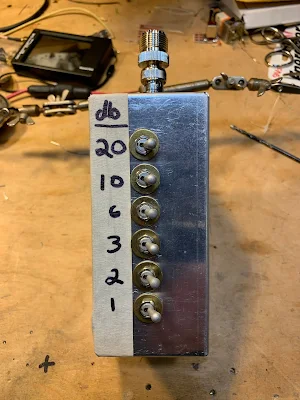
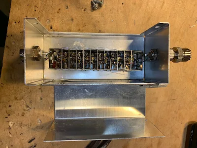
Fred, KC5RT, sent me an electronics "CARE Package" with lots of really useful stuff, including an attenuator with switches.  All I had to do was find a box and some connectors.  An appropriate box was quickly found in my junk box (TRGHS).  So Fred's attenuator was added to my attenuator arsenal -- thanks to Farhan for getting this started.  

I've already put Fred's attenuator to good use: Instead of building an RF gain control for my Q-31 receiver, I just put the attenuator between the antenna and the receiver.  

Thanks Fred!  


Monday, June 22, 2020

Feedback on Farhan's FB Feedback Amp Video


As I said a couple of days ago, Farhan has put out a very informative video on amplifier design. During the video we can see him determine bias, feedback and load levels, then select component values. We then see him actually build the amplifier "ugly style" and use his Antuino to test it.  Fantastic.   

Watch Farhan's video here:  https://www.vu2ese.com/index.php/2020/06/18/feedback-amplifier/


I sent Farhan some of my reactions to the video.  In the hope of stimulating some discussion, I repeat them here: 

___________________

Wow Farhan, I really enjoyed your video and learned a lot.  You definitely have the Knack for explaining this stuff. 

I have been struggling to understand feedback amps for a long time.  I took up this topic on pages 187-190 of the "SolderSmoke -- Global Adventures" book.  I was more focused on the benefits of FB amps, and on how and why feedback affected input impedance.  

 I took notes as I watched: 

-- I liked the fulcrum analogy. 

-- Really wonderful how you describe the selection of components to get desired bias. 

-- Even better when you explain tapping down of RF coil to get 50 ohms to look like 200 ohms. Great stuff. 

-- Standardized on BNC.  FB! 

-- .1uF caps.  Love them!  No argument here! 
 
-- I copied your resistor list.  Will use it with Mouser. 

-- Saving the pigtails.  Indeed!
 
-- I like your ugly "resistors first" technique.  I may have to move away from Manhattan. 

--  Wow.  Ugly circuits IN SPAAAAACE!  FB!
 
--  2N3904   I always think it is EBC when looking at the flat end of transistor with leads facing down. Only had reverse pinout with PN2N2222.  EBC is my usual assumption.
 
-- I still have the big box of trifilars you left me.  I use them.  Thanks!

-- I like that VTVM in your Antuino.   Very handy. Want one!  Also, We need to get the Antuino to go down to below 455 kHz. 

-- I also like your dual Return Loss and SWR display.  I think in terms of SWR.  Return Loss sometimes messes me up. 

-- Didn't know about the Hold and Zoom feature on Antuino. FB.
 
-- Your measurement of the Q of the crystal was awesome.
  
-- I checked my soldering iron temp:  I'm at 480 C   A bit too hot. Will back off. 
 
-- Good description of need for an attenuator at amp output to keep it in Antuino's range.
 
-- As I watched you tug on the components after the solder cooled, I remember an old and silly admonishment from the ARRL Handbook:  NEVER  use solder for mechanical connections.  Ha!  They were WRONG!
 
-- Demonstration of the flatness of feedback was great.
 
-- I found your measurement of impedance using the SWR feature of the Antuino to be very useful.  Is there a chart relating the SWR/Return Loss to actual impedance values? 

-- Loved your description of how output impedance affects input impedance.  That is why you advised use of TIA amps in my DIGI-TIA.   But now I'm thinking that if I can accurately measure impedances of non-TIA amps, I can design L networks that will keep the crystal filter passbands ripple-free, right? 

-- Great explanation of the benefits of the 6 db pads at amp output.  Allison often recommends this. Now I know why. 

-- Wow!  Now I KNOW what that two-tone box you left with me is for!  Now I understand how it can be used to measure IMD on FB amps.  I pulled mine out just as you began to discuss yours.  Really cool. 

Thanks a lot Farhan for doing this.   These videos will be of long-lasting use to homebrewers around the world.  I hope we will see many more VU2ESE videos like this one. 

73  Bill 

Friday, June 12, 2020

Software for Computer Interface with NanoVNA: NanoVNASaver


In the UK, "brilliant" is high praise indeed.  So when Tony G4WIF told me that the NanoVNASaver software was brilliant, I took heed. 

Being able to use the tiny (nano!) device with your computer makes it a much more accessible and useful tool, especially for those of us with fat-finger syndrome. 

The photo above shows the NanoVNA measuring Return Loss and SWR  on my 40 meter dipole. You can see the identical Smith Chart traces on the two screens. 

Download and installation was very easy. I got my Windows PC version from here: 

Other versions available from here: 

Coincidently, a fellow just today put out a video on how to use this software with the NanoVNA. 

Thanks Tony! 

Wednesday, June 10, 2020

Alan Wolke W2AEW Explains the Vector Network Analyzer (VNA) (Video)


I told Alan that his video on VNAs was -- for me -- very timely.  The video popped up on YouTube on the day than my NanoVNA was being delivered.  TRGHS. 

Alan does a great job in explaining what the VNA does.  Particularly useful for me was his explanation of the VNA's ability to measure phase differences (through the use of directional couplers).  

I am having fun with my NanoVNA, happily measuring SWR and the bandpass characteristics of various filters.  Mine came with what looks like a guitar pick -- this is used as a stylus to hit the small boxes on the touch-screen.  A nice touch...   

I wish there was some good software for use with this VNA.  Apparently the nice software described by Joe Smith (yesterday's blog post) is quite expensive.  Is there a free alternative out there? 

Tuesday, June 9, 2020

NanoVNA, Millen Dip Meter, Kilo-Megacycles, and Measuring the Speed of Light (Video)


Yesterday my NanoVNA arrived.  This morning I was looking for info on how to use it and I found this really wonderful video from Joe Smith.  

Wow.  Joe gives a really useful intro to the capabilities of this amazing little device. He even reaches back in time and compares NanoVNA results with those obtained by a Millen Grid Dip Meter.  He pulls out of his junk box an attenuator that is so old that it is marked in "Kilo-Megacycles."  (Shouldn't we revive terms like that?)

Joe also gives us a taste of what it is like to live and work in the GHz range.  He warns us never to touch the SMA connectors on our NanoVNAs (too late Joe).  And -- get this -- he uses a torque wrench to connect the little SMA coax connectors to the NanoVNA.  I'm not kidding.  A torque wrench.   Joe connects surface mount capacitors and inductors that have their values specified not only in picofarads and microhenries, but also at the specific frequency at which they were measured.  

My understanding of the Smith Chart was greatly improved by watching Joe's video. 

Icing on the cake:  Joe wraps up the video by using the NanoVNA to MEASURE THE SPEED OF LIGHT.  Great stuff.  Thanks Joe.  

Here is Joe Smith's YouTube channel:  
https://www.youtube.com/channel/UCsK99WXk9VhcghnAauTBsbg

Now I have to get the software to use the NanoVNA with my computer. 

Wednesday, May 13, 2020

Video on the Galaxy V VFO Project


This is the second version of this video.  I had some technical difficulties getting it to upload in High Definition, but I was able to work it out in this version. 

In this video I describe the VFO project, talk about how I made use of the e-bay Galaxy V parts, talk about the circuit (series-tuned Colpitts), conduct some stability tests, and discuss many of the ways a VFO like this one can be useful to the radio amateur.  

Thanks to Pete Juliano for inspiring this effort. 


Friday, April 24, 2020

The NanoVNA


Jenny List has a good article on Hack-A-Day about the NanoVNA.  

The ability to measure impedance would be very useful. 


Friday, April 10, 2020

Blog -- "Chinese Electronics Products Tested"


I was looking for information on my  FeelTech FY3200s Signal Generator.  I came across a very informative blog; it covers a variety of other Chinese gear and parts.  

Here is the Feeltech FY3200S article: 

https://chinese-electronics-products-tested.blogspot.com/p/fy3200s-function-generator-tested.html 

Here is the home page of the blog: 

https://chinese-electronics-products-tested.blogspot.com/

And here is backround information on the author: 


Thanks Jos! 

Saturday, February 29, 2020

How to Measure Output Impedance (video)


Thanks to Tony Fishpool G4WIF for alerting us to this very useful video by Alan Wolke W2AEW. 

Alan's video channel is a real treasure-trove for homebrewers.  

It was very cool to see "AEW" inscribed on the function generator that Alan built 30 years ago. 

Be sure to stay to the end of this video for some electronics humor from Alan.  (Steve Silverman:  Take note -- we might want to add this to the lexicon.) 

Now I'm going to search Alan's YouTube channel for a video on how to measure input impedance. 

Wednesday, December 11, 2019

Antuino Filter Analysis


Farhan had given me one of the early Dayton Hamvention models of the Antuino SWR/PWR/SNA RF test lab.  He later identified the need for a few mods to improve performance on that early model.  So I brushed up on my surface mount soldering, got the needed (tiny!) parts and made the mods.  I also put the battery pack inside the box and put some feet on the Antuino cabinet (it just seemed like the right thing to do). 

Antuino has already proven to be very useful as an SWR analyzer.  I know have a much better understanding of the SWR bandwidth of my wire antennas. 

And it is very useful in evaluating the passbands of filters.  I had an old 11.273 MHz filter from an old CB radio in my junk box.  I have no specs on this device -- I didn't know what impedances it was designed for.   So it was time for some Antuino technical detective work. 

First, take a look at the filter with nothing between it and the Antuino.  Input and output on the Antuino are 50 ohms, so here is what the passband looked like with 50 ohms: 


Next I put in two 47 ohm resistors, one in series with the input, the other in series with the output.  Antuino connected at the other side of each resistor.  Here is what it looked like.  Note the improvement in skirt shape.  But there is still a lot of ripple in the passband: 


Then I went to 100 ohms.   The passband ripple was reduced noticeably: 


Then up to 330 ohms.  Here the passband doesn't seem quite as flat as it was with 100 ohms: 


Finally, 1000 ohms.  Definitely too much.  Note the ripple. 
 

Farhan prefers the passband with the 100 ohm resistors.  I agree.  

BTW the filter is from TEW of Tokyo, Japan.  Model FEC-113-2  11.2735 MHz  No. 2   A    2
It had three crystals on the board with it:  11.275 and 11.272 -- these are obviously for LSB and USB.    The third crystal is at 11.730 MHz, indicating to me that they had a second IF of 455 kHz in this rig.   If I use it, I think I'd stay with single conversion. At 11.273 MHz the filter is of ideal passband width for SSB.  I do feel the urge to build something around this filter. 

Doing the mods on the Antuino was fun, and having worked on the device at least a little bit I feel more of a connection to it. 


Monday, October 21, 2019

Farhan Visits Northern Virginia and SolderSmoke HQ

Our good friend Farhan came to Northern Virginia last week for the 50th Anniversary Symposium of AMSAT.   We were really delighted that he also came to SolderSmoke HQ.  Elisa and I gave him a lightning tour of Washington DC (including a quick visit to The Air and Space museum) and then we headed back to the shack from some radio work. 

In the picture above you can see my BITX-20 (that Farhan designed) off his right shoulder.  Off his left shoulder you sits my ET-2 rig.  I really wanted to show Farhan how well the N0WVA regen performs -- he was impressed, especially when we started listening to SSB contacts. It was really amazing that we were doing this with just one J-310 FET.  This was great fun.  Farhan tells me that he will soon take up the "two transistor challenge."

When he was here in 2017, I tried to demonstrate my version of Rick Campbell's R2 Direct Conversion receiver.  Unfortunately, when I tried to show off the "single signal" capability that is the whole purpose for this receiver, it was NOT producing a single signal output -- you could hear the signal on both sides of zero beat.   One of the small AF chokes I had used had gone open, knocking our one of the two DC receivers.  This time I had the problem fixed and single signal reception was successfully demonstrated.  

Farhan brought me two pieces of test gear that I have needed for a long time:  A step attenuator and a two tone generator.  Paired with his Antuino, these devices will bring about a big increase in capability on my bench. 

It was really great to have Farhan in the shack.  We had a great time talking about ham radio and homebrewing.  Elisa and I both really enjoyed hearing from Farhan about his travels and about his life in India.  We are all really lucky to be in the same hobby as Ashhar Farhan. Thanks for the visit Farhan.

Here is a quick video of Farhan tuning the BITX 20.  


Saturday, August 3, 2019

Antuino Mods and Updates from Farhan


Both messages from the BITX20.io email group.

26 July 2019  

Peeps:


The Antuino has been in use for over a few months now. We had produced 100 of them that were sold at the FDIM. These work quite well for an SWR meter and Antenna Analyzer, but they were sub-optimal for serious RF work. For those who bought it for SWR measurements, you can continue to use it. For those who want to improve it, read on.

It was noticed that the db scale was not accurate. Antuino was designed to be an accurate and precise instrument. The db readings should be within +/- 1 db accuracy. However, they tended to vary by as much as 2 db on the upper range of power measurments. This was finally tracked down to having too much gain. I had prototyped the original with 2N3904 transistors but in production we used BFR93W as I guessed it would have 'better' performance. It turned to be a bad choice. The higher gain resulted in compression of signals above -30 dbm. This restricted the useful range of the Antuino to about 50 db. 

I am attaching the new (Version 2.1, it is a minor edit of the V2 that was sold at the FDIM). In summary, these are the changes:
1. The new software with a cleaner way to calibrate is on https://github.com/afarhan/antuinov2.1. Please upgrade to it even if you don't want to carry out the other hardware modifications.
2. Replace the Q1 and Q3 transistors to 2N3904. Although the PCB pads are SMT, you can solder the leaded type by twisting the legs around.
3. In the first IF amplifier (that immediately follows the mixer), we decrease the emitter resistor (R18) from 100 ohms to 51 ohms (you can also parallel a regular 1/4 watt 100 ohms with the original 100 ohms to get to 51 ohms). We also parallel the (R19) 220 ohms collector load with a 10 uh inductor (you can use 10 turns on FT 37-43), the exact value is not important.
4. In the second and third IF amplifiers, we replace the 100 ohms emitter resistors (R7, R34) with 10 ohms and remove the 4.7 ohm resistors (R32, R4).
5. In the last IF amplifier, we change the load resistor(R33) from 51 ohms to 220 ohms.

You need a few 10 ohms resistors and a 220 ohm resistor. You can resuse the R31 at R18.


Attached are the images and the circuit.

73, f 
_._,_._,_

August 3, 2019

Every instrument has limits on its accuracy. While making the Antuino, I was well aware of its deficiencies. 
I made a decision to keep it simple to a point where a radio ham could throw this thing together in an evening or two.

In order to overcome the limitations inherent in the Antuino design, the complexity could have been prohibitively complicated and expensive.
On the other hand, it is an extremely useful instrument that grows on you. I no longer use a frequency counter or the specan. I rarely use the oscilloscope. Antuino does most of my measurements.

There are two very important things you must be aware of while using the Antuino :
1. In the power measurement mode (the problem is non existent on swr or sweep mode), any reading above 25 mhz could be an image. Thus, if you see something at 35 mhz, you will have to do some mental math to figure out if it is not an image. An easy way to know is to add an external low pass filter with 25 mhz cutoff.
You have to use it like a radio in this mode. If you want to measure the harmonics from your pixie radio with 7040 crystal, tune to 14080, 21120, 28160 and measure. It is as accurate as any spectrum analyzer with more than 80 db of usable bandwidth. Raj and I struggled to get this for a month.
2. Unlike a full fledged spectrum analyzer, Antuino has just one bandwidth of about 7 KHz. This is enough to made IMD measurements at 20 KHz tone separation. The sweep plot does only 128 readings. Thus, if  you sweep a low pass filter from 0 to 20 mhz, it will measure the filter response every 120 khz. If there is something lurking between the steps, it will miss it. This is a common challenge with spectrum analyzers. So, a crystal filter should be swept at less than 100 khz. 
There is a software hack to mitigate this. First : introduce another control for step size. This can slow down the plot. A 30 Mhz sweep at 5 khz steps will involve 30 x 200 =60000 readings.It could take minutes. The Second : write a more optimal Si5351 routine that changes frequencies faster. I know that smaller jumps can be instantaneous on Si5351. I don't know that hack. If someone wants to take a stab at it, I am willing to work with them.

In a nutshell, Antuino is a very useful instrument. You don't have to buy it. You can build it. It is just as challenging as a direct conversion receiver. It does a fabulous job though. It can measure oscillator frequencies, it can measure amplifier gain, distortion, frequency response, it can measure filter response, it can show mixer behaviour, it can tune your antenna, it can measure power from a few uV to 100 mv and more with attenuators. It does all this slowly but surely. Like any precision tool, you must know its limitations and use them as an aware user. I would wager that if you have to choose just instrument for your lab, it would be this; Apart from a DVM.
And (I repeat) don't buy it, build it (grin)

- f

Designer: Douglas Bowman | Dimodifikasi oleh Abdul Munir Original Posting Rounders 3 Column