Podcasting since 2005! Listen to Latest SolderSmoke

Showing posts sorted by date for query CO2KK. Sort by relevance Show all posts

Sunday, April 28, 2024

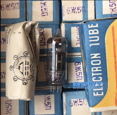
A Soviet Tube in Cuba: The "Little Spider"


I hope readers have picked up on the discussion of the Islander DSB rig out of Cuba. We had a bit of a breakthrough on this recently. I've been writing about it on the blog: 

https://soldersmoke.blogspot.com/2024/04/re-building-islander-dsbcw-rig-in-cuba.html 

One thing I think is especially interesting:  The Cubans were using parts taken out of old Soviet TV sets.  One of the tubes used in the VFO section of the Islander was known among the Cuban hams as "the little spider." 

Arnie Coro CO2KK explains why: 

"VFO is made with ONE of the 6 "little spider" 5 pentodes... By the way, I am sure you will like to know why the tube is locally known like that... the ZHE letter of the Cyrillic alphabet is something difficult to pronounce to a Cuban - or any other non slavic for the matter - and it resembles like a little spider on the tube's carton and... that's why it is not a 6 "ZHE" 5 but a 6 "little spider" five!!!"

Friday, April 26, 2024

Re-building the Islander DSB/CW Tube Rig in Cuba

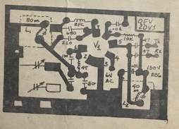
The VFO Board

The "motherboard" for an Islander
Islander boards recently obtained in Cuba by CO7WT

Pavel CO7WT is making great progress in re-building an Islander DSB rig, the same kind of rig that got him started in ham radio, and that was so popular in Cuba years ago.  Here are some background blog posts on this rig:  https://soldersmoke.blogspot.com/search?q=Islander  In essence, the Islander was the earlier tube DSB/CW rig; the Jaguey was a later, solid-state DSB/CW rig. 

When they get this Islander going, hams outside Cuba should definitely try to work this re-creation of an important rig. 

Thanks Pavel for all the information.  I will share with the group info that Pavel sent about temperature stabilization techniques used on this rig.  

Pavel CO7WT writes: 

Great news, today I received the package from my colleague in zone 6.

Two original islander motherboards and one from the vfo!

I'm doing a search among old technical friends in the city and in the country to see if I can put together at least a transceiver motherboard.

Audio triode-pentode is easy, as is tx pentode and audio double triode.

The difficult ones would be the 6cb6 and 6bz6 of the receiver... At least according to what I have polled among my local friends...

Tomorrow some friends are going to start looking for bases and valves that can be used to build a trx islander.

All out of pure nostalgia. I intend to make it qrp, that is, up to the output pentode, which there is between 3-5W of power, that is enough for me.

I am looking for alternatives for small sources, perhaps I will use switching for the filaments and we will see what I can get for the 180-250v of the plates.


Earlier: 

CO7WT here, built a pair of the Islander back in the time, the most scary part was the power supply.

The 600V is 300ish V from the transformed DOUBLED stright from the transformer and if you look closely on the diagram the doubling capacitor need to be of good quality otherwise it will explode in the spot.

As you can imagine, using scrapped parts means that very often this capacitor explodes, even after a few months of duty, that was a common problem.

We used to use 47uF/800v from Germany that was almost easy to obtain, but exploded like fireworks a given day.

Later I learned that if you put a resistor of about 1k 5W in series and work it for a while like this [no real voltage at the end] it will behave in the future and this trick saved many, a trick that was shared with Coro CO2KK and he found the explanation on the taming/training of the dielectric after storage/inactivity will prevent it from exploding.

I think he made mention this on a DXers Unlimited program...


Saturday, July 15, 2023

The Jaguey Five -- The Solid State Cuban DSB Rig -- Circuit Description

Obviously we need a picture of a Jaguey transceiver. 
"Made in Jaguey Grande" 

Trevor Woods found this report from Arnie Coro (SK) CO2KK: 

February 2009: 

Here is now item three in detail: It was quite a long time ago, when I heard about a nice project sponsored by IARU, the International Amateur Radio Union, that was promoting the design of a kit, a simple single band transceiver kit that could be sent in a small air mail parcel to radio clubs in Third World nations which could then deliver them to would-be radio amateurs, and help them build and align the radios... But, unfortunately I lost track of the project, and as many of our listeners may realize there is still a great need of such a project... Past efforts along this line have had some problems, among them the mistaken approach of using of very sophisticated electronic components that in case of a breakdown would be impossible to replace locally; and also, all attempts seemed to try to make the transceiver an ultra- or near-ultra-miniature radio, something that won't help at all with beginners...

So, when I recenlty received an e-mail from Canada, asking what I thought about reviving this great idea, our Canadian amigo asked what we had already done here in Cuba, with our JAGUEY double side band plus CW 10 watt transceiver that went up to REVISION NUMBER 5. , This was the last upgrade, done about three or four years ago, and we named it the Jaguey FIVE, as it generates 5 watts of CW... The Jaguey FIVE was a low parts count, not miniature, easy to build single band transceiver that used readily available components, instead of sophisticated state of the art parts...

In order to please the friend who wrote about this topic, here is a brief, on the air, description of our Jaguey FIVE and by the way, Jaguey is the name of a town, actually it is Jaguey Grande, or big Jaguey, and the Jaguey is a beautiful tropical tree... The original Jaguey transceiver originated in that Matanzas province town in 1982,

The receiver part starts with a simple yet effective RF attenuator, then it feeds a bandpass
filter made of two tuned circuits... we use shielded IF transformers from old TV sets 4.5 megaHertz audio chains... A simple bipolar NPN small signal transistor grounded base amplifier feeds a homebrew double balanced mixer... and we "discovered" quote, unquote, that the antenna balun transformers used in TV sets, the 300 to 75 ohms baluns, had a ferrite core with two holes that makes a wonderful broadband transformer for the double balanced mixer...

We use computer diodes removed from defunct ISA old computer cards and motherboards and developed a very simple test jig to match the diodes... The double balanced mixer is fed on the other port from a simple three transistor oscillator, of which we have two versions, one using three NPN bipolar transistors and the other one using an FET oscillator followed by two bipolars... at the output of the mixer we have AUDIO, as this is a direct conversion receiver, amigos!!!

Now we amplify the audio using discrete components and again we have two versions of audio filters, one with bipolar NPN transistors and the other using a very common operational amplifier IC... The audio power output stage also is available to the builder in two versions, one using discrete components and the other using an integrated circuit audio amplifier that is locally available here in Cuba and produces a booming 2 watts of audio, with a lot of gain and rather low noise! This is the audio IC used by the most popular TV set in use here in Cuba, so we were able to obtain them from the TV repair shops at low cost.

Well, that's why I will describe as a flexible design... again, no attempt is made to make the Jaguey single band amateur transceiver a miniature rig, as miniaturization is definitely not for beginners!!! And following up this description of the receive section of the Jaguey, in our upcoming mid-week edition of Dxers Unlimited, I will describe the transmitter section of the rig,that shares the same variable frequency oscillator with the receiver.... I think that a new more up to date version of the Jaguey transceiver could very well be made available in kit form, with large-sized and easy to assemble circuit boards. The old Version 5 uses three circuit boards, one for the receiver, one for the VFO and one for the transmitter, so the newcomer can assemble just the receiver and start listening to amateur radio communications before having his or her own ham license!!!

You are listening to the weekend edition of Dxers Unlimited coming to you from Havana on the air and on the web at our Dxers Unlimited blog.

----------------------

A video of Jaguey Grande, Cuba: https://www.youtube.com/watch?v=krblz_5o6jU

Earlier posts about the Jaguey on the SolderSmoke blog: https://soldersmoke.blogspot.com/search?q=Jaguey

Tuesday, April 11, 2023

Arnie Coro: Jaguey Rig Designed in 1982, More info on the Rig

Jaguey, Matanzas, Cuba

Dxers Unlimited's mid week edition for 23-24 October 2007

By Arnie Coro
Radio Amateur CO2KK
...

My own personal experience with the original JAGUEY direct conversion 
transceiver, designed way back in 1982, is that when used with a well 
designed front end input circuit, those receivers provide amazing 
sensitivity, with signals as low as 1 microvolt easily detected but, 
they do have one drawback, their selectivity or ability to separated 
between stations is very poor. The direct conversion radio receivers are 
used for picking up CW Morse Code Signals , Digital Modes and Single 
Side Band, but they are not good for receiving AM signals, and can't 
pick up FM modulated signals at all...

The original JAGUEY 82 Cuban designed single band amateur transceiver, was tested against a sophisticated and really expensive factory built 
transceiver. The tests showed that our design was at least as sensitive 
as the very expensive professional equipment, registering a measured 
sensitivity of less than one microvolt per meter, producing perfect CW 
Morse Code copy of such a signal. Adding well engineered audio filtering 
to a direct conversion receiver can turn it into a really wonderful 
radio by all standards amigos. 

Radio is a fun hobby, and believe me amigos, there is nothing more 
magical than listening to a radio receiver you have just finished 
building !!!

-----

Peter Parker VK3YE Found a nice description of the Jaguey by Cuban radio Amateur Jose Angel Amador from the BITX40 Facebook Group: 

A translation.  This was apparently in response to someone who thought they'd found a Jaguey schematic: 

"That's not an original Jaguey, that was a simple, single band, unswitched, 5 watt, DSB, kit for beginners with no gear and needing something to put on the license.
Carbon microphone direct to balanced modulator, two stages with 20 dB gain, W1FB/W1CER style feedback, and final with 2 x 2N2102 class B.
The receiver was more like that of the schematic, with a TAA263, easy to get from the FRC in 1978, and headphones. No need for an RF stage: the mixer was overloaded at night with European broadcasts above 7150.
The VFO is also inspired by Solid State Design for the Amateur Radio, a Colpitts with 2SC372 and a low gain feedback buffer with two 2SC372s.
Binocular ferrites were taken from Soviet TV baluns. The conditions of Cuba 1978.
Today I would make an SSB rig with polyphase networks, mixer with 4066,  and VFO Si5351.
The big complication of BitX is the crystal filter, they either get it made, or stick to a recipe, but few have what is needed to measure and tinker with crystal filters.

Sunday, April 9, 2023

Arnie Coro CO2KK (SK) Provides More Info on the Islander DSB rig

Peter Parker VK3YE found this message from Arnie CO2KK in the Wayback Machine.  We continue to look for more information on the Jaguey solid state DSB rig. 

Arnie wrote: 

Several years ago an amateur in central Cuba was approached by some of his young friends to help them build their first rig. CO7PR, Pedro, a telecommunications technician for the phone company, had a vast experience both with vacuum tubes and solid state circuits, plus that special gift of designing and building with whatever is available. After a few days, Pedro came out with the "Islander" prototype, a low parts count, easy to build single band transceiver!

Here is the circuit description of that little radio that has provided many cuban young and old, newcomers to our hobby, with their first rig... and the challenge to improve it.


RECEIVER:

It is a direct conversion, YES, a DC receiver made with vacuum tubes. The very thought of having those tube filaments fed from the AC power supply and at the same time having 80 or 90 dB of amplification made me shudder when I first talked to Pedro on the very popular here 40 meter band! You are LOCO Pedro, I told my good friend... CRAZY, those poor kids are going to hear 50 percent 120 hZ hum when they tune across the 7 megahertz band.

Yes Arnie, you are right, it has a little background hum, but by using a small loudspeaker and small coupling capacitors... it's tolerable! The receiver shares, in its original version, the same antenna input as the transmitter output stage, a PI network, but we soon learned to add a separate LC tuned circuit first and latter a bandpass double tuned input filter...PLUS a signal attenuator... a very primitive but effective attenuator... just a 10 k potentiometer!

For an RF amplifier stage the Islander uses a russian pentode, which is the equivalent of the popular TV IF amplifiers of the 50's... looks like a 6CB6, for those of you that fixed TV sets 40 years ago or so.

The 6 "little spider" five, as everyone knows that tube here,has a lot of gain, and it can be kept rather stable by a judicious choice of screen and cathode resistor values.. Noisy pentagrid converter follows!

The 6A2P... a russian 6BE6, was the first tube type used in the Islanders, later some people tried the ECH81 triode-hexode and found it works better.

The circuit of the 6A2P-6BE6 is quite straighforward... a... you guessed right... PRODUCT DETECTOR... fed from the vacuum tube VFO... and providing its audio output to the two stage audio amplifier.

Audio amplifier is made with a triode-pentode tube of which plenty are locally available from defunct TV's... the ECL82 and the 6F4P and 6F5P of east european and russian manufacture respectively provide a lot of gain.

So... that's your receiver.. quite straightforward, works on 160, 80 and 40 meters by just changing the input filter and the VFO injection, it does NOT provide very good selectivity at all, but during the daytime, when the 40 meter band is used for local and regional contacts, it puts those new hams ON THE AIR!


VFO... the big problem amigos!

CO7PR worked very hard to try to make a stable vacuum tube VFO... and he almost made it..

YES, ISLANDERS drift, some not too much, others are not so good, depending on who built the rig, and how close they followed Pedro's advice at first, and Arnie's CO2KK later (as yours truly became quite involved in the project, as soon as I found that it was THE way of getting all those guys ON THE AIR!)

VFO is made with ONE of the 6 "little spider" 5 pentodes... By the way, I am sure you will like to know why the tube is locally known like that... the ZHE letter of the Cyrillic alphabet is something difficult to pronounce to a cuban - or any other non slavic for the matter - and it resembles like a little spider on the tube's carton and... that's why it is not a 6 "ZHE" 5 but a 6 "little spider" five!!!

The VFO cleverly works at one half the operating frequency... and then it DOUBLES frequency at the plate circuit... output is via a link to the pentagrid or hexode mixer depending on which type you use.

BUT... the VFO also has a second output to the transmitting chain.. Well that's the receiver... OH YES... the VFO is fed from a VR tube, a gaseous discharge voltage regulator similar to a VR-150 or VR-105... CO7PR advises to use the VR105, but when building the Islander, special in the countryside, that's a very hard part to find, as old TV sets don't use VR tubes! So people use whichever VR they can find. ZENERS? They are only available locally for 6 to 24 volts, so they can't be used with this rig.


ISLANDER DSB AND CW transmitter circuit:

From the VFO plate circuit, you pick up 7 mHz energy (usually you must wait at least half an hour for that said 7 mHz energy to be stable enough in frequency) and feed two diodes (ex-video detectors from russian TV type D20) acting as what I like to call BALANCED AND UNBALANCED modulator!

When used for DSB, it is certainly a DSB generator... but when you want to work CW, it must be UNBALANCED.something easy to achieve with just a resistor from the +12 volts line and a switch!

The balanced modulator receives its audio from a carbon microphone capsule salvaged from an old telephone, and conveniently connected to same +12 volts with some additional filtering via biggest possible electrolytic + small ceramic dogbone from TV set IF amplifier as RF bypass... no dogbone capacitor there... strange howls on Islander audio as RF leaks into balanced modulator you know.

So dogbone ceramic capacitor is a must! No, disk ceramics are not locally available, so people must use the next best choice... dogbone ceramics in the 100 pf to 5000 pf range, usually rated at 300 volts or so... (that 300 volt rating we learned the hard way, but more about that later.)

The original version of CO7PR's Islander ran with the carbon microphone, no MIC LEVEL control option, as he really wanted to keep things simple... later versions have audio preamps of various designs, and some even have a sort of primitive compressor.. From the balanced modulator the DSB (plus a little carrier leak that is always there) drives the rig's one or two transistor low level RF amplifier, which is made using whatever NPN silicon transistor is available, usually KT315's salvaged from TV's too. the KT315 is sort of a russian version of the 2N2222, so you understand why we use it here!

RF voltage reaches then the grid of an ex-video output amplifier vacuum tube, and there you are... about 2 to 5 watts of either DSB or CW on 40 meters and a new cuban amateur ON THE AIR!

Before I forget... keying... a little chirpy always because of so many interactions between simple circuits, sometimes not too well shielded, first time builder etc.

BUT... ISLANDER is ON THE AIR providing that young kid from the local junior high school or that doctor that always wanted to be a ham, or maybe the fresh out of school electronic technician, with the fascination of their first ever rig. YES, they drift, and some drift badly, when the frequency determining capacitors in the VFO are not too good... (most of the time), as I said they are a little chirpy. and the receiver's selectivity makes working 40 meters at night almost impossible (although some wizards do make nightime contacts at the low end of 7 mHz) BUT. YES, they are ON THE AIR.

Today there are a few Islanders still on the air, and some are even still built brand new (with many of CO7PR's and CO2KK's mods), but the trend is for all solid state rigs centered around CO5GV's and CO2JA's prototype the "JAGUEY," a design that draws a lot from Wes Hayward's Solid State Design for the Radio Amateur, and as of late, with lots of ideas coming from SPRAT, the G-QRP club magazine and QRPp from NORCAL, the Norther California QRP club!!!

In a future posting I will describe the "Jaguey," too.

-------------

More info on the Cuban DSB and AM rigs can be found here:

https://soldersmoke.blogspot.com/2023/04/more-info-on-cuban-jaguey-solid-state.html 

https://soldersmoke.blogspot.com/2023/03/homebrew-am-from-cuba.html

https://soldersmoke.blogspot.com/2023/03/more-cuban-homebrew-from-80s-and-90s.html

https://soldersmoke.blogspot.com/2023/03/schematics-for-cuban-islander-double.html

https://soldersmoke.blogspot.com/2023/03/the-islander-homebrew-dsb-rig-from-cuba.html

https://soldersmoke.blogspot.com/2023/03/needed-more-info-on-cuban-islander-or.html


Friday, April 7, 2023

More Info on the Cuban Jaguey Solid State DSB Transceiver

ZL2BMI Transceiver Layout (not full size here!) 

Continuing our search for information the Cuban "Jaguey" DSB rig, Trevor Woods pointed me to Dick Pascoe's QRP column in the (below) July 1998 issue of Ham Radio Today.  I think the first SPRAT article about Eric Sears' ZL2BMI DSB rig was in SPRAT 83 in the summer of 1995.  This fits well with the sequence described below by Arnie Coro CO2KK. 

I am still looking for a schematic and pictures of the Jaguey rig: If you can help in this, please let me know.  


Wednesday, March 22, 2023

Schematics for the Cuban Islander Double Sideband Transceiver (Please Send More Info)

 
Jose CO6EC has been digging up 30 year-old Islander schematics for us.  Thanks Jose.  This one shows a VFO for the Islander.   Note that it runs on 80 meters, but they select the second harmonic at 40 meters.  This was a smart move that surely helped with VFO frequency stability. 

Jose sent this printed circuit board pattern for the VFO.  Obviously they were making many of these rigs. 

Here is the power supply.  Jose reports that the transformer came out of a Soviet Krim 218 TV set.  As a kid, I also pulled a transformer out of an old TV -- I did it to build a power supply for a Heath HW-32A. 

Here is another version of the Islander.  Click on the image for  a better view.  Jose reports that this version was circulating during the time Islanders were being built.  He says this diagram many have been done by Arnie Coro CO2KK (SK), and may have been circulated on the internet. 

Here's the first schematic that Jose sent.  Again, click on the image for a better view. 


I will continue to gather information on the Islander and the Jaguey.  If you have any info please send it to me.  

Here are some earlier posts on these rigs: 


Thanks to Jose CO6EC!  

Saturday, March 18, 2023

Needed: More Info on the Cuban Islander or Jaguey DSB Transceivers

CO6CBF: "I began operating on the HF bands using homebrewed radios. Mainly on CW running just 10 Watts. My very first phone transmitter was a controlled carrier AM modulator for the 160m band using tubes and components salvaged from an old TV set."

My good friend Dean KK4DAS has built a DSB rig for 10 meters and is working a lot of DX with it.  Peter Marks in Australia has also jumped into the DSB game.  A few of the students we are working with at the local high school may get their General Class licenses and convert their Direct Conversion receivers to Double Sideband transceivers. 

All of this has caused me to reminisce about the famous Cuban Double Sideband rigs. Homebrew Hero Arnie Coro CO2KK used to talk about these rigs on his "DXers Unlimited" program on Radio Havana Cuba.   But Arnie recently passed away, and with him I think a lot of the background info on the Cuban DSB rigs has also disappeared. I find very little about these rigs on the internet -- I have not been able find a single picture.  The Radio Havana Cuba archive of Arnie's shows has disappeared.  

Back in February I talked to Yulian CO6YI on 20 meters about the Cuban DSB rigs.  He said he had a lot of background info on them, and said he would try to send it to me.  I hope he is able to do this. 

The results of my initial Googling appear below.  There has to be more out there. I'm thinking that there must be a lot of background info on the Islander and Jaguey rigs sitting on the hard drives of radio amateurs.   It is time to give this info wider circulation.  Please send me any info you have on these rigs.  Of particular interest would be schematic diagrams and photos of the rigs.  


https://www.paara.org/newsletter/2000/graph200007.pdf


Date: Mon, 22 Mar 2004 17:48:59 -0500
From: "Prof. Arnaldo Coro Antich" 

Subject: Re: GB> 6EH7 vs. 6EJ7 as RF Amplifier

 Dear amigo Chris:
You are absolutely right !
EF184 is the best pentode for RF amplifier duty...
But, let me ask you something... have you thought
about the ECC88 and the even better ECC189 dual
triodes that were designed for TV tuner work, and
that incidentally were also about the last vacuum tubes
ever designed from ""scratch"" until Phillips and other
European manufacturers stopped from making
receiving type vacuum tubes.
The ECC189 is simply wonderful for a front end !!!
I am sure that you are aware of our limitations here at
my QTH regarding the possibility of obtaining solid
state modern devices... so we still make ""new"" ham radio rigs using mostly
vacuum tubes...
We even still make a version of "" The Islander"" a DSB transceiver with
direct conversion vacuum tube receiver...
Tube lineup is
EF184 RF amp
ECH81 product detector
ECH81 triode section not used
ECL82 triode audio preamp
ECL82 pentode audio output
6AH6  VFO ( Russian equivalent 6*5P )
Audio filter provided by good working brain of
operator !!!
Keep up the good work amigo !!!
73 and DX
YOur friend in Havana
Arnie Coro
CO2KK

http://ibiblio.org/modena/GLOWBUGSpiobaire/glowbugs.piobaire.weekly.html

Today’s first question came from a long time listener in India. Rajiv 
tells me that at this moment he is not able to pick up our station on 
the shortwave bands, and he rightly assumes that this is because of the 
very low solar activity… but Rajiv who lives in the garden city of 
India, Bangalore, the home of the nation’s electronic and other high 
tech industries, is able to read the scripts of the program that are 
made available to several short wave listeners clubs e-mail distribution 
lists. Rajiv tells me that he wants to obtain the electronic files of 
the Super Islander amateur radio transceiver to compare the circuit 
diagrams and design philosophy with a similar project that is becoming 
very popular among Indian radio amateurs.
Ok amigo Rajiv… I have already sent you all the files including some 
nice digital photos of the first prototype of the Super Islander, that 
as you will see, has two final amplifier options , one built using NPN 
RF power transistors, and the other one using two vacuum tubes that are 
very easy to find here in Cuba from recycled TV sets. The Super Islander 
is a single band transceiver that can be built for the 160, 80 or 40 
meter bands. Here in Cuba amigo Rajiv, the most popular amateur band 
nowadays is two meters, using the FM narrowband mode, and the second 
most popular band among Cuban radio amateurs is 40 meters, that’s why 
most of the Super Islanders are built for operating between 7.000 and 
7.150 kiloHertz.  The double sideband signal generated by the Super 
Islander simple circuit is very stable, and very few if any radio 
amateurs that contact stations using the Super Islander are able to 
detect that it is a double side band and not a single side band signal 
what they are hearing. One of the most outstanding features of the Super 
Islander single band amateur radio transceiver is that it is modular, so 
those who want to build it, are able to build and test each module as a 
single project, and after all the modules are fully tested, then they 
are easily wired together . The parts count, that is the number of 
components required to build a Super Islander was kept intentionally as 
low as possible, both to simplify its construction and to increase the 
reliability. I hope that amigo Rajiv in Bangolore , India will be able 
to make good use of the Super Islander’s files, and maybe even go ahead 
and build one , as the parts required are almost universally available, 
because that was one of the design requirements that I set when starting 
the  Super Islander project more than fifteen years ago….You can learn 
more about this simple amateur band transceiver by sending a request for 
the Super Islander files to arnie@xxxxxx … I will send it as a dot zip 
file and you will be able to see circuit diagrams, photos and full 
descriptions of the different modules of this nice little rig, that has 
proven itself under the most difficult circumstances, like handling 
emergency communications links during tropical storms.
http://www.hard-core-dx.com/hard-core-dx/2007/msg02587.html


Beginners generally build one of two radios; the vacuum tube Islander or the solid state Jaguey. The Islander is a DSB/CW Cuban design using a very clever low parts count circuit and a direct conversion receiver. The Jaguey, named for the Jaguey Grande Radio Club in Matanzas province, is a generic design, with a DC receiver, DSB and CW, using solid-state components. Many of its ideas are from Wes Hayward's W7ZOI's Solid State Design for the Radio Amateur. The lack of mechanical filters or quartz crystals to homebrew SSB filters made Cuban designers CO5GV, CO2JA and CO2KK choose a DSB and CW rig. Fitted with good quality capacitors for the VFO, it works quite well from a 12-volt car battery in hurricane emergencies.

Monday, January 9, 2023

Arnie Coro CO2KK -- Homebrew Hero -- Silent Key

I was sorry to read this morning of the passing of Homebrew Hero Arnie Coro CO2KK.  As we see in one of the obits, Arnie got his start in radio at age 12, with the gift from his father of a chunk of galena, a coil, and some headphones. 

Here are some of the SolderSmoke posts about Arnie:  

https://soldersmoke.blogspot.com/search?q=CO2KK

He will be missed. 


Monday, May 2, 2016

Hallicrafters S38-E Saved! it is not a "Pig with Lipstick." It Sounds Good! (Video) (And Radio Moscow recordings)


You guys know how it is:  You get tired of struggling with an old piece of gear.  You put it aside, thinking that you might never work on it again.  But it sits there in the corner, sort of looking at you.  A few days or weeks or years pass and you think, hey, I'll take one more quick look at this thing to see if I can get it going.

That's what happened to me this weekend with the Hallicrafters S38-E.  I hooked up the isolation transformer and put a fuse in the primary. I checked the wiring of my rewound antenna coil primary and found that I had connected it wrong.  Duh.   I then found that the antenna tuned circuit tracks fairly well with the tuned circuits in the local oscillator. 

I hooked it up to my 40 meter dipole and fired it up.  As evening rolled around the shortwave bands started to perk up.  The Chinese Broadcast stations were there, as was that fire and brimstone preacher Brother so-and-so.   But then I tuned into Radio Havana Cuba and the guy was talking about homebrew shortwave antennas.  Could it be?  Yes indeed.  It was Arnie Coro CO2KK.  The Radio Gods had spoken!  They clearly had wanted me to get this old rig going.

I still have a few things to do:  I need to fix the front panel light.   I want to put in a three-wire (with ground) AC cord.   Perhaps a real BFO (the original circuit seems to run out of steam with strong SSB signals).  And I need to spruce up the alignment on the 1.7-5 Mc and 13-30 Mc bands.

I think Pete and I may have been too harsh on this old receiver (calling it a pig with lipstick and all that).   It is clearly not a great communications receiver, but it is nice for casual shortwave listening. 

And here is a bonus treat for you guys: Remember Radio Moscow in the bad old days?  Yesterday I found a site with good recordings of some of their 1965 broadcasts.  This is  just what you would have heard coming out of an S38-E in 1965:


Tuesday, September 16, 2014

Regen Receivers in Cuba


Hola amigo Bill:

I was able to pick up the podcast with excellent audio quality.
It is quite true that regenerative receivers are very much in use
even today... for example many if not all of the automobile RF
keys opening and closing the cars doors rely on a superregenerative
receiver circuit !!!

The radio that you copied at the blog works very well indeed
but it would be  good idea to include a 5 kilo ohms volume
control.... Very easy to do indeed.

But let me tell you that my favorite regenerative receivers are
the classic ones, using vacuum tubes, and operating them
at voltages not higher than 50 volts... As a matter of fact many
tubes work very well at the 24 volts DC voltage level.
Using the classic Hartley circuit , there is no need for a hard to
find throttle capacitor required by the Armstrong circuit, because
the regeneration control works very well by using a potentiometer
to change the screen grid voltage of the detector.

I agree that using an RF stage ahead of the detector is always
a very good idea.... In my tubes regenerative I use a triode connected
6AK5 clone.... as a grounded grid stage....another 6AK5 clone ( the
6ZHE1P Russian tube ) is the detector and I use another 6AK5 clone
as the first audio amplifier then feeding an audio output pentode
all provided from a very simple basic 70 volts DC power supply.
BTW, using regulated DC on the filaments of the detector stage,
although a luxury by my standards is very helpful to reduce
hum .... 7805 regulator recycled from a bad motherboard, with
one 1N4007 from broken Compact Fluorescent Lightbulb inserted
in series with the regulator ground pin, produces a nice 5.7 volts
regulated DC that with a brand new tube is more than enough... with old
6ZHE1P recycled from Russian TV sets, you add another 1N4007 to obtain
6.4 volts regulated DC....

As said in the podcast, it is very important to do a very good
mechanical engineering job, place the main and bandspread tuning capacitors
away from the front panel, use isolated shafts between the capacitors
and the dial mechanism and make the front panel of a a thick steel
plate if possible.

There is a Dutch Cascode Regenerative radio that several Cuban radio
amateurs have built... it was designed with the amateur bands in mind so
the information about the tuning coils and capacitors lets you
obtain a very excellent bandspread on the ham bands.
I can send you that circuit that uses very common 12AT7-ECC81
and Russian equivalent double triodes.

Keep up the good work amigo and always tell us when the next
podcast is available. BTW it lasted for almost an hour !!!

73 and DX

Your amigo en La Habana, Cuba
Arnie Coro
CO2KK
Host of Dxers Unlimited radio hobby program
Radio Havana Cuba


Our book: "SolderSmoke -- Global Adventures in Wireless Electronics" http://soldersmoke.com/book.htm Our coffee mugs, T-Shirts, bumper stickers: http://www.cafepress.com/SolderSmoke Our Book Store: http://astore.amazon.com/contracross-20

Tuesday, June 7, 2011

Searching for the Sputnik Schematic

Mike, AA1TJ, has launched (!) yet another intriguing project. See below. In an effort to come up with the actual Sputnik schematic, I have thrown down the geek gauntlet to our fellow nerds at sci.space.history:

Greetings Space Historians!
We are a group of radio amateurs and we probably rival you in our
technical geeky-ness. We are now involved in an effort to re-create
and put on the airwaves replicas of the 20 MHz transmitters used in
Sputnik 1. (We will use the amateur radio 21 MHz band).
We are trying to find a schematic diagram for the transmitter. Can
you help us? Thanks.

------------------------
Gentlemen,

Arnie, CO2KK, told me last night that as a 15 year-old boy he'd made
it into the newspaper by picking up Sputnik's signal on his Hammarland
Super-Pro receiver.

Don Mitchell - a physicist now retired from the Bell Labs - also wrote
last evening to ask if I knew of a schematic diagram for the two
transmitters used on Sputnik-1. Mr. Mitchell maintains an informative
web site on the topic of Sputnik. Here, for example, is the link to
his page on the first of the series of "Travellers" to be lofted into
orbit in late 1957 into 1958.

http://www.mentallandscape.com/S_Sputnik1.htm

To the best of my knowledge the schematic for what may be the most
famous QRPp transmitter has never been published. It's a shame,
particularly as it would have been great fun to build an approximate
replica for use on the ham bands

However, I woke up this morning wondering why should we allow the lack
of an original schematic to stop us when there's plenty of descriptive
evidence available? "Spaceflight Magazine," for example, published a
wonderful article on the 50th anniversary of Sputnik. The story was
pieced together from original documents over a period of 20 years. You
may read the article here

http://faculty.fordham.edu/siddiqi/writings/siddiqi_sputnik_history_2007.pdf

"The two D-200 type radio transmitters operated on frequencies of
20.005 and 40.003 megacycles at wavelengths of 15 and 7.5 m. These
transmitters (which obviously used vacuum tubes) each had a power
intake of 1 watt and provided the famous “beep-beep-beep” sound to
Sputnik. The signals on both the frequencies were spurts lasting 0.2
to 0.6 seconds, and carried information on the pressure and
temperature inside the satellite; one set would transmit during the
“pauses” of the other."

"Despite objections from just about everyone, Gringauz insisted that
PS-1 carry a high frequency transmitter (the 20.005 MHz transmitter
operating in the decameter waveband) in addition to the VHF
transmitter (which had been commonly used on Soviet ballistic
missiles). ...In the end, Gringauz won over his opponents, partly
because everyone agreed that a high frequency
transmitter would ensure that the radio transmissions would be heard
around the world. The transmitter hardware was built by one
of Gringauz’ youngest engineers, Vyacheslav Lappo..."

>From other sources we know the transmitter used vacuum tubes rather
than transistors. This site mentions that when the received signal
level
was quite strong, the presence of a back-wave while the other
transmitter was keyed could be noted.

http://www.amsat.org/amsat/features/sounds/firstsat.html

The RF oscillator, at a minimum, must have been free-running. So,
we're talking a vacuum tube crystal-controlled oscillator and a PA
having an input power of 1 watt. They may have used a PA driver stage,
or perhaps a frequency multiplier stage. If they did use a multiplier
then it must have been allowed to free-run as well. But given the
battery drain considerations, I would have done my best to reduce the
number of vacuum tube heaters, or filaments to a minimum. As such, I
think there's a fairly good chance this was a simple, MOPA design
(oscillator-> PA).

I found what might be a photograph of the transmitter on page 26 of
the December 1957 issue of the Soviet "Radio Magazine." Perhaps our
Russian speaking group members can confirm this and provide us with
other clues appearing in the article text? The magazine can be
downloaded at

http://publ.lib.ru/ARCHIVES/R/''Radio''/

Click-on ''Radio'',1957,N12.[djv].zip. The "zipped" December issue
appears in DJVU format. Don't miss the nice Sputnik cover art.

This re-post talks about the center-fed Vee dipole used (the 15m
transmitter used the 5.8meter dipole) among other things.

http://hamradio.mybb.ru/viewtopic.php?id=625

Getting to get the point, this morning I woke up thinking about how
plentiful vintage Russian military tubes are these days. Remember how
inexpensive US military surplus used to be? That's how it is right now
with Russian components (and the characteristics of some of these
tubes are simply amazing). All I can say is get 'em while they're hot,
as it surely won't last forever.

It also came to me that Expanded Spectrum Systems sells an HC49
crystal cut for 21060kHz for two and a half-bucks each.

Finally, I remarked to myself that propagation-wise, 15m may well be
open for business come the 54th anniversary of the launch of Sputnik-1
next October the 4th.

You've probably guessed by now what I'm going to propose. We have
plenty of time to throw together a simple 15m CW vacuum-tube
transmitter having an input power of 1w or less. We could use any
tubes that we like but I'm going to build mine using 1950's vintage
ex-Soviet devices. I plan to power mine with one or two of those
ubiquitous 12V sealed-lead-acid batteries. I'll VXO my crystal and
I'll let it free-run during transmit; both for historical reasons and
to improve the signal quality.

Perhaps some of the antenna gurus here would lend a hand by modeling
and testing something akin to the original 70 degree Vee dipole? Would
this be a practical antenna?

I propose that beginning on "Sputnik Day" we launch our 1 watt Sputnik
clones on 15m CW. Instead of calling CQ, our call could be along the
lines of "Beep_Beep_Beep_Beep_Beep_Beep de AA1TJ". In other words, six
letter E's followed by our call sign. Given that I can barely organize
the socks in my underwear drawer, perhaps someone skilled at
organizing events would take up the cause?

One more thing. Poking around on Google last night, I was struck by
how many people remarked that the experience of Sputnik had changed
their lives. Some decided to become engineers, scientists or amateur
radio operators. I didn't know it at the time, but Sputnik changed the
way that I was educated. Not only did this little QRPp transmitter
make a tremendous impact on the world, but radio amateurs were front
and center. It seems appropriate that we should commemorate this
extraordinary day in the history of QRPp.

http://www.youtube.com/watch?v=CHaJDuq6tBM

(they were seeing the orbiting booster stage rather than the satellite)

Sputnik Mania...the complete film in two parts (warning...contains
some political "button-pushing")
Greetings Space Historians!
We are a group of radio amateurs and we probably rival you in our
technical geeky-ness. We are now involved in an effort to re-create
and put on the airwaves replicas of the 20 MHz transmitters used in
Sputnik 1. (We will use the amateur radio 21 MHz band).
We are trying to find a schematic diagram for the transmitter. Can
you help us? Thanks.


http://www.youtube.com/watch?v=8jI5RBRWIOE

If I happen to learn more about the original transmitter I'll be sure
and post it on my blog or web site. I found particularly interesting
the fact that WWV interrupted some of their 20MHz transmissions in
order to accommodate Sputnik's signal; a gentlemanly thing to do

As for the possibility of an event along these line, any comments or
discussion is most welcome. I plan to make a start on my little
Sputnik sender upon my return from vacation in July.
Greetings Space Historians!
We are a group of radio amateurs and we probably rival you in our
technical geeky-ness. We are now involved in an effort to re-create
and put on the airwaves replicas of the 20 MHz transmitters used in
Sputnik 1. (We will use the amateur radio 21 MHz band).
We are trying to find a schematic diagram for the transmitter. Can
you help us? Thanks.

Ha...I just received several fairly good-quality color photos of the
original Sputnik transmitters! At first glance it looks as though they
used two subminiature pencil tubes! The quartz crystal looks very
similar to our HC-18/u package. The RF portion is very simple in
appearance. In fact, it reminds me of something you'd find in a 1950's
ARRL Mobile Radio Manual! ;o)

The fellow who sent these apparently has a contact with one of the
original Sputnik (non-electronic) hardware designers; who is said to
be "still very much alive." My contact is going to make an inquiry
with his Russian contact about the transmitter.

Very cool...

73/72,
Mike, AA1TJ

Thursday, February 18, 2010

HOMEBREW HERO: Arnie Coro, CO2KK

I was getting ready to write a quick blog entry on Arnie Coro's latest contribution to ham radio (his idea to revive the old 40 meter novice band) when it occurred to me that Arnie's long track record of providing good ideas, technical advice, and inspiration definitely puts him in the HOMEBREW HERO category. Thanks Arnie!

Below you can find the transcript of Arnie's latest edition of Radio Habana Cuba's "DXers Unlimited." There is a good discussion of current solar conditions (improving!) and of Arnie's 40 meter CW initiative.

Arnie's work at RHC is archived and available on the net. It is a real Caribbean treasure trove for us: http://www.dxers-unlimited.dxer.info/

Here is Arnie's blog: http://dxersunlimited.blogspot.com/

From "DXers Unlimited" 16-17 Feb 2010:
Hi amigos radioaficionados around the world now enjoying the ongoing
upsurge in solar activity that has brought to us DX signals as
strong as we had not heard them since 2005 !!! Yes my friends,
finally, after waiting, and waiting, and waiting, we are seeing a
nice comeback of the sunspots... As a matter of fact, only two days
of 2010 had gone by with a totally blank Sun. The all important R
number from the very much respected Catania, Sicily reference solar
observatory was 39 yesterday... and two other sunspot groups are
just about to turn into view...
As a result of the sustained increase in sunspot count, we are
seeing the 15 meters or 21 megaHertz amateur band opening up every
day... I will tell you more about amateur radio Dxing later , here
at th emid week edition of Dxers Unlimited... The daily solar flux
is very near 90, and forecasters were looking at a lower flux during
the next three days, but this may change dramatically and in just a
few hours, if the new solar sunspots regions that are rotating into
Earth's view show high activity.
Item two: The amateur radio hobby is alive and in good health... ham
radio
operators are enjoying the hobby and finding new ways of
improving their communications skills... Here is a recent example,
by carefully studying the behavior of activity on the 40 meters
band, I was able to find out that the band
segment from 7105 to 7125 kiloHertz was seeing very little use here
in ITU Region II, that is the Americas. So I launched the idea to
start using that segment by low power stations, on several of the
popular ham radio Internet mailing lists. In just a couple days , CW
activity , mostly by low power or qRP stations on that segment
roughly 20 kiloHertz segment has increased dramatically... For many
operators, finding such a nice and clear , interference free
segment, has meant having the opportunity of making many more two
way contacts.... and not only exchanging reports, but also , thanks
to less interference, we have carried out some really nice ragchews,
and just notice that I have just said WE, because I am , of course,
one of the happy radio amateurs operating on CW between 7105 and
7125 kiloHertz.
There are no digital stations using that segment... as they are now
present between 7030 and 7040 kiloHertz, the two frequencies were
QRP , or low power operators, are used to gather, and where for the
past year or so, it has become extremely difficult at times to make
even a single two way CW contact.
I am not saying that QRP operators should abandon the two favorite
watering holes, 7030 and 7040, what I have told the QRP , GLOWBUGS
and Regenerative receivers Internet list members, is that the
segment between 7105 and 7125 is in a much better shape regarding
QRM... yes there is a let less interference from other
communications modes...so chances to make nice contacts increase in
a very significant way.
Si amigos , Yes my friends , Oui mes amis...amateur radio operators
around the world are now enjoying the upsurge in solar activity, and
with it, we all must look around the bands and find ways to make
better use of them... After all, many other users of the radio
spectrum are always monitoring the ham bands, just to have data
available to substantiate their requests for more spectrum space....
In other words, if we, amateur radio operators are able to be more
time on the air, and the bands sound like a beehive of activity,
chances that those spectrum hungry users will just go elsewhere !!!

The complete script of the program , devoted to the promotion and
development of our radio hobby in general and amateur radio in
particular, can be read at:
http://dxersunlimited.blogspot.com
later this Tuesday, after the program goes on the air

Comments , suggestions and ideas on how to help promote
amateur radio are welcome at my e-mail address
inforhc at enet dot cu

72 and DX
Arnie Coro
CO2KK
Designer: Douglas Bowman | Dimodifikasi oleh Abdul Munir Original Posting Rounders 3 Column