Podcasting since 2005! Listen to Latest SolderSmoke

Thursday, January 15, 2009

International Year of Astronomy -- 2009


Hey, the signals are electromagnetic. They are very QRP. And the receivers (well, at least the "amplifiers") are often homebrew. It's 400 years since Galileo spotted Jupiter's moons. To commemorate this, we have IYA2009. The organizers are developing a program to allow people to build their own simple telescopes, and are encouraging those who already have 'scopes to get out and let their neighbors take a look at the wonders of the universe. We did a bit of this "sidewalk astronomy" in London. We'll do our part for IYA2009 by taking our 6 inch Dobsonian out into the piazza here in Trastevere. Check out the project web site:
http://www.astronomy2009.org/globalprojects/cornerstones/galileoscope/

RADIO PIONEER: HAROLD BEVERAGE

I came across this interview with Harold Beverage, inventor of (among many other things) of the antenna that bears his name. I liked his description of the personalities and design methods of some the people he worked with (including Ernst Alexanderson).
Take a look: Beverage IEEE interview

Wednesday, January 14, 2009

Eldon's Beacon: GRABBED!

Last week we put out an all points bulletin for the new QRSS beacon of OM Eldon (scroll down a bit). Yesterday the signal was captured by Stu. Distance covered: 723 miles. Eldon's power out: 15 milliwatts. That's correct: fifteen milliwatts (Eldon had earlier calculated 150 milliwatts, but this turned out to be incorrect). Above is Stu's screen shot -- you can see Eldon's FSK signal: WAOUWH (read along the top of the square wave) at around 10140050 Hz.

Here is their e-mail exchange:

Re: Is this your QRSS beacon?
Tuesday, January 13, 2009 6:17 PM
From:
"Eldon"
To:
"Stu"
Thanks Stu, and thanks to Bill Meara and SolderSmoke.com
This is my my FIRST confirmed QRSS report from my first QRP rig, it is about 150mw into a North South 6 foot Loop about 6 feet AGL.
You represent it on about the freq that I think it is - without too much calibration on my part.
See: http://qth.map.googlepages.com/?qth=CN97BV43TU&from=CM87vk
Is your Grabber online?
Thanks for the report.
Regards, Eldon Brown - WA0UWH
Don't let the Zero land call fool you, I got it many year ago while in the Navy stationed at Denver, now located in Seven land near Seattle.
eldonb@ebcon.com

On Tue, Jan 13, 2009 at 12:39 PM, Stu wrote:
Eldon,
Copied the following screen shot on 30m today a few minutes ago – I think the FSK is your callsign – WA0UWH?
Copied with Spectrum Lab in CM87vk – TS-B2000 with 160m inverted L plus antenna tuner to load up on 30m
73's
Stu

Monday, January 12, 2009

KD1JV's Surface Mount Video

OK SolderSmoke fans, here's a video for YOU! Steve "Melt Solder" Weber has put out his first video. It is about surface mount soldering. It is all very interesting, and some actual solder smoke is released, but I was a bit disturbed when Steve put the PC board on an electric stove and then started using this purple thing that looked and sounded like a hair dryer. Made me yearn for my Weller soldering gun. Great video Steve, thanks!

Saturday, January 10, 2009

The QRSS Calibration Problem: A Proposal

Eldon's effort to be seen by the 30 meter online grabbers (see below) reminded me of the big problem I faced when I first built my QRSS beacon: getting my signal into the very narrow (100 Hz wide) QRSS frequency band. If you think crystal control will solve this problem, think again: Almost all of us are using crystal-controlled transmitters, but circuit and component variations can easily put your signal far outside the freq range that the grabbers are watching.

I was able to get into the band because I was able to find a conventional CW beacon fairly close in frequency to the QRSS band. I used IK3NWX on 10.141800 MHz. Knowing the frequency of this beacon (it was avalable on the web), I used the ARGO and Spectran soundcard programs to put my sigs where I wanted them to be. IK3NWX was useful because it was so close (within 2 Khz) to the QRSS band -- I was able to put both the NWX signal, and my target freq on the screen. Later, I built my "DaVinci Code" reference oscillator -- it serves as a freq reference that I can use (again, with Spectran) to get back in the band after working on my transmitter (for those times in which I can't hear IK3NWX).

It seems like a lot of guys in the US and Canada are now getting into QRSS. Many may face the same frequency calibration problem. Are the frequency readouts of the ubiquitous Kenwood/Icom/Yaesu rigs accurate enough to help? Do they go down to the tens of hertz range? I suspect they do not.

What new QRSS ops in the U.S. and Canada might need is the North American equivalent of IK3NWX's beacon. It should probably be fairly high powered (but 5 watts would probably do the trick). Conventional CW would be better than QRSS (it needs to be heard). The frequency should be outside but within 1-2 kHz of the upper or lower QRSS band edge. A station out in the Great Plains would probably be able to serve the large ham populations of both coasts. Perhaps we could arrange for the calibration beacon to be on at certain times (daytime on the weekends?). Of course, the key would be to employ a station with very accurate frequency measurement ability (down to 1 Hz) and a highly stable signal.

What do you guys think?

Friday, January 9, 2009

Eldon's QRSS Rig

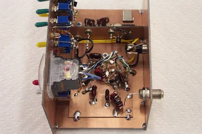
Eldon, WA0UWH, says the podcast inspired him to build some QRSS transmitters for 30 meters. His first effort was atop a 9 volt battery. The latest version has a more traditional enclosure. Eldon hopes to be seen on some of the grabbers -- please help him out if you can. In my case the hard part was getting the transmitter into the frequency band for QRSS (only 100 Hz wide!).

Tuesday, January 6, 2009

N0TU's Straight Key Night Video - 5 STARS!

Steve, N0TU, has put out a really great video on his Straight Key Night operation. It is really well-done. I was delighted to see both a Drake 2-B and a Heath VF-1 in use in Steve's shack. The video also has clips and photos from the stations Steve contacted during the event. Wow, a homebrew Spider! I remember that one from a 1993 issue of 73 magazine. You guys will love this video. Check it out: http://www.youtube.com/watch?v=aAk7gRdwpGs

Sunday, January 4, 2009

Mars Rovers Complete 5 Years on Red Planet

There is a very nice NASA video here: http://www.jpl.nasa.gov/video/index.cfm?id=795#

SolderSmoke 98

http://www.soldersmoke.com

January 4, 2009
New Year's in Rome, Fireworks, Abruzzo snow trip.
AA1TJ and the compact fluorescent bulb rig; "Michael the red-nosed Rainey, you'll go down in history!"
Billy's Asus eeePC : Amazin' piece of gear.
The Lure of Logic: Fixing my old Global Specialties counter (chip needed).
The Joy of Troubleshooting.
N3ZI's FB counter.
Balsa boxes.
Todd, VE7BPO, also getting logical.
Hans, G0UPL, back on 30 meter QRSS from London.
Lawrence, KL1X grabbing VK QRSS sigs in N. China.
My sigs steady in ON5EX grabber.
Dan's deals.
Book of the week: "Empire of the Air." Armstrong as a teenage ham.
MAILBAG:
Todd K5TAK on new name for Knack (no!)
Rick KC0PET has new 'scope, analyzer, Elsie
Bill N8ET Kanga USA getting going again.
Alan WA9IRS on Pete Millet's free online tech books
Wayne VA7AT on SDR
Frank VK2AKG is NOT the solenoid musician
Bill N3HQB was in Ade Weiss's summer camp ham class!
Roger K7RXV on shaving resistors
Dino KL0S on other free books on-line
Gareth G1DRG on BBC Digital Planet Podcast
Tim Walford's FB ham construction magazine
A word about words from our sponsors

Saturday, January 3, 2009

Homebrew Receiver from KC9KEP

Nice workmanship on this RX!

Thursday, January 1, 2009

My 75 Meter "Kickpanel" DSB Rig

I've been talking about it so long, I thought I should let you guys have a look at it. The box on the top is N3ZI's FB freq counter. It sits on the top cover of the TX -- the cover is made from the side panel of a dead computer that I found on a street in London. The metal cabinet is a "kickpanel" -- the kind of thing they often put on the bottoms of frequently used doors. Mine was purchased at Farmer Brother's Hardware on Fulham Road, London. One switch is for T/R. The other is for spotting (netting). I put the LED in there so I wouldn't forget to turn it off (and because Billy likes LEDs!) Circuit diagrams and LTSpice models appear in previous blog posts.

Moving inside, we see that the "chassis" is actually a kitchen cutting board, this one from a Dyas store in Windsor, England. In the lower left there's a board with the AF (mic) amp. Center front is the VFO box (elevated above the main chassis by wooden blocks in order to put the tuning cap in a comfortable position). The balanced modulator is on the left. The long rectangular board in the center-right is the 4 stage amplifier. Note the black wire suspended above the connectors -- that's an antenna for the oscillator -- it allows me to hear the oscillator signal with my Drake 2-B while in "spotting" mode (while putting the TX and the RX on the same freq.)

HAPPY NEW YEAR FROM ROME!

Wednesday, December 31, 2008

Free Electronic Books Online!!!

Alan WA9IRS alerted me to this technical treasure trove. Pete Millett is an engineer who, in his spare time, scans and uploads books about electronics that are no longer under copyright. Great stuff! Thanks Alan! Thanks Pete!
http://www.pmillett.com/technical_books_online.htm
Designer: Douglas Bowman | Dimodifikasi oleh Abdul Munir Original Posting Rounders 3 Column