Podcasting since 2005! Listen to Latest SolderSmoke

Thursday, May 20, 2010

Muntzing with Michael


Snappy title, don't you think? I think it could become a TV series, maybe if the Discovery channel someday gets into QRP and homebrew. In his QRP-L message about his latest rig, Michael, AA1TJ, said that he had "spent the morning 'Muntzing' G3XBM's, fine little XBM80-2
transceiver for the MAS (Minimal Arts Session) event." For those of you who don't recognize the verb "to Muntz", Michael is referring to one of the early manufacturers of TV sets, who, in an effort to reduce costs, ruthlessly went through his engineers' designs, throwing out every component that wasn't absolutely necessary. So I think Michael -- who I often refer to as the "Poet Laureate of QRP" -- has given us a new and very useful verb: To Muntz! (This comes in a month in which another very useful word was given to us: G3RJV's "socketry.")

Michael said, "I felt like the guy in the movies yesterday; throwing everything overboard that's not absolutely necessary in order to keep the Zeppelin/balloon aloft long enough to make landfall. :o)" The results speak for themselves. The schematic above and the picture below show Michael's entire transceiver. And he made a bunch of contacts with it.

One word of caution: Minimalist radio is not for the faint of heart. As the parts counts go down, the degree of difficulty for successful contacts goes up.

Check out Michael's page: http://www.aa1tj.com/Menos es MAS.html

Here's a picture of the rig:

Tuesday, May 18, 2010

YET ANOTHER HB DSB QRP WSPR Station! And more "inverted FSK"!

Paul, M0XPD, reports that he has joined the DSB revolution and has put a homebrew DOUBLE Sideband WSPR signal on the air. The rig is pictured above. So I can no longer claim to be the ONLY DSB WSPR station in the world. FB Paul. For more details go to Paul's site:
http://m0xpd.blogspot.com/2010/05/homebrewed-whispers.html

This was the second time in a week that I've found someone else doing the same nutty thing that I've been doing. The first incident involved G0XAR. I found him transmitting upside down FSK on 30 meters. Again, I am no longer alone...
Note that both of my colleagues in radio eccentricity are from Britain, a land that takes justifiable pride in its eccentric boffins!

Sunday, May 16, 2010

"It's all your fault!"

Lulu just announced free shipping on the book (to U.S. addresses only) for the whole summer. Starting now. But before you order, consider these words of warning from one reader:

Bill,

I just finished your Soldersmoke book. I really enjoyed it - but...

I got the radio and electronics bug a bit late and was 23 years old before I got my ham license. I was truly fascinated by it all. Then I started wanting to learn why it all worked. It was truly a challenge to start figuring out how electronic circuits work with nothing more than my average intellect and a few books. I strained my gray matter over the electrons and P and N type material. Finally I decided to ignore it and move on - just put the 'trons into the black box and pick them up on the other side. I eventually became proficient enough to build kits and do some basic troubleshooting. I had SSDRA and a bunch of stuff by Doug DeMaw, but never could get too deep into it. Eventually I had what I believe was a neat miss from lightning and station KC4GIA went silent for a number of years.
Then I found your podcast. I've really enjoyed it. I've slowly started getting back on the air. I've bought my old dream rigs (Drake Twins, B line) and built an ATS3B. But the urge to learn more and progress to the true homebrewer level has taken hold. It's all your fault. I blame you completely. I now have a copy of EMRFD, the latest ARRL Handbook, and even have started trying to figure out LTSpice. Ok, that's also the fault of the Hands On column in QST.
I do have to thank you for the excellent descriptions of the electrons moving through P and N material. I actually think I've got it now. Now if I can figure out all this biasing, and impedance matching, etc. I might get somewhere. Your description of how you have to match impedance through different stages makes sense, but I'm still fuzzy on how to determine the impedance in the 1st place, etc. I'm truly excited by the possibility of learning how to design circuits on my own rather than building by rote. Again - it's all your fault.
Back to the book. I really enjoyed the story of the 17M DSB rig you built in the Azores. It was like an adventure story. Very cool. I'm still a bit vague on why DSB, but you seem to like it, so whatever moves you my friend. I am also intrigued by the satellite contacts. I had always thought you had to spend a small fortune on an az-el rotating antenna array. I'm looking forward to trying it out with normal antennas. My only satellite contacts have been through RS-12 (I think that's the right number) using the 15 and 10 meter bands. I don't think there is anything out there using that mode any more.
I also find it fascinating that a guy who used to live a little over an hour from my QTH in Winchester, VA and is now halfway around the world has had such an impact on my enjoyment of the hobby. If you do end up back in the DC cesspool, I hope to get the chance to meet you.

Final thought - Audio Book! I'm used to you talking to me. There ought to be a way to sell a download or something. I think the book is awesome, and may even become a scribbled in resource at some point, but an audio version would be a good companion to the print version. Just a thought...

Thanks for the motivation. You've brought me back to what's fun in Amateur Radio - learning!

Mark
KC4GIA

Saturday, May 15, 2010

Physics, Math, and Futurama

My kids watch this show. Here's an interesting article about the writers and their science/math backgrounds:
http://www.aps.org/publications/apsnews/201005/profiles.cfm

Friday, May 14, 2010

The Death of a 2N3904: Captured on Grabber Video!

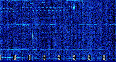
On Sunday I was working on my little DaVinci QRSS transmitter. I had it on, happily generating FSK on 30 meters. Then all of a sudden I noticed that power out had dropped to zero. I suspected a blown final transistor -- this was before the installation of my elegant Altoids smoke-stack heat sink, and the little 2N3904 I was using in the final was getting quite hot (it runs Class A). Almost instinctively, I turned to the ON5EX grabber. The image from Johan's receive system captured the final moment of that transistor. See that bright spot where the square wave ends? That's when the transistor blew. I tested the 2N3904 out of circuit: the base-collector junction is now completely open (no current in either direction). The death of this transistor may also have been related to the intermittently bad 4700 ohm resistor in the bias circuit. The 2n3904 has been replaced by a more robust 2N3053 sent to me by AA1TJ. It is protected by the Altoids smoke-stack heat sink (scroll down for schematics and an image).

Hope everyone is having fun at Dayton. I caught G3RJV's talk yesterday via streaming video. As always, inspiring stuff! And I really liked a word he used: socketry. You know, "the PC board, and the box will all the associated SOCKETRY."

Wednesday, May 12, 2010

Schematic for QRSS Transmitter

Here is the schematic for the little QRSS (visual) transmitter that is currently rockin' Europe's 30 meter band with an AWESOME 20 milliwatts of SLOOOW FSK. (As I type, it is 0415 UTC, 0615 local, and the first signs of my signal have just appeared on the ON5EX grabber up in Belgium.) The FSK modulation comes from Hans Summers' multivibrator circuit (see earlier posts).

It was a lot of fun to take this thing very quickly from LTSpice, to the workbench, then to the antenna, with Johan's grabber providing instant feedback. This started out as a one-stage Colpitts oscillator transmitter. But I needed more stability. Indeed, the separate oscillator with the source-follower buffer makes it much more stable. Before, any adjustment to the antenna tuner shifted the frequency. At one point I even suspected that wind blowing the antenna was shifting the frequency -- we are talking about a band that is 100 HERTZ wide, so even a few hz of instability is noticeable. But I find that crystal ovens and other extraordinary measures are not really necessary.

I had one unusual problem with this little rig: As I was doing my initial tests, I noticed that the output signal was sort of jumping up and down. The problem was in the PA. I isolated the problem to the base circuit. At first I thought that some small blob of solder was intermittently messing up the bias voltage (that's quite possible here in the N2CQR lab!). But no! It was that 4700 ohm resistor. It was bad, and kind of intermittently bad! I never had a resistor go south on me like this. It is an ordinary 1/4 resistor. It is not dissipating a lot of power.

I'll keep it around 10140010 today. Check it out on Johan's grabber:
http://www.on5ex.be/grabber/grabber.html
Look for a horizontal lines with little bumps (about 4-5 per minute). That's me.

Tuesday, May 11, 2010

The DaVinci Altoids LED 30 Meter Multi-vibrator MEPT Transmitter

Hey, check out the Altoids heat sink for the PA in my little 30 meter MEPT rig. Is this a new use for our beloved Altoids tins? I like the smoke-stack look.

This rig has evolved quite a bit. It started out as a frequency standard for QRSS and was mounted inside a paperback copy of Dan Brown's book. Then I matched the oscillator up with the multi-vibrator pattern generator from one of Hans Summers' rigs. This week I decided that I really needed a buffer and a PA -- I needed a bit more stability. I'll try to post a schematic tomorrow. In the meantime, watch for my little signal on the ON5EX grabber (off to the right). The pattern is small (3 Hz) bumps, about 4-5 per minute.

Saturday, May 8, 2010

First Transatlantic Transistorized QSO

1956. 80 mW on 20 meters. U.S. to Denmark. Above, the rig that did it.
The online Transistor Museum has a wonderful new article about this historic event, with details on the rig and the operators. Check it out:
http://semiconductormuseum.com/HistoricProfiles/Raytheon_TransAtlantic_Transmitter_Profile_Index.htm
Thanks to AA1TJ for alerting us to this.

The Limerick Revolution

On the last podcast I mentioned a new PC board technique being pioneered by Rex, W1REX, out of Limerick, Maine. The Limerick technique uses cool-looking black PC boards with pads for the components. (The picture above is the kit version of AA1TJ's famed Reggie receiver.) Connections between the pads are via PC board traces within the board. I like it because it seems to provide the big advantage of our beloved Manhattan technique: you have all the parts and connections topside. Check out Rex's fine line of kits: http://www.qrpme.com/

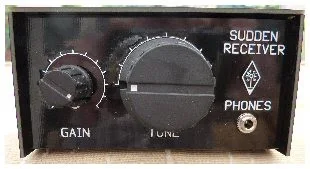
Today G-QRP club announced the release of a Limerick kit version of G3RJV's Sudden receiver.
Take a look at the final product and the boards:

Very nice. Read more about this wonderful kit here: http://www.gqrp.com/sudden.htm

Go Limerick! Go Sudden!

Thursday, May 6, 2010

QRSS LED FSK Experiments: More Blue vs. Red

On my little Colpitts/DaVinci/G0UPL less-than-10 mW QRSS rig, I started out with a forward biased (downward pointing) Superbright Blue LED (from AL7RV). (Refer to Hans' schematic, above.) You can see the resulting pattern below. That is my signal above that of Alan, VK2ZAY. At first I thought the diode was just switching in the 5 pf cap, but Hans (who knows this turf far better than I) thinks it is more of a varactor action. I now think it is a little of both: When that + 2.5 volts from the multivibrator hits the diode, it goes partially on (it even glows a bit). This puts the 5 pf cap into the circuit (through the resistance of the diode). The diode itself increases in capacitance because of the increased forward bias. As a result, the total capacitance increases, and the frequency drops a bit. Thus, forward-biased diodes result in upside down FSK. You can see a bit of the varactor action in the curve on the trailing edge of my not-so square waves -- I think that marks the period in which the voltage from the multivibrator is slowly rising:

Just to make Hans happy, I switched from a forward biased blue to a reverse biased (upward pointing) red diode. The resulting pattern (below) looks a lot like the pattern shown in the picture in Hans' excellent SPRAT article. This is clearly FSK. The positive voltage from the multivibrator increases revers bias on the LED, DECREASING capacitance and RAISING the oscillator frequency. In the curve of the leading endge of the pattern you can see the voltage from the multivibrator slowly rising. FSK here is "right side up."

Finally I tired a little 1N914 diode forward biased. I was hoping to see some cleaner switching action, but even with this little diode you can see quite a bit of varactor action at work:

I think the switiching would be a lot cleaner and more complete if the voltage from the multivibrator wasn't coming through a 1 meg resistor. But when you put a lower resistance in place of the 1 meg ohm part, you start to mess up the frequency of the multivibrator.

I have to say, my favorite pattern is that from the Blue diode forward biased. Sorry Hans. To each his own...
I'm guessing that AL7RV went to Michigan...

Thanks to Johan for the ON5EXcellent grabber which is visible over here>>>>>>>>>>>>>>>>>>>

Wednesday, May 5, 2010

Altoids to the Max!

Rogier, KJ6ETL, sent an interesting link to some inspirational projects involving Altoids tins:
http://blog.makezine.com/archive/altoids_and_tin_cases/ The first one that appears seems to belong somewhere else -- just scroll down to find the tins.

Wiki provides background info:

Altoids are a brand of breath mints that have existed since the turn of the 19th century. Altoids are less widely available in Britain—their country of origin—than in the regions to which they are exported, the standard peppermint mints being the only flavour available and only stocked in relatively few stores. Callard & Bowser-Suchard manufacture and produce Altoids at a plant in Bridgend, Wales, although Wrigley, the brand's owner, announced in mid 2005 they planned to move Altoids' production to an existing plant in Chattanooga, Tennessee, in order to manufacture its products closer to where they are sold.

The history of Altoids dates back to the reign of King George III. The brand was created by a London-based Smith & Company in the 1780s but eventually became part of the Callard & Bowser company in the 1800s. Their advertising slogan has been "The Original Celebrated Curiously Strong (insert flavour here) Mints" for a number of years, referring to the high concentration of peppermint oil used in the original flavour lozenge. The "Story of Altoids" text is printed on the paper liner inside certain tins.

---------------------------------------------------

One cautionary note: Apparently Altoids mints played a minor role in the Bill Clinton-Monica Lewinsky mess. We won't go into the technical details here, but suffice it to say that a collection of Altoids tins on your desk at work may raise some eyebrows among some of your colleagues.

Monday, May 3, 2010

Soldersmoke Podcast #124

That's Billy on the right
May 3, 2010
Oprah follow-up: On to Martha Stewart and Dr. Phil?
Fencing on a Roman piazza
Breaking an important cable
My WSPR Direct Conversion receiver
Roger Hayward's wonderful ugly AF amp circuit
The beauty of SBL mixers
My DaVinci Code Oscillator goes on the air!
Making my own 555 timer chip (sort of)
LEDs as varactors (or are they colorful switches?)
Black Holes in workshops -- is the LHC to blame?
Altoids: now made in TENNESSEE!
G3RJV's wonderful video
MAILBAG
Designer: Douglas Bowman | Dimodifikasi oleh Abdul Munir Original Posting Rounders 3 Column