Jim W8NSA ex AL7RV is an old friend and a really talented radio builder. Over the years he has sent me many boxes of very FB radio parts. I'm sure that almost all of my homebrew rigs have parts from Jim somewhere in the circuitry. Jim recently sent in an update on his radio building efforts.
Bill,
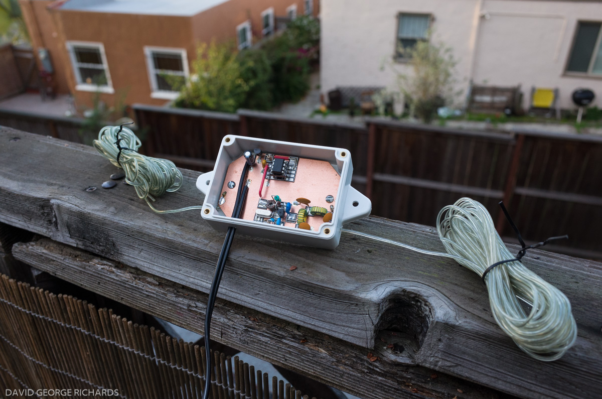
I managed to cobble up some regen's over the summer. Most fun was my version of Dave Richards, AA7EE Sproutie, it turned out so nice I have it on my bedside table. Yes, the Sproutie has displaced the trusty old Transoceanic, brings back memories of late night SWL'ing with my Space Spanner as a teen.
The Sproutie worked well enough I'm considering a build of the Dave's Sproutie MK II, maybe not in such a grand cabinet or with such fine metal work as Dave's but a functional copy.
I also built the regen receiver from the SOE Paraset design, other then a coil winding mistake the receiver worked well at power up.
I built the Paraset receiver to test a number of mods others have suggested to improve the receiver's performance. Using the mods involves modern solid-state components and additional band-spread functionally. Many consider the mods be in poor taste but they go well making a much better receiver.
I am ready to build my copy/version of the Paraset, now that I've missed SKN I have almost a year to get it built.
I've been gathering Paraset parts for years, was lucky to get in on the group purchase for a set of 3 Paraset knobs made from the same molds by the same company SOE used when building the transceivers in the 1940's, having a real part of that history is exciting, to me at least.
Paraset Parts (see picture above) (some parts shown may not be in the proper location)
At last I have all the major components. I am at the point of gathering up the various resistors and small fixed capacitors needed. Some builders have gone to the efforts of embedding newer, smaller, parts in the carcass of vintage 1930s & 40s parts hollowed out and repainted. Too much effort for me, I want a functional radio, not a museum grade replica, but I really do want to keep the look of the SOE issued set.
Case and front panel...
Many of the U.S. Paraset builders are using a wooden craft box from Hobby Lobby, It is just about the correct size and shape. You can see at the right side of the photo a detailed panel layout. Building the Paraset is not quite Heath Kit but with so many talented builders having made so much information available I feel so lucky to follow the effort.
Years ago, during our RV travel days, I picked up a box of Bliley AX2 40 meter crystals. Good price and just about every one of the crystals were found to be working. Have a total of eighteen 40m crystals from 7.0024Mhz to 7.0986Mhz, have two 80m crystals in the CW portion but none of the AX2 crystals are for the traditional QRP frequencies, close but... AF4K and others are selling HC49 crystals for the QRP frequencies, problem is the 6L6/6V6's used in the Paraset are known to be real crystal crackers.. (as was my 1964 novice rig!).
I'm considering the use of a transistor oscillator and driver stage to feed the 6L6 as a PA in effort to save the crystals and maybe allow the use of an outboard DDS VFO, yes I can hear the moans of dismay from other Paraset replica builders
The box included a number of sockets and crystal adapters too. Was great find. Having so may 40m crystals I'm starting to have thoughts of optimizing the Paraset build for just 40 meters. I can improve the sets performance but of course lose 80m and possibly 60m.
Today's project while catching up on SolderSmoke Podcasts is a test device to aid in checking the resonant frequency of L/C networks. It's always nice to prove your math is correct!
Building it Manhattan style into an old rat shack plastic box.
I have always loved the way WW II equipment had the schematics varnished into the covers or cases. I try to do the same with most of the things I build.
Schematic reduced to fit, ink-jet printed. Using an old credit card I spread a very thin layer of E6000 clear adhesive on the case, apply the paper image, then using a clean credit card or the edge of piece of circuit board feather the schematic into the adhesive.
Let dry for about 10 mins, wipe off the excess glue around the edges. Let dry for 24 to 48 hours and cover with a few thin coats of Testors Clear Lacquer Overcoat.. several thin coats, follow the recommendations for re-coat time on the spay your using.
Please read the cautions for using E6000. Pete may not be able to purchase it in his state!
The Paraset antenna output connections use a porcelain crystal socket, the AX2 crystal purchase included a few dead or empty crystal cases, I modified two of them to use as adapters.
Thanks again to you and Pete for the blog and smoke efforts!
73, Jim W8NSA aka AL7RV


