Podcasting since 2005! Listen to Latest SolderSmoke

Tuesday, July 21, 2020

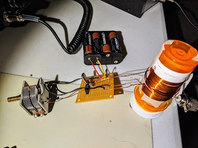
A Quarantine Mighty Mite


'Tis a thing of beauty. 

Bill/Pete:
    I just decided here over the COVID period to head back to basics here and build a Michigan Mighty Mite with a Color burst crystal I had here. And wouldn't you know it, it works!  Here's a couple of pictures, it's not pretty at all. Needs to be mounted on something. 

Don KC9ZMY


Sunday, July 19, 2020

Knack Story -- Tom WX2J

RTTY Model 15

Hello Bill,

Greetings from a fellow ham in Northern Virginia. I have enjoyed the SolderSmoke podcast for a few years now, and I just heard your recent presentation to the Vienna Wireless Society. We have a lot in common so it is about time I reach out to make your acquaintance.

I was born in NYC and grew up in Northern NJ. I was first licensed in 1969 as a high school student (51 years ago! Goodness!). My novice callsign was WN2JFX, and I progressed from Novice and then to General and Advanced as WB2JFX, and then eventually to Extra (in about 1990 -- while the 20 WPM code requirement still existed). At that point I put in for a 2X1 callsign and received WX2J, which is a nice twist on my original call.

I was fanatically active in my early years in ham radio. My Elmer (George, K2VVI, SK) set me up with a DX-40, and my parents provided a brand new Hallicrafters S-120 (you could copy the whole 40 meter band without changing the frequency!). I think I Worked all States as a Novice and learned that the human brain is the most amazing audio filter on the market. When I made General, George lent me an old Hallicrafters SX-25, and then I was really in good shape. Besides CW, I was also very interested in RTTY. I had my own Model 15 leaking oil in the basement and had a blast watching the magic of that thing printing messages out of thin air. I have always been a home-brewer, and one of the first serious things I built was a two- or three-tube RTTY demodulator from the Handbook. Aluminum chassis, chassis punches, tube sockets -- the whole works. I have no idea what the real inductance was of the inductors that went into the filters but somehow if the signals were strong enough, and on 850 Hz shift, it could actually demodulate signals. I probably still have that thing around here somewhere.

Another local ham bequeathed me his entire collection of 73 magazines - 10+ years starting with the first issue (~1960). I read them from cover to cover so many times I probably have them memorized. I became a real fan of Wayne Green, W2NSD, who was always ornery and controversial but a very interesting guy. I met him at a hamfest many years later and we had a great chat.

In any case I wanted to mention some other things that resonate with me as I listen to your podcast. As a kid growing up in the shadow of NYC in those years, you can bet that the Jean Shepherd broadcast was a regular part of our life. My dad used to listen to it every night -- 10:15 p.m. I believe, on WOR -- and we both used to greatly enjoy his stories of lighting up the fuse panel and nearly blowing up the house as he and his old man were playing with radios, etc. It was a common theme in our house too when my ham radio signal would blast into the TV set or I dangled new antenna wires off the house and out of the trees -- "You're going to blow this house up!" I studied electrical engineering in college and was commissioned in the Air Force upon graduation. I served a 20-year career in the Air Force and stayed somewhat active in ham radio. I was licensed and operated out of Okinawa (KA6TF) and England (G5ERE) during tours of duty in the early 1980s. Always an HF guy, in about 1982, in Japan, I bought myself a new Icom IC-720A, and this is still my primary rig. I was an early adopter of PK-232 and did some extensive building and experimenting with it. Sadly though, in the last 25+ years, my ham radio experience has mostly been vicarious as my work and family obligations have just not left much time for ham radio. I do have a G5RV wire antenna strung up but very rarely jump on the air -- sometimes during contests.

In high school we made a field trip to ARRL HQ in Newington, CT. While there we did all the things people do on such a visit, but one of the high points for me was meeting Doug DeMaw. I can just hear how Shepherd would describe it -- "I turned the corner and there he was! In person! The high priest of homebrewing! Doug DeMaw. In the flesh!" Cue the kazoo. I actually also met Shepherd at a book signing (Wanda Hickey's Night of Golden Memories?). I remember presenting him with a computer-printed banner of his callsign -- K2ORS -- produced by one of the few functioning computer programs I had written in high school. I also heard him on the HF bands one night -- I think he was in Florida -- and actually made contact with him, if barely being able to exchange callsigns can count as a contact.

Well, more than you wanted to know. I just wanted to let you know that I enjoy your podcast and can personally relate to very much of what you say. Although I am steeped in Hardware Defined Radio, I am also a software guy so I expect that my future includes SDR. I hope you and Pete are able to continue the podcast for a long time to come because I need the full HDR-SDR spectrum to be covered -- hi.

73,

Tom Fuhrman, WX2J

Saturday, July 18, 2020

Overcoming the Complexity of the Michigan Mighty Mite: Walter's Sunrise Net Special


From Walter KA4KXX
June 21, 2020

Michigan Mighty-Mite:  Why So Complicated?

The April 2020 issue of QRP Quarterly magazine featured an article by Bob Rosier K4OCE which included a schematic for a “Ten Minute Transmitter” by G4RAW (SK), which apparently first appeared in SPRAT 82 in 1996. 
It is even simpler than the Michigan Mighty Mite, so this transmitter can truly be built on a solderless breadboard in about 15 minutes, because a complex coil is not required.  
The only tuning needed was for me to establish the correct value of the output series capacitor. 
This rig allowed me to check-in to the Sunrise Net (see details in blue text on my QRZ page) today on my very first attempt, and landed me a 549 signal report from 250 miles away.
The first photo shows the transmitter connected to a Transmit/Receive Switch mounted in an Altoids box. In the Transmit position the antenna is disconnected from my 1979 Heathkit HR-1680 receiver, which then coincidentally supplies a sidetone at an ideal volume level.  That little black pushbutton which can be seen in the second photo serves as my key, and works just fine for a five-minute daily QNI on the Sunrise Net.
Of course, part of the secret is having a crystal exactly on the Net frequency, and I have a few left, free to whomever in the Eastern U.S. is interested in building one of these simple Sunrise Net Special Transmitters and participating in our Net. 


Friday, July 17, 2020

SSB Transceivers of the 1960s --- Videos by Mike WU2D


I liked both these videos.  Mike WU2D really does a great job.  He covers a LOT of technology and theory in two videos.  Thanks Mike!  

Wednesday, July 15, 2020

An Attenuator from Fred KC5RT


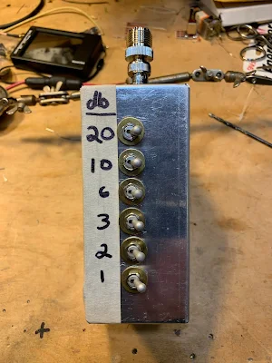
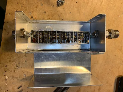
Fred, KC5RT, sent me an electronics "CARE Package" with lots of really useful stuff, including an attenuator with switches.  All I had to do was find a box and some connectors.  An appropriate box was quickly found in my junk box (TRGHS).  So Fred's attenuator was added to my attenuator arsenal -- thanks to Farhan for getting this started.  

I've already put Fred's attenuator to good use: Instead of building an RF gain control for my Q-31 receiver, I just put the attenuator between the antenna and the receiver.  

Thanks Fred!  


Tuesday, July 14, 2020

ON6UU's DB4020 EA3GCY Rig


Hi,

Recently I got the EA3GCY newsletter,  it announced a new kit DB4020,  a 2 band transceiver kit covering 40 and 20 mtrs.  I know Javier EA3GCY’s kit are good so I ordered one.  A week later it arrived in a brown enveloppe in which I found all components and printboard wrapped in bubblewrap,  it was all well packed and after checking all components all was accounted for,  all components were indeed there.

8 toroids have to be wound,  following the instructions it was piece of cake,  no problem,  

After several hours of work - relax max style - I got everything in place to test,  hurray,  no smoke !!!!  So now the SSB part was ready,  I have 7W on 40 and 3.5W on 20mtr.  Good power for qrp sota,  wff or just garden activity.  A fortnight later I got notice that the CW part of the kit was ready and another week later it arrived here,  I soldered the 2 boards as soon as possible to get a multimode 2 band transceiver.   The 2 boards are the CW interface which also holds the KB-2 keyer,  the second board is the 500-600HZ CW filter.   The KB-2 give the user 4 memories,  beacon function and some more functions.  Good thinking to include the keyer,  it makes life easy when you’re on an activation. 😊   I opted to make the filter switchable,  I like to be able to listen broadband too,  very simple,  cut one leg of the 13 pin connector on the bottom of the CW interface and put a switch on both ends.


After some figgling around I also got the box ready,  a military grade plastic box with wall thickness of 5 mm,  this box should be able to withstand a lot of shocks and a drop to the ground.  I also made a docking station for a laptop battery which holds some 5Ah and which should be able to give me a lot of hours of listening and some 2 to 3 hours of operation.  I had an old laptop which the screen was broken and had some other malfunctions,  I have taken the battery connector out of it,  luckily I still have another laptop which still works and this is the charging station for the batteries …. ..  😊   The docking is only to test,  I will box it up in maybe a some box where I can then maybe also fit a end fed solution or tuner for coax fed antennas.


A new radio also needs a new CW key so I made one out of an old relay,  painted the base green to fit somewhat the box et voila,  here is the result of the complete portable station.


The key can be fitted to the box by means of a bolt and a wingnut.  A short cable goes to the CW connector of the transceiver.

I had a lot of fun constructing this kit,  the box,  the docking and the key.   For 180€ you get a arduino nano controlled CW/SSB transceiver with 2 bands on which most of the activity is and you also get a keyer with memories.   Good deal I think.   More info is available on EA3GCY’s website.  Javier is also very quick in responding to questions,  he ask for opinions and offers almost an Elecraft style of service.

I made some video’s which are on youtube :

The kitters website :

Best 73
Frank
ON6UU


Monday, July 13, 2020

"The All Japanese 6" Receiver


One of the great things about having a "miscellaneous" box in an otherwise well-ordered junk collection is that rummaging through that box will often send you off on fun and interesting radio adventures.  I was rummaging yesterday and I came across the guts of the little AM radio that used to be mounted on my bicycle handle bars.  I last mentioned this in 2011 : 

I was just about to cannibalize this board.  The IF transformers were almost certainly at 455 kc and I could use a few of those.  But then I started thinking and Googling and trying to figure out the circuit.  That all led me this the site that provided the diagram below: 


Six transistors, four transformer cans, two audio transformers.  Yea, that's pretty close to what I was seeing on my board.  So of course I had to see if I could get it going.   I hooked up a 9V battery.  I connected the pot wiper connection directly to the connection at the top of where the pot had been (it had disintegrated).  It works!  It is inhaling nearby WFAX, Falls Church, Virginia. 

You will notice that the transistors in the circuit above are PNP.  I had assumed negative ground and had hooked the battery up accordingly.  No smoke was released and the thing worked, so I guessed that I had assumed NPN correctly.  Sure enough, perhaps aware of the PNP ancestry, the manufacturer had marked my board "BC123 NPN"! 

The author of the book I linked to above dubbed this circuit the "All Japanese 6"  -- an obvious allusion to the All American 5.  

I see real potential in these AJ6s.   A few mods to the front end and you could be shortwave listening, perhaps on 31 meters!   


BTW:  The space on my handlebars formerly occupied by that little AM radio is now taken up by a Bluetooth speaker that plays tunes streamed to my I-phone from Pandora as I make my way down the same old Washington and Old Dominion bike path.  Progress. 


Sunday, July 12, 2020

A Swedish Homebrew uBITX built in Dubai


It was great to get an update from Martin.  He has moved his workshop from Dubai back to Sweden.  We have seen lots of homebrew BITX monobanders, but very few homebrew multiband uBITXs.  Check out Martin's.  Very FB.   The input from Farhan was very cool, as was Martin's wise decision to follow Farhan's suggestion and to pause construction once the receiver was working.  As Martin put it, "I halted the build for a couple of days and just enjoyed listening."  Thanks for the update Martin. 


Dear Bill and Pete,

Here comes a long overdue update from my workbench, my last update was back in March 2017 when I had completed my first transceiver project.

I did not stop building and quite soon after I completed the CW transceiver Farhan posted the first schematics of the uBitx, why not? Why not get into a multiband CW-SSB transceiver as my next project.

After completing the receive part I was amazed... 


I halted the build for a couple of days and just enjoyed listening.
When it was time to start on the filters and the main RF Amp I sent Farhan an email asking about the way forward, he responded like this on May 17th 2017

"martin,
first, let me congratulate you, i suppose you are the first one to build a ubitx after me! second, i am not happy at all with the transmit line up, the drivers were not doing a good job above 14 mhz. i have replaced the 2n2219s with parallel 2n3904s. i also had to add two more LPFs, for proper harmonic suppression. i am headed for dayton today. once in dayton, i will try to find time to send you the latest circuit diagram. 
once again, congratulations on a wonderfully constructed ubitx."


Wow, what a shot in the arm for a fairly new home brewer!!! I was now back full speed with solder melting. I completed the filter bank and the RF amp, this is where I am starting to move away from the published diagram, I believe it is good to make it your own a little.

The end result was great, I worked many many stations in Europe and Asia with this little machine both SSB and CW.

In 2019 we decided to move back to Europe, the workbench and all boxes with parts and junk together with the rest of the household found their way into a 40ft container and was sent of to Sweden.

The A65DC Laboratories became SM0P Laboratories, the iron is still always hot and there is something brewing here all the time.

Thanks for a brilliant show boys,

Martin SM0P


Saturday, July 11, 2020

Q-31 Receiver Filter Fix with the NanoVNA


The picture above shows my problem. As predicted by the Murata data sheet and as warned by R.A. Penfold, that nice 455 kc ceramic filter has a significant response at around 640 kc.   This caused me to hear Brother Stair twice as often as I should have.  Clearly a spur exorcism was called for. 


Click on the picture for a better image.  As noted last time, my first idea was to build a series 640 kc trap LC circuit and put it ahead of the ceramic filter.  But I had trouble getting the desired high Q.  So I then thought about putting a wider 455 kc filter ahead of my 12 kc filter.  I would, of course, need one that did NOT have the 640 kc spur.  I found a 455B filter in my junk box.  I used the NanoVNA to look at its response.  No spur at 640 kc!  Yea!  


Next I put the two filters together, 455B first, then the 12 kc filter.  Success!  You can see on the NanoVNA that there is no spur at 640 kc. 

With close to the desired termination impedances, the passband at 455 kc looked pretty good.  I just put 1500 ohm resistors in series at the input and output of the dual filter combo. 

It worked.  Spur exorcised!  I no longer hear each SW broadcast stations at two spots on my dial.  

Friday, July 10, 2020

100 Years Ago: Hugo Gernsback on "An Amazing Art"

I like the art work in the header.  I like the reference to "the radio art."  I like that he refers in the first half of the piece to "the radio tribe" -- that would be us!  And this reminds me of "tribal knowledge."  He also talks about rigs "scattered across the table" -- Al Fresco!  

In the second half of the piece he veers off into a kind of weird call for standardization and ladies hats.   But the first half is good, and it is interesting to take a look at the hobby 100 years ago.  Click on the image for an easier read. 

Sunday, July 5, 2020

The Ceramic Spurs (not a rock group)


Paul Taylor VK3HN's magnificent AM receiver was the inspiration for my Quarantine-31 Shortwave Broadcast receiver.  Like Paul I decided to make use of ceramic filters at 455 kHz for selectivity.  I started with the +/- 3 kHz filters that Paul used, but I found them kind of narrow for SW listening.  So I went with some wider ceramic filters that Bruce KK0S had sent me.  But I misread the specs that Bruce sent.  I thought they were 10 kHz wide filters. I realized later that they were +/- 10 kHz -- really twice as wide as I needed.  So I went back to Mini-Kits in Australia and got some +/- 6 kHz filters.  12 kc wide should be just about right, I thought. 

The bandwidth was right, but I started noticing a problem:  I could hear strong SW broadcast stations at two places on my dial.  This brought to mind an admonition from R.A Penfold, author of "Short Wave Superhet Receiver Construction" (1991 Babani Publications).   He advised keeping a few standard 455 kc IF cans in the circuit because, he warned, the ceramic filters have spurious responses, spurs that the IF cans can help knock down.  

Penfold was right.  Look at the filter response curve on the right (above).  There is a nasty spur at around 640 kHz.   This was the cause of my problem. Here is why: 

Suppose I was tuning Radio Marti's big signal on 9805 kc.  My VFO would be running at 9350 kc. 
9805-9350=455.  Great, but... 
With that spur at 640 kc, I could tune down to 9620 kc on my dial.  My VFO would be running at 9165 kc. 
9805-9165=640.  Bad.   That 640 kc difference product would make it through to my detector and AF amp.  I'd have Radio Marti showing up in two places.  I didn't like this. 

I thought about putting a series LC circuit tuned to 640 kc at the output of the ceramic filter.  This looked like a possible solution, but on the bench it looked like I would have trouble getting a circuit of sufficiently high Q.  

So rummaging around in my junk box I found an old Murata CFM455B filter.  This filter is quite broad, but it does not have the spur at 640 kc.  I could use it as a kind of roofing filter just ahead of the +/- 6 kHz filter.  Putting it there would allow me to avoid having to build additional matching circuits for the 455B filter.  

+/-6kc filter upper left,  455B wide filter to the lover right. 

I'm happy to report that this fix works.   The 6 kc filter provides the needed selectivity, and the broader 455B filter knocks down the 640 kc spur. 

Beware the Ceramic Spurs!  

Q-31 with can for first IF amps and filters open


Tuesday, June 30, 2020

A Backyard Pandemic Field Day in France (Smoke Released!)


Thank you Alain! 

-------------

Hello Pete and Bill,

As you know I am a great fan of your blogs. The fields days are not usual here but because our both countries have been hard hit by the Covid I felt good to participate in this kind of (solo) activity.

My wife Patricia shot 2 pictures for you.

I did some QSO with my callsign followed by FD, but in my enthusiasm I pushed a bit the pressure on my small TX and the PA Mosfet went promptly to the sky...

As you will see, even my dog Guerlain (no callsign) participated...

Hope that you enjoyed a great FD.

Take care my friends.

73 Alain F4IET


Designer: Douglas Bowman | Dimodifikasi oleh Abdul Munir Original Posting Rounders 3 Column