Podcasting since 2005! Listen to Latest SolderSmoke

Sunday, October 11, 2020

Ryan Flowers' Admirable Approach to the BITX40 Module


We must remember that Farhan designed the BITX transceivers -- and especially the BITX40 Module -- in the hope that these rigs would encourage hams to tinker, to modify, to change and to repair.   When I read Ryan Flowers' blog post, I thought that Farhan's mission has been accomplished.  

https://miscdotgeek.com/bitx40-rebuild-part-1-mistakes-planning-and-teardown/

I was also struck by how nice it is that Ryan has a sentimental attachment to this BITX40 module because it was a gift from his wife.  That's the kind of thing that gives a piece of electronic circuity soul. 

Above we see Ryan's module with many of the parts removed in the sections that he feels he messed up.  This is obviously a good approach, but it reminded me of the nightmare I've had (and I am not the only one) where, in frustration, I take ALL the parts off a recalcitrant board.  

Stick with it Ryan!  You are on the right track.  And it sounds to me like you WILL soon be homebrewing from scratch your own SSB transceiver. 

A while back we built a blog with many nice mods for the BITX40 Module: 

http://bitxhacks.blogspot.com/


Saturday, October 10, 2020

Chip Replaced, GSC 6000 Counter Fixed


This thing has been half-broken for a long time.  I needed to get the input for 40 MHz - 650 MHz working    I got the a replacement SP8630B Plessey divide-by-ten counter chip on e-bay, and yesterday I extracted the old chip and put in the replacement.  I took great care NOT to solder this one in upside down (as I had done with another chip replacement in this counter). I used solder flux and solder wick to gradually get the pins free of the board. (You can see the old chip in the picture above.)

As to what happened to the original SP8630B chip,  John over on the Vintage Test Gear Facebook page wrote: 

The Plessey SP8630A/B is an ECL divide by 10 prescaler, with a upper working frequency of 600MHz. That generation went out of production in the late 1980s. Plessey was bought by a Canadian company now called Micrel. You may be able to find one from one of the specialist obsolete component companies, but it may be dead on arrival. Those ECL ICs had a fairly high mortality rate if they are very old.

It is the old story of "metal migration". In early semiconductors very small impurities in the silicon structure cause minute bits of the metallisation to leach out into the essentially non-conducting silicon insulation. Many old devices, although they have never been used, were found to be very leaky and this degrades the gain of the active devices. The worst types are the very old Germanium transistors.

As the semiconductor scientist learnt more about the super cleanliness required and the better purification of the metals the problem tended to improve. The Marconi company I worked for back in the 1980s had a real problem with comms satellites failing after a few years of service. Of course you can't go up there and swap out the faulty devices. Accelerated ageing of a backup satellite showed that some devices just stopped working after being subjected to high and low temperature cycling, which is a common problem with satellites in orbit!

I am liking this little machine more and more.  It is very simple -- no microcontroller, just a collection of gates.   I discovered that the main main crystal oscillator is actually built inside a little oven to keep the temperature stable -- oscillator and the oven stay on as long as the counter is plugged in, even when the device is switched off.  I calibrated the counter with WWV and with my HP8640B and with my little Feeltech sig gen counter.   I wish I knew how to calibrate the counter in the Rigol DS1102E oscilloscope.  


Friday, October 9, 2020

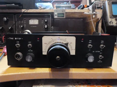
The Bitsy -- Homebrew Double Sideband from Scotland


This is such a beautiful project:  it involves DSB, homebrew, troubleshooting, George Dobbs, SSDRA, J310s, a box kite,  and ham radio nostalgia.  I was struck by how similar the Bitsy looks to some of my own DSB creations (but the Bitsy is nicer).  I'm really pleased to find a DSB project coming out of the UK -- when I was there, DSB was kind of frowned upon by spectrum preservation zealots.  I say there is plenty of room for the very few homebrew DSB rigs that will ever grace the airwaves with their presence.   Thanks John.  Have fun with all your projects.  73  Bill 

Hi Bill

In the early 80's I built and experimented with Direct Conversion Receivers and had a lot of fun with them. I came across a 40M DC cw transceiver by the late Rev. George Dobbs in a Practical Wireless magazine and decided to build it. Whether I was just lucky I'm not sure but it worked first time and I had several cw contacts with it. It was called “The PW Severn”. I then discovered DSB and looked into modifying the wee rig. I gave George a phone, no internet in those days, and explained what I was proposing to do and if there was any advice he could offer. His reply was ,  “it should work so try it and see, any problems get back to me”. It worked and I had a lot of fun with it. I used to take it portable and with a box kite to support a long wire and worked all over Europe.

It was after reading and learning about circuits and home brewing I wondered if I could design and build a DSB transceiver of my own. I had plenty of articles and most importantly a copy of Solid State Design, now well thumbed.

So the “Bitsy” was born. It is an 80M DSB transceiver. The PA produces about 2 watts. I took what I thought was the best for each module and built it using six circuit boards which I designed and etched myself. Nowadays I use the Manhattan method for one of circuits. It is much easier and quicker.

Like most home brew projects, the fun is in the building and the wee rig lived in a box for several years. Probably over 30. My doesn't time fly. I came across it again while looking through my boxes and decided to give it an airing. Expecting it to work on power up I was quite shocked when it produced nothing on both receive and transmit. After staring at it for a couple of minutes I unscrewed the lid and studied the wiring for a dry joint. Nothing so I switched on my Digital Multimeter and Oscilloscope. I soon found out that the output from the VFO was missing. The VFO uses one FET and two PNP Transistors for the buffers. The scope soon proved that the FET was faulty. I used an MPF102. These are hard to get so I replaced it with a J310. While I had the VFO out I also replaced the 9.1v zener diode, which provides a regulated voltage for the FET, with a 78L05 connecting the centre pin via a 580ohm resistor to earth. This gives me a 9.3v regulated supply for the oscillator. It is now back in full working condition.

With the Covid 19 epidemic I, like a lot of the Amateur Radio fraternity, am spending a lot of time in the shack and looking for new projects. I am buying back my old FT200 which was my first rig. An old friend and lapsed amateur has still got it and agreed to sell it back to me. It is still in a good condition for being nearly 50 years old and just needs some TLC. When it is finished it will take pride of place beside my restored Heathkit SB104A. And they say nostalgia is not what it used to be!!

John Forsyth

GM4OOU


Thursday, October 8, 2020

HA-600A Gets a New Coat of Paint -- After Almost 50 years!


The HA-600A that I picked up last week was looking kind of sorry.  There was a lot of rust on the cabinet.  Below is the before picture. 

I'm not really into cabinetry or radio aesthetics, but it is amazing what a 6 dollar can of spray paint can do. Formula 409 also helps. I moved the light bulbs forward a bit to get more light on that Juliano Blue dial. 

I am really enjoying this radio.  It has brought back many memories.  I think I got one for Christmas in 1972.  I was 14.  I got my Novice ticket on April 27, 1973 and made my first contact on July 19, 1973.  For that first contact I was using an HA-600A and a Heathkit DX-40.  Later I used the Lafayette with a Heathkit DX-100.   The HA-600A was replaced by the far superior Drake 2B on April 11, 1974.  So I used this receiver for more than two years.  

Looking around inside this receiver (and following up with Google) I learned some more about it: 
-- It was made in Japan. 
-- The manual says it has a "mechanical filter" but in fact it has a Toyo ceramic filter.  This may have been just an honest mistake by the folks who wrote the manual -- maybe they didn't understand the difference between the two types of filters. 
-- There is a big difference between the HA-600 and the HA-600A, mostly in the front end circuitry.  The HA-600 has fewer amplifier circuits at the front end.  This probably explains why the HA-600 I picked up did not seem to live up to my memories of my teen-year HA-600A.  

The fellow who gave it to me tells me that it had belonged to the short-wave listener father of a friend of his. 

I know we have a lot of tube-type receivers that are much older than this thing, but I still think it is pretty amazing that this is a receiver that I used almost half a century ago.  And it is still as good as new.

Wednesday, October 7, 2020

Solar Cycle 25 - The Gleissberg Cycle Dashes Hopes for a Big Solar Max


In our last podcast Pete N6QW expressed pessimism about Solar Cycle 25.   I pushed back, asking Pete to stop with the negative vibes.  Well, as always, it turns out that Pete was right. 

Hack-A-Day today has a nice post about solar activity.  They note that cycle 25 is likely to be much like cycle 24 -- not great, certainly not as great as cycle 19.  Pete operated during that magnificent event -- I was born during cycle 19 -- TRGHS.  

While Pete was right about the poor prospects for cycle 25, I doubt that he knew WHY it will be so tepid.  Well friends, here is something else for us to worry about:  THE GLEISSBERG CYCLE.  This one is not 11 years long.  It is 87 years long and we are in the declining phase right now. So apparently it will be future generations of ham radio operators who will experience sunspots like those of 1959.  Curse you Gleissberg cycle!  

But I suppose it is better to light one candle than to curse the darkness.   Cycle 25 maximum is only about five years away.  So I'm thinking of rebuilding my Moxon.   Or maybe getting a Hex beam... 

Tuesday, October 6, 2020

TRGHS -- My First SW Receiver Offered FREE for Pickup -- The Lafayette HA-600A (Looking for Globe VFO Deluxe)


So on September 27,2020,  I was sitting quietly in my shack, perusing the postings on various radio-related Facebook groups, when suddenly I saw it:  my very first shortwave receiver, the magic box that had put me firmly on the path to amateur radio, the Lafayette HA-600A.  Joe, the owner,  was offering it FREE to anyone willing to pick it up at his home in Virginia's Shenandoah Valley.  Holy Cow!  I was scheduled to drive through that very valley later that week.  A message was sent and the deal was done.  CLEARLY THE RADIO GODS HAD SPOKEN (TRGHS).  

Sure, the cabinet looked a bit rough, but I had high hopes for this receiver.  A while back I had -- in a similar fit of nostalgia -- bought what had been advertised as a Lafayette HA-600A on e-bay.  But it turned out to be a Lafayette HA-600 (no A).  I immediately noticed a big difference in performance.  That was NOT the radio that I remembered, not the receiver that had carried HCJB and Radio Moscow to me. Joe was clearly offering the A model.  

A few days later I was in Joe's front yard for the hand-off, and a few days after that the HA-600A was on my bench.  

I quickly realized how little I knew about this receiver.  Mine was a Christmas gift, probably in 1973. (A few days ago I talked to my mom and thanked her for driving all the way to New Jersey to get this receiver for me.)   I was so taken with this thing that I feared doing something -- anything -- that might mess it up.  I lived in fear, for example, that some sort of freak mid-winter lightning bolt might destroy it.  I covered it with a towel each night lest dust encumber its "jeweled movements." Obviously I was just not inclined to crack open the case and have a look around. So I didn't, and the receiver remained pretty much an appliance for all the time I owned it.  (I eventually sold it on consignment at Electronics 59 in Spring Valley, New York.  The proceeds probably went toward the purchase of a much better Drake 2-B receiver.) 

I downloaded the manual and familiarized myself with the receiver:  It is a single conversion superhet with a 455 kc IF.  It is all solid state with no ICs -- all discrete transistors and diodes. The manual claims it has a mechanical filter.  I kind of hoped for something like a Kokusai mechanical filter,  but it turns out that the filter was really ceramic, not mechanical.  Bummer.  

The thing fired up right away and was inhaling on the correct frequencies.  I noticed immediately that (as Joe had indicated) some of the controls were scratchy.  I also noticed that the ganged band selection switch was intermittent and required some jiggling to get it to work properly.  A few squirts of Deoxit D5 took care of all that. There seemed to be a bit of dirt in the main tuning capacitor, but I think I managed to blow that out using a can of Dust-off.    I was quickly listening to the SW broadcast stations, and to radio amateurs on 75 and 40 meters. 

Out of curiosity, I compared schematics of the HA-600 and the HA-600A.  There was indeed a big difference -- the front end of the 600 lacks a lot of the RFA amplification circuitry of the A model.  That's probably why is seemed so deaf and so different from what I remembered of the A model. 

There is really not a lot to do on this receiver.  I'll get some paint to fix up the top cover.  I may check the alignment.   But this single conversion receiver is so simple that alignment would be quite easy.  In many ways this receiver seems like a solid state analog to the Hammarlund HQ-100, but without the clock, and without the regeneration circuitry.   The dial lacks the exotic station locations (Java!) that make many of the older receivers so much fun.  I guess this is an indication that this receiver was aimed more at amateur radio operators than at shortwave listeners ( I was both).  I wonder how the ham band-only HA-800 compares to the HA-600A? 

I could pair this receiver up with a DX-40 transmitter that I have on the shelf and I'd be most of the way toward re-creating my novice station.  Anyone have a Globe VFO Deluxe?   That would complete the setup.  

Thanks very much to shortwave listener Joe Pechie for providing what is, for me, a very meaningful piece of gear. 

Here's a short video on the receiver: 
 

Sunday, September 27, 2020

A Suitcase Portable 40 Meter CW Station from 1951


Wow.  Check this out:

http://www.skywaves.ar88.net/homebrew/W9FKC.pdf

A very nice  rig built by an amazing homebrewer 

And thanks to Al Klase N3FRQ for putting that wonderful web site together. 

Thursday, September 24, 2020

Global Specialties Corporation 6000 Frequency Counter -- Anyone have a Plessey SP8630B Chip?


Continuing my effort to improve my workbench and its test gear, this week I turned to an old frequency counter that I picked up at the Kempton Park Radio Rally in London many years ago. It was not working when I got it, but long-time SolderSmoke listeners will recall the tale of woe that resulted from my having soldered a replacement IC (that Tony Fishpool G4WIF had sent me) UPSIDE down.  Tough times my friends,  tough times. 

Well,  I'm working on it again.  First I converted it from 220 to 110 power.  I had a transformer in the junk box that fit nicely, both electrically and mechanically.  In the course of doing this, I learned something about this counter that I did not know:   As long as it is plugged in, even if you turn it off, the time-base oscillator keeps running.  And get this Color Burst Liberation Army members:  The oscillator runs at 3.579545 MHz.  TRGHS.    

With sunspots scarce and with Pete pessimistic about the solar cycle, VHF and UHF now seem more interesting.  I need to have more test gear for the higher frequencies.  This counter works up to 650 MHz.  Yea! 

When I first fixed this thing, I was quite pleased to get it going with "Input A -- 5 Hz to 100 MHz."  But now I want to get "Input B -- 40 MHz to 650 MHz" working also. I used a 50 MHz signal from my newly repaired HP-8640B to trouble shoot Input B.  I think one of the divider chips is bad.  It is a Plessey SP 8630B.   Does anyone have one of these chips in their junk box?  


Wednesday, September 23, 2020

Wisdom from AA0ZZ: NO LIBRARIES! ASSEMBLER CODE ONLY! -- "Digital Crap" -- "No Magic Fruit" What qualifies as a real rig? Si570 vs. Si5351


Bill,

Why do you guys make your Soldersmoke podcasts so darn intriguing such that I can’t listen to them in the background while I’m doing something else?   Good grief!  I start listening and before long you make me stop and chase down a rabbit hole to find something new that you mentioned that I had no clue was out there.    Before long I’m doodling out a new sketch or playing with at a new design for something I really need to experiment with or build “next” or something I need to  try.   It is taking too much of my time!!  J

 I’ve been listening to your podcasts for years.   Way back, before I knew you and before I knew you were doing these Soldersmoke blogs with Mike, KL7R, and just before he was so tragically killed, I was collaborating with him on a simple frequency counter project using a PIC microcontroller.  We were making good progress on a neat design.  I later completed the project but always kept his contributions noted as part of the source code. 

 I’ve been making PIC-based VFOs for years – dating back to about 2000 – aiming them at builders who were looking for something to go along with Rick Campbell’s (KK7B) receivers.  Rick is a good friend now, after we met in the Kanga booth at Dayton where we both were demonstrating our stuff.  (Bill Kelsey (N8ET) of Kanga, was the “marketer” for my kits as well as Rick’s for many years.)   My original VFO kits used a DDS (high-end AD9854) that simultaneously  produced I and Q signals which made it perfect for Rick’s phasing gear.  Rick is a big supporter of my work but he still kids me about polluting his beautiful analog world with my “digital crap” (copyright KK7B term).   When I came out with a newer version VFO using a Silicon Labs Si570 PPLL  (I can hear already Pete Juliano groaning) it was a big improvement over the AD9854 in noise/spur reduction.  I documented this all in a QEX article in about 2011 and Rick (and Wes Hayward) were very supportive/appreciative of my work.   

 I have used the Si5351 also and I understand Pete’s point of view.  It’s “plenty good” for most amateur projects.  However, it remains a fact that the Si570 is a better part and produces a cleaner signal.  That’s the reason why the Elecraft KX3 uses a Si570.   Granted, the newer Elecraft KX2 uses a Si5351 but it’s most likely because they wanted to preserve battery life (the Si570 uses more power but not nearly as much as the AD9854) and also to reduce the cost.   I do understand!   I also fully understand the ability of the Si5351 to produce I and Q signals via different channels.  I’ve had extensive conversations about this with Hans Summers, at Dayton and online.  I use a pair of Flip-Flops on the output of the Si570 instead.  My PIC code driving the Si570 is ALL written in ASSEMBLER code.  Yep!   I’m an EE but have had a career mainly in software development and much of it was writing assembler code.   I dare say there aren’t too many gluttons for punishment that do it this way.  I do it because I want to understand every line of code don’t want to be dependent on anyone else’s libraries.  Every line of code in my VFO’s and Signal Generators is MINE so I know I can debug it and it can’t get changed out from under me.   (This problem bit Ashar Farhan hard on the Raduino of his BitX.   Tuning clicks appeared because the Si5351 libraries he used changed between the time he tested it and released it.   I was really appalled when I dug into this and resolved to NEVER use libraries that I didn’t write myself.  Similarly, this also makes me have some distaste for Arduino sketches.  I would rather see ALL of the code including the initialization code, the serial routines, etc, rather than having them hidden and get pulled in from Arduino libraries.  That’s similar to the reason why Hans Summers didn’t use an Arduino in his QCX.  He used the same Atmel microprocessor but developed/debugged it as “C” code with the full Atmel IDE/debugger.                                                                                                            

By the way, Pete  mentioned the Phaser FT8 transceiver by Dave, K1SWL, in a recent podcast.  Dave is a very close friend, even though I haven’t met him in person since about 2000.  We Email at least daily and some of it is even about radio. J   I did the PIC code for the tiny PIC that controls the Si5351 in the Phaser.   Yes, it’s written entirely in Assembler again!   I do know how to do it for a Si5351.  That Si5351 code is not nearly as much “fun”, though.  I know, this will make very little difference to guys who write Arduino “C” code to control it but under the covers it’s a world of difference.   It takes me about 15 serial, sequential, math operations to generate the parameters for the Si5351.  None of them can be table driven and they all have to be performed sequentially.   (This is all hidden in about 5 lines of complex, Arduino “C” code but the operations are all there in the compiled assembler code.)   In contrast, my Si570 code is almost all table driven.   I just have to do one large (48-bit) division operation at the end to generate the parameters.    Yes, that’s a bit of trickery to do in ASM.   There are no libraries do this.

 I will point out one more advantage of the Si570 in comparison to the Si5351.  It has the ability to self-calibrate via software instead of relying on an external frequency standard.  In my Si570 app I can read up the exact parameters for the crystal embedded inside the Si570, run my frequency-generating algorithm “backwards” and determine the exact crystal frequency (within tolerances, of course) for that particular Si570.  Then I update all the internal tables using that crystal frequency and from then on all generated frequencies are “exact”.   I love this!  Frequency often moves by about 6 kHz on 40M.

 Oh yes, I must mention the difference of home solderability of the si570 vs the Si5351.  Those little Si5351 buggers are terribly difficult to solder at home while the Si570 is a breeze.   I know, many folks will just buy the AdaFruit Si5351 board and it’s already soldered on but, again, I like to do it all myself.   No “magic Fruit” for me.

 Now that I retired a couple of years ago and am getting out of the VFO kitting business I can finally build complete rigs instead of just making the next-generation VFO’s for everyone else to use.   I recently build a tiny, Direct Conversion rig with a Si570 signal generator (of course) and a diode ring mixer (ADE-1).  Look at my web page,  www.aa0zz.com  to see it, along with my VFO projects that I’ve been building in the past.   As you well know, Direct Conversion is fun to build and the sound is astounding; however, they are rather a pain to use!  Yes, I did make it qualify as a real rig by making several contacts all over the country.  (Wes Hayward gave me the criteria:  he told me that I must put any new rig on the air and make at least one contact before it qualifies as a real rig.)  

 The new rig that’s on my workbench is my own version of a phasing rig, experimenting with a Quadrature Sampling Detector (QSD, sometimes called a “Tayloe” mixer), using some ideas from Rick’s R2 and R2Pro receivers and many innovations of my own.  At present my new higher-end Signal Generator works great, the QSD receiver works great (extremely quiet and MDS of -130 dB on 40 meters) and the transmitter is putting out about 16 watts with two RD16HHF1’s in push-pull.  You can take away my “QRP-Only-Forever” badge too, not that I’ve ever subscribed to that concept!  Still more tweaking to do with the TX but now I’m also working on the “glue” circuitry and the T/R switch.   The SigGen, RX and TX are all on separate boards that plug into a base board which has the interconnections between boards and the jacks on the back.  I’ve built DOZENS of variations of each of these boards. Fortunately they all fall within the size limit criteria to get them from China at the incredible price of $5 for 10 boards (plus $18 shipping) with about 1 week turnaround.   Cost isn’t really an object at this point but it’s more of getting a hardware education that I sadly missed while I concentrated on software for so many years.  it’s certainly nice to have willing mentors such as Rick, Wes, Dave (K1SWL), Don (W6JL) and many others to bounce my crazy ideas off.  Yes, I’m having a ball!  

 I was licensed in 1964 but out of radio completely from 1975 to 1995.   Do you like the picture of my DX-100 on my web page?  My buddy in the 60’s had a Drake 2B and I drooled over it but couldn’t afford one.

Now I must finish this rig before you guys send me down another rabbit hole.   Too many fascinating things to think about!   I literally have a “priority list” on the my computer’s desktop screen.  Every time I come up with a new project idea – something I really want to play with such as a Raspberry Pi, SDR, etc, I pull out the priority list and decide where it fits and what I want to slide down to accommodate it.  That’s my reality check!

 Take care, Bill.   Thanks for taking the time to give us many inspiring thoughts and ideas.

 73,

-Craig, AA0ZZ

Monday, September 21, 2020

HP8640B Internal Frequency Counter Fixed (More Repairs Pending)


The HP8640B is a complicated machine.  Above you see just one sub-assembly, and the page from the manual that describes it.  This is what I've been working on.  The little spring "tine" fell out of one of those discs behind the two control knobs.  So I had to open this thing up, find the spot from which the tine had fallen, and glue it back in.   

I used Gorilla Super Glue, followed 24 hours later by a dab of JB Weld "minute weld" dual epoxy. One of the other tines was about to fall out, so I went ahead and gave all the tines in this assembly the glue treatment.  ( I bought some "Weld On" acrylic cement but the warnings on the label were quite sobering.  So I left that can sealed up.) 

This morning I put the thing back together.  This is not easy.  At one point a spring popped and a tiny metal part that is probably irreplaceable seemed to fly away into the black hole that is the shack's carpet.   I had just about given up hope when I found the thing sitting right in front of me on the bench.  TRGHS. 

The HP8640B fired up right away without trouble and the internal frequency counter is working fine. 

As I noted in the last SolderSmoke podcast, a very nice community devoted to the HP8640B has developed around the world.  Here are some of the notable participants: 

Bill at Electronics Revisited is a very nice fellow with lots of experience on the HP8640B.  He offered to sell me a replacement unit for the assembly pictured above.  If you have an ailing HP8640B and are looking for someone to work on it for you, Bill is the guy you should talk to:  http://www.electronicsrevisited.com/  He also very kindly offers to answer any questions you may have about the HP8640B. 

Here is the e-bay page of the fellow in Bangalore who makes the brass gears.  Mine are on the way! 

Marcus VE7CA has a great site devoted to the HP8640B: https://www.ve7ca.net/TstH86.htm

BH1RBG in China has a nice site describing his adventures with the HP8640B: https://sites.google.com/site/linuxdigitallab/home/hp8640b-20v-power-supply-down

K6JCA has a good blog post about fixing the tines and the gears: 

Steve Silverman (who gave me this HP8640B) found a really useful  history of the device: 

And of course special thanks to Dave VE3EAC who alerted me to the falling tine problem and put me on the path to a successful repair.  

The gears should be here in a few weeks, so that will be another opportunity to work on this HP8640B.  Also there are some tines in the attenuator assemby that might reinforce with the glue treatment. 

Saturday, September 19, 2020

SolderSmoke Podcast #225: Mars, uSDX, G-QRP, HP8640B, DX-390, Rotary Tools, Walla Walla SDR, MAILBAG

SolderSmoke Podcast #225 is available

http://soldersmoke.com/soldersmoke225.mp3

Mars,  West Coast smoke.

Pete's Activities: 
-- DC receivers.
-- CW offset
-- GQRP talk
-- The uSDX project

Bill's Bench
-- Sliding into the Vintage Test Gear Cult:  HP8640B . 
-- Fixing up and figuring out Radio Shack DX-390 receivers.  
-- 220 to 110 on a few remaining devices.     
-- Got myself a Dremel-like rotary device.  

Tech News: 
-- ARRL/TAPR Convention:  SDR project from Walla Walla University students.   Intuitive explanation for why desired and image freqs in a mixer come out with very useful phase differences.  

-- Chuck Adams' Amazing Lab Notebook.   Includes a simple circuit to measure resistance and Q in crystals.  FB. 

MAILBAG: 

-- Dino KL0S  SITSing in his shack, homebrewing 9 MHz filters  FB Dino.  Airborne! 
-- Dave NT1U sent us the famous 1968 QST Article by W7ZOI re DC RX.  
-- Ron K0EIA listening to SWBC staions with uBITX.  
-- Ted AJ8T  Korguntubes making a 12AX7 equivalent.  
-- Joel N6ALT sent me a nice DX-390 manual.  Thanks Joel
-- Bob KD8CGH alerted us to the uSDX project -- story on the blog. 
-- Craig AA0ZZ Sent a great message with insights on computer code -- I will put up on the blog. 
--Tracy KN4FHX reports on optimistic prognosis for SolarCycle 25.  Some chickens may have to be sacrificed.   
-- Stephen M0OMO Thanks SolderSmoke for rekindling interest in this hobby. 
-- Paul VK3HN  has a cool new rig -- The Prowler -- check it out
-- Steve N8NM working on his Sunbeam car -- Pete already knew about the carburetor synch problem.  N6QW knows everything. 


Friday, September 18, 2020

Mixer Insights using Propellers and Cameras -- From Walla Walla University. And SDR Design Info.

 
Pete Eaton sent us this video from the 2020 ARRL/TAPR Communications Conference.   I have the portion of interest cued up (above).  (The portion of interest begins at 6:59:46.)

There is a lot of really cool SDR design info in this video and in the associated paper  (the TAPR site says you have to pay the ARRL $9 for the paper, but in the comments someone says the papers will be available free after the conference).  

What caught my attention was the students' discussion of mixer action.   They use an analogy with a spinning propeller (the incoming RF) and a camera (triggered by the local oscillator) that samples the incoming signal at a specific rate. This is analogous to a Quadrature Sampling Detector. 

The really interesting part for me was how this analogy allows us to see how phase differences between the desired signal and the image signal arise.   These phase differences permit an SDR receiver (or indeed an old fashioned phasing Direct Conversion receiver) to reject the image while allowing the desired signal to pass.  

This is a key point in understanding mixers, and is really quite amazing. Before I saw this video, I had just come to accept (without understanding WHY) that the desired signal and the image signal would have phase differences, EVEN IF THEY WERE COMING OUT OF THE MIXER AT THE SAME FREQUENCY.  It is this phase difference that allows us to knock one down while allowing the other to pass. The propellers and cameras of Walla Walla University gave me insight as to how and why these phase differences exist.  

In their paper, the Walla Wall group mention uSDX, the project that is currently generating so much excitement around the world: 

Low-cost is not the only reason SDRs have become more popular among the amateur radio
community. More recently, Guido Ten Dolle’s μSDX open source transceiver has generated
increasing interest in quadrature sampling down-conversion SDRs in the homebrew QRP
community. Guido, PE1NNZ, was able to modify the QCX, QRP transceiver for SSB operation
with an efficient class-E amplifier, using only an ATMEGA328 and Arduino code to run the QSD
SDR. This groundbreaking work in this type of SDR has inspired various renditions of Guido’s
radio, fostering a lively groups.io group that can be followed at https://groups.io/g/ucx.

Kudos to Caleb Froelich, Dr. Rob Frohne KL7NA,  Konrad McClure, Joshua Silver, and 
Jordyn Watkins KN6FFS,  all of Walla Walla University,  for some really impressive work.  (BTW:  Rob tells me that back in the mid-90s he too built one of Rick Campbell's phasing receivers and wrote a QST article about it  (probably the first SDR article published by QST).  Details on the project are here: http://fweb.wallawalla.edu/~frohro/R2_DSP/R2-DSP.html

Designer: Douglas Bowman | Dimodifikasi oleh Abdul Munir Original Posting Rounders 3 Column