Podcasting since 2005! Listen to Latest SolderSmoke

Friday, November 5, 2021

The Importance of Keeping the Noise FLAT


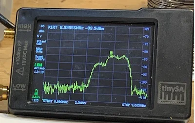
A few days ago I put up a blog post about using a noise generator (in my case my cheap FeelTech sig generator) and my TinySA spectrum analyzer to look at the passband of a crystal filter.  I was using the 9 MHz filter used by Dean KK4DAS and the Vienna Wireless Makers Group.  The idea is simple: insert broadband noise into the input. The filter should pass more of the noise that falls within its passband.  The TinySA should let you see this.  At first, I was pleased that I could clearly see the passband.   I thought I had succeeded.  See above. 

But I was bothered by something.  Look at that bump in the passband.  It should be close to flat across the top.  

I decided to take a look at the same filter with my NanoVNA.  Here I was not using a noise generator.  The NanoVNA sweeps the filter using and looks at output in the Log-Mag mode.  Here is what it looked like (below): 


That was much better.  But why the difference?   Tony Fishpool G4WIF suggested that my noise source might not be putting out noise at the same level on all frequencies.  I took at look at the noise output of the FeelTech sig gen in the range of the filter passband (with some above and below frequencies for reference) and I found that the flatness of this noise depended a lot on what frequency I had the sig gen set to.  I tuned it around a bit until I found a setting that produced a flat noise output in the desired frequency range.  Then I went back and swept the filter with the noise and the TinySA again.  Here is what it looked like with the "flat" noise: 


Better,  I think.  Closer to the passband displayed by the NanoVNA.   

Tony points out that these Chinese sig gens don't really put out random noise -- they give us predictable noise.  Dean said "Predictable Noise" would be a good name for a rock group.   I said they could open for my favorite: "The Ceramic Spurs." 

Tuesday, November 2, 2021

Farhan's Amazing Knack Story: From a Boyhood SW Receiver to the Design of the sBITX SDR


The presentation starts at about the 4 minute point. 

I think if I were only allowed to watch one YouTube video in the next year, I'd make it this one. 

In this amazing RSGB video, Ashhar Farhan VU2ESE takes us back to his earliest days as a radio amateur.  He tells us about his very early desire to build radios, his early projects, and his personal evolution as a designer and builder,  from a simple DC receiver, to the BITX, the Minima, the uBITX and now the hybrid HDR/SDR sBITX.  

There is a lot of  homebrew wisdom and tribal knowledge in this video. And we learn so many hitherto unknown details about the rigs that have become so important to us:  

-- Farhan had the EMRFD book with him on the famous flight from Sweden to India during which the BITX was designed. 

-- We learn about the origins of the BITX oscillator circuits, and that the VFO and BFO are essentially the same.  

-- I was really pleased that Farhan included a picture of my HB BITX17 rig in his presentation. 

-- Farhan discusses the difficulties he faced in obtaining needed parts in India. 

-- We actually see the nylon washers that Farhan used in the original BITX. 

-- Farhan discusses his early system for measuring coil inductance. 

-- In addition the huge contribution of EMRFD,  Farhan talks about how he was helped by Pat Hawker G3VA's writing, and the ARRL's SSB Handbook. 

-- Farhkan talks about his Tex 465 'scope and his building of a Spectrum Analyzer. 

-- We see his evolution to dual conversion. We see the conceptual birth of the Minima and the birth (thanks Wes!) of the TIA amps.  I didn't know about the HF-1.  Then Farhan designed the uBITX and now the sBITX.  

 -- Farhan talks about his practice of taking the pictures of new rigs with the new rig sitting atop the book that was most important in its design and construction.  FB. 

-- I was really blown away by Farhan's presentation of how the uBITX advertisement was inspired by and in many ways based on the Heathkit ad for an HW-101.  Amazing. 

-- I learned a lot from Farhan's discussion of SDR theory.  I pledge to spend more time with this.  I really like Farhan's hybrid HDR/SDR approach. 

-- But I have a question:  Farhan seems to say that we'd need a big expensive GOOGL computer to do the direct sampling HF SDR.  But doesn't the little RTL-SDR do just that?  Without a GOOGL?  

-- Great to see Wes's AFTIA being used in the sBITX.  

-- Really cool that Farhan has his mind on VHF transverters when designing the sBITX.   I liked use of the TCXO module to free up one of the Si5351 clock outputs.   FB.  And great to include an idea from Hans in this rig. 

Thanks very much to Farhan (who stayed up until 3 am to do this!) and to the RSGB for hosting.

Sunday, October 31, 2021

Buy a Real Sputnik Satellite! Let's Put Sputnik Back in Orbit!

Only 85,000 Euros (that's the opening bid).  But hey, it comes with the receiver pictured on the right.  I guess that's so you can listen to the beeps. 

Here's the description: 

---------------

Laboratory Test Model of "Sputnik 1 EMC/EMI", 1957
1:1 scale test model of the satellite "Sputnik-1", serial no. "0K6-1/004/1957", with built-in transmitter (including modern 12-volt power supply), polished stainless-steel sphere, consisting of two threaded hemispheres of approx. 23 in. diameter with two pairs of antennae of 95 in. and 105 in. at an angle of 35 degrees to the axis, on stand with O-ring, stand approx. 59 in. high, stand and model together approx. 79 in. high, accompanied by a Tesla Maj 620A radio receiver, manufactured in Prague c. 1956, restored working condition, including replacement of the silver-zinc battery with a modern alternative and a new metal casing for the electronic transmitter. Note: Built at the Experimental Design Bureau-1 (OK?-1/OKB-1) factory, also known as S.P. Korolev Rocket and Space Corporation Energia, Koroljow, Soviet Union, in 1957, shortly before the launch of Sputnik-1. - An impressive artefact from the dawn of the space age, of which few models are known. - Provenance: From the collection of Dr. Frank Malina, USA/CSSR.

Start Price: EUR 85.000

---------------------------

I'm a bit suspicious of the "modern 12-volt power supply,"  the "modern alternative" battery and the "new metal casing for the electronic transmitter."

Here's the link to the auction: 

https://www.the-saleroom.com/en-gb/auction-catalogues/auction-team-breker/catalogue-id-breker10030/lot-9c87007d-f0ff-4414-9663-adc200690819

Here's my suggestion:  Musk or Bezos or Branson should buy this thing, fix it up a bit, and put it back in orbit.  So we can listen to it again. I know a version of this was done back in 1997.  But I think we should do it again, this time with the actual test model. 

Here are the earlier SolderSmoke blog posts about Sputnik and Sputnik-related projects: 

https://soldersmoke.blogspot.com/search?q=Sputnik

Steve Silverman sent the auction posting to me.  Thanks Steve. 

It just so happens that earlier in the week I was out at the Air and Space Museum facility near Dulles Airport, where I saw this flight backup of the Vanguard satellite: 

Saturday, October 30, 2021

Using Noise to Sweep a Filter with the TinySA

 
I've been meaning to try this for a long time.  Years ago Tony Fishpool and Graham Firth wrote about using a noise generator and a spectrum analyzer to sweep the bandpass of a filter. The idea here is to send very broadband noise into a filter, and then use a spectrum analyzer to see which frequencies make it through.   

I thought about building a noise generator like the one in Tony and Graham's book, but then it occurred to me that probably had one sitting on my bench.  Sure enough, a look at the manual for my cheap FeelTech function generator revealed that PRESETS 3 and 8 are noise generators.   I quickly pulled out a 9 MHz filter that Dean KK4DAS had given me, put the noise into one end and the TinySA on the other end.  Bob was quickly my uncle.  See above.  

More recently Tony G4WIF built a comb generator as a noise source: 

Thanks to Tony, Graham, and Dean.  And to the folks who developed the TinySA. 

Wednesday, October 27, 2021

Why Does Solder Smoke Always Go Right Into Your Face? Now We Know


Because our podcast and blog is called SolderSmoke, I felt compelled to post about this video in which a fellow does some pretty interesting research into how solder smoke actually moves.  We don't often see this much concern about the behavior of our beloved smoke. 

Thanks to Todd K7TFC for alerting us to this.  

I use a small fan to disturb the airflow pattern. 

How to Listen with your TinySA


We don't get many chances to do hardware work on a piece of gear like the TinySA, but here we have one.  I mentioned this a while back:  Not only will the TinySA display the signals it detects, but it will also allow us to listen to these signals.  Very cool.  I am going to do this.  

Here is the link showing how to do the mod: 


All the cool people listen to classic rock with a TinySA: 

Tuesday, October 26, 2021

SETI, Proxima Centauri, The Parkes Dish, and Intermodulation Distortion?


https://www.sciencealert.com/exciting-mystery-space-technosignals-were-indeed-produced-by-sentient-life-us

A cosmically interesting troubleshoot.  But I'm not sure about their explanation.  Why would the intermod disappear when they moved the Parkes Radio Telescope off of Proxima Centauri?  


Monday, October 25, 2021

Putting a Ceramic Filter in the "Mate for the Mighty Midget" Receiver


It is really simple.  I had one of the +/- 3kHz (6 kHz wide) 455HT filters on hand.  The spec sheets call for 2000 ohms at both ends, but looking at the schematic it appeared that I already had high impedance on both sides of the filter.  I put a .001 uF cap on the input side to keep the DC voltage off the filter (see above and below). This capacitor allows us to avoid the dreaded problem of electro-migration that is so nicely described by SV8YM here: 


Tasos also provides a good description of the innards of those little black boxes that contain ceramic filters. 

Once you get the filter in your receiver, you have to carefully place the BFO signal in relation to the filter passband.  I have trouble properly sweeping 455 kHz filters -- my HP8640B will not go that low.  Nor will my Antuino (I need to modify the code -- someone help me please).  I know the NanoVNA will do the job, but I just couldn't seem to get it to work.  So I went "old-school" and manually swept the filter using my FeelTech sig gen and my Rigol scope.  This gave me a rough idea of where the passband was.  I put the BFO on the low end of the filter passband, at 451 kHz.

   
With this filter the MMM RX has become a real asset.   The 6 kHz bandwidth allows for nice reception of both SSB signals and AM sigs.   I may try to use one of the +/- 2 kHz filters  (4 KHz wide), but so far I have not been able to find a source for this part. 

Sunday, October 24, 2021

WA9WFA's Mate for the Mighty Midget 1966 QST Receiver

Scott WA9WFA and I have been exchanging e-mails about his Mate for the Mighty Midget receiver project.  This morning I finally took a look at Scott's we page on this effort.  There was a lot there that resonated.  For example: 

"I remember the moment very clearly.  June 1966 I was sitting in a lawn chair reading a stack of QST's that I had brought along to the summer cabin.  The February 1966 issue the Beginner and Novice section introduced the "Mighty Midget Transmitter", a 10 watt crystal controlled transmitter.  The April 1966 issue Beginner and Novice section introduced the "Mate for the Mighty Midget" which was a three tube super-heterodyne Novice type receiver.  Over the course of that summer I read and re-read those articles a jillion times.  Being 13 years old, I didn't have the electrical or mechanical skills to pull off such a project so I could only dream about it.  In 1970 I bought a handful of the parts.  In 1976 I bought more parts.  In 2021 I decided to build it while I still had the ability to do it.  This project is only my second homebrew radio project so I am still learning things every second of the way...
 
While I am not expecting to much in performance, the 13 year old in me is ever hopeful that this 1966 Novice receiver will be the most wonderful radio ever made.   73, Scott WA9WFA"

Scott's MMM RX page: 

Scott and I are now both updating the MMM RX by substituting 455 kHz ceramic filters for Lew McCoy's FT-241 crystal filter.   I have my filter wired in now, and it is working well.  Scott plans on soldering his in today.  I will post on this mod soon. 

On his QRZ.com page, Scott notes the need to fight the temptation to further soup-up this simple receiver:  "I did have to resist the temptation to add another audio stage, a mechanical filter, AGC, 2nd IF amplifer stage, etc..."

Exactly right Scott.  Resist the temptation.   Simplicity is a virtue.  I do use an outboard, powered computer speaker, but I justify this by telling myself that I just don't want to use headphones.  But I could use headphones, so this is OK.  OK?  

Scott's QRZ.com page: 

I must add that I think the yearning of Scott's inner 13 year-old can be fulfilled by the MMM RX.  I think it is pretty wonderful.  It is -- in my view  -- not as good as a Drake 2-B, but it is FAR better than an S-38E, and it is better than a Lafayette HA-600A (wjm).  

Friday, October 22, 2021

Tribal Knowledge: Pete N6QW on "How to Make Things Work"

 
BUILD IT LIKE THIS

Yesterday Pete Juliano published a blog post that contains an enormous amount of tribal knowledge and good advice for homebrewers.   As I read Pete's post, I thought back on my own failed teenage efforts at homebrewing -- the Herring Aid Five fiasco came to mind.  I also thought of Farhan's comments about his similar frustrations with early homebrewing efforts (though I find it hard to believe that Farhan EVER had trouble making something work). 

Above we see a large N6QW prototype breadboard.  Note how it is easy to see where the various stages start and stop.  This is key to understanding and troubleshooting a complex rig.   If you want to see the antithesis of this approach, here it is:

DO NOT BUILD IT LIKE THIS

This was supposed to be an 80 meter DSB transceiver.   The builder (who will remain anonymous) obviously didn't get it to work.  I think he should try again, using Pete's methodical approach. 

Check out Pete's great advice here: 


Thanks Pete! 

Wednesday, October 20, 2021

Super-Regeneration is Super-Strange


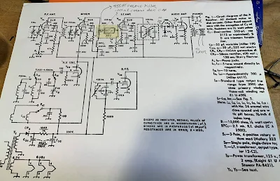
Farhan VU2ESE is largely responsible for this.  He has recently been talking about VHF.  (More about this in due course.).  This started me thinking about my failed effort in London to get on 2 meter AM.   My plan was to use the transmit portion of this HW-30 (above) with a 2-to-10 downconverter and my trusty Drake 2-B for receive.  

Tony G4WIF also bears some responsibility:  When I expressed interest in Farhan's VHF work, Tony sent me two articles from SPRAT.  Both of them were about super-regenerative receivers.  

Farhan's comments caused me to pull the HW-30 out of storage.  I started poking around the transmitter.  But then I noticed something:  On receive, the AF amplifier was obviously working.  Then, when I tuned through the 2 meter band, the rest of the receiver seemed to be working too.  I fired up the HP-8640B sig gen on 2 meters and turned on the AM modulation.  Indeed, the old receiver was inhaling!  

This launched me into an effort to understand how super-regenerative receivers work.  There are a lot of really weak explanations out there. You get the distinct impression that the person explaining the circuit does not understand it himself.  This makes explaining it very difficult.  I am not the only one to notice this phenomenon:  Mike WU2D commented on this in one of his excellent super-regen videos.  This one:  


Mike very kindly said the operation of this circuit seems like "magic."  I was thinking more in terms of Voodoo.  

Howard Armstrong discovered super-regeneration years after he invented plain old regeneration.  The new discovery came around 1921.

It looks like VHF guru Frank Jones had very early misgivings about super-regeneration.  In his 1934 classic 5 Meter Radio Telephony, Jones seems unenthusiastic about the circuit and about our ability to understand it:  "To explain, simply, exactly how this form of detection takes place is not a simple matter, but some of its characteristics are easy to visualize."  In this book, Jones goes on to predict that super-regens will be superseded (!) by superhets.  Indeed, in his 1961 book VHF for the Radio Amateur there are no super-regen circuits; all the receive systems are down-converters to HF receivers. 

Still, with that HW-30 hissing away right next to me, I feel I need to understand how the super-regen works.  I'm not there yet, but I'm trying.  Here are some good resources: 

A good article from Wireless World 1946:  

A student's write up of his effort to understand: 

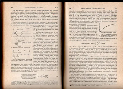
But the best so far (for me) is from Frederick Terman (one of the founders of Silicon Valley) in  his 1943 classic Radio Engineer's Handbook.  Click on the images for a clearer view. 


I will definitely try to get the HW-30's 5 watt AM transmitter going.  I am not so sure I'll do anything with the receiver.  I think this is a matter of picking your battles and "finding joy."   I didn't find joy in FT-8, so I stopped working with it.  Same with my HA-600A, DX-40 Novice rig.  Same with CW in general.  And the same with SDR.  I suspect that super-regen receivers may also fall into this category.  I mean, let's face it, if you are not fond of ordinary regens, is there any real chance that you will like SUPER-regens?  Even Frank Jones seems to have disliked them.  And there is a reason Howard Armstrong moved on to superhets -- they are better! But still, that receiver is hissing away at me...  Stay tuned. 

Designer: Douglas Bowman | Dimodifikasi oleh Abdul Munir Original Posting Rounders 3 Column