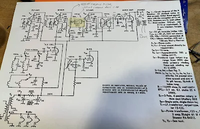
It is really simple. I had one of the +/- 3kHz (6 kHz wide) 455HT filters on hand. The spec sheets call for 2000 ohms at both ends, but looking at the schematic it appeared that I already had high impedance on both sides of the filter. I put a .001 uF cap on the input side to keep the DC voltage off the filter (see above and below). This capacitor allows us to avoid the dreaded problem of electro-migration that is so nicely described by SV8YM here:
Tasos also provides a good description of the innards of those little black boxes that contain ceramic filters.
Once you get the filter in your receiver, you have to carefully place the BFO signal in relation to the filter passband. I have trouble properly sweeping 455 kHz filters -- my HP8640B will not go that low. Nor will my Antuino (I need to modify the code -- someone help me please). I know the NanoVNA will do the job, but I just couldn't seem to get it to work. So I went "old-school" and manually swept the filter using my FeelTech sig gen and my Rigol scope. This gave me a rough idea of where the passband was. I put the BFO on the low end of the filter passband, at 451 kHz.
With this filter the MMM RX has become a real asset. The 6 kHz bandwidth allows for nice reception of both SSB signals and AM sigs. I may try to use one of the +/- 2 kHz filters (4 KHz wide), but so far I have not been able to find a source for this part.


Bill,
ReplyDeleteFor a 455 kHz ceramic filter Murata CFS455J try Graham G3MFJ: http://www.gqrp.com/special.pdf
73,
Gerard
Did it make any difference?
ReplyDeleteYes it did. See last para of blog post.
ReplyDelete