Podcasting since 2005! Listen to Latest SolderSmoke

Friday, March 13, 2009

G3ZJO: QRSS WIZARD!

Well, we're the Knights, right? So we should have a few wizards. Eddie, G3ZJO, should certainly be among those so honored. Above you can see his "G Beacon" MEPT transmitter. He uses two 555 chips to generate the G letter in Morse code. The longer chip on the bottom is (I think) the RF part of the transmitter. Ingenious. I also like his selection of frequency: 10140073 Hz. FB.

Eddie has a lot of other tricks up his sleeve, including the use of a Voltage Controlled Variable Oscillator driven by a PIC chip for a very simple WSPR transmitter.

These and other inventions can be seen on Eddie's YouTube page:
http://www.youtube.com/user/g3zjo (most seem to be done without audio).

Also check out his QRSS Beacon web page:
http://www.g3zjo.talktalk.net/qrss.htm

Thanks Eddie

Wednesday, March 11, 2009

Heavens Above

So I'm sitting there at 5:30 am talking on Echolink to Jerry, NR5A, in South Dakota about his ailing Pixie soon-to-be QRSS transmitter. All the talk about getting on the air and emitting signals causes me to get the urge to fix my antenna.

On Monday, I'd noticed (via Blackberry) that my signal had disappeared from ON5EX's grabber. I could see a signal close to where I usually am, but it looked a bit different. On closer inspection I saw that EA6FNF had fired up a very nice 50 mw DFCW beacon on around 10140060 Hz. My signal was gone. When I got home I discovered a broken antenna wire. Once again, ON5EX and the internet had, in effect, relayed telemetry about the status of my QRSS system.

Fortunately I could fix this from the window -- no roof work was required. Skies were fairly clear on Wednesday morning, and as I looked up across the Janiculum Hill at Rome's pre-dawn sky, I saw a satellite going over from North to South. Of course, I wanted to know what I was looking at, so I turned to Chris Peat's very useful web site, Heavens Above. Very quickly, I was able to find out that it was either the Russian Okean O Rocket, or something called RADCAT.

Check out Heavens Above. Lots of great info on astronomy, satellites, and ham radio spacecraft:
http://www.heavens-above.com/

The antenna was quickly fixed. I should be back on the Belgian grabber now. It was a good ham radio morning in Rome. Thanks Jerry. Thanks Chris Peat.

Monday, March 9, 2009

KO7M's Two Cubs (Piper and MFJ)

Jeff, Ko7M, travels around in this very cool Piper Cub. He has floats for it so he can land on water. He sometimes listens to SolderSmoke as he flies. Which brings us to his second Cub:


KO7M has built his first QRP rig!

Thursday, February 19, 2009 4:11 AM
From:
To:
n2cqr@yahoo.com

Bill, what have you done... You are killing me out here... :) You may recall, I am ko7m out in the Seattle area and I wrote recently about flying around with soldersmoke playing over my aircraft audio system.

Well... I have been systematically listening to every soldersmoke episode from the beginning... Not a small task... :) I am currently up to episode 80, so I am closing in on the prize of being current.

BUT!! You have completely afflicted me with the need to build something... Most of my ham life however I have been mostly an appliance operator it seems though I built a lot of tube equipment in my younger years, burned a lot of fingers and once launched myself across the shack when I took hold of a 750 volt plate circuit.

Therefore, I am not up to the task of designing something from scratch, but ya know... I just HAD to build something and NOW, so I went with a kit. So, not exactly knack-ish but ya gotta start somewhere, eh?

I went with the little QRP transceiver from MFJ called the "MFJ Cub". I picked up a 40 metre version of this little gem, plugged in my MP3 player with my current episode of soldersmoke and started GENERATING solder smoke! This little kit went together very easily during moments when I had a few minutes to work on it.

Well, this evening (it is now 01:00 PST) I finished up with my last little bit of solder smoke generation and the little rig is done. Now for the REAL smoke test...

Since I don't have a current limiting power supply, I went with a little nine-volt battery for the smoke test. The little power LED lit up and I heard a pop in the headset, nothing was getting warm, so things looked good. We went to the full 12 volt supply and I went through the alignment process by first setting the product detector's operating frequency to fall within the CW filter passband. I then used my Icom receiver to set the VFO operating range since I don't have a frequency counter. I then peaked the receiver bandpass filter for best sensitivity and lastly set the BFO to the correct sideband.

For the transmitter, I first set the carrier offset to about 600 hz from the received signal and peaked the transmitter bandpass filter for maximum RF output. I only have a simple SWR bridge for indicating a relative output level forward and reverse. Lastly, I set the power output level to about what I estimate should be about one watt.

Whoo hoo! Pulled off the dummy load and plugged in the G5RV and antenna tuner and started tuning around the low end of 40 metres and there were signals everywhere. Nice receiver in this rig. The tuning is a little fast, but managable. Seems to be very sensitive. I happened to catch the end of a CQ call as I was scanning around the band and when he signed I gave him a call.

To my complete surprise, he came back to me and gave me a 459 report... From Japan! I bagged a JA1 on my first QSO on a rig I built myself (or at least assembled). There is nothing better, I tell ya! I attached a screen shot of the Solar Flux level for my first QSO.

So... I am afraid to say you have reinstilled the need to melt solder in me after an absence of over 30 years. It is a disease I tell ya! I have located copies of both Solid State Design and Experimental Methods, which are both on the way and I am eagerly looking forward to figuring out what the next project will be.

The knack is returning...
Kind regards,
Jeff Whitlatch - ko7m

The Kettering Group: Satellite Pioneers

A while back we were talking about the Italian brothers whose satellite observation work got them caught up in some international intrigue early in the space age. This morning I came across some web pages about The Kettering Group, a group if intrepid British lads who were in the same game. Heartwarming stuff. I wish my school had been like theirs! Read about them here: http://www.svengrahn.pp.se/trackind/getstart/oldcyts.htm
More info here: http://www.svengrahn.pp.se/trackind/trackin1.htm#KEttrack

Sunday, March 8, 2009

Clockwork CW: The Path to Minimalist QRSS?


Well, maybe not using that one. But something like it. The idea -- mentioned recently on the podcast -- is to use a mechanical clock mechanism to generate the CW for a QRSS beacon. This would allow us to get the transistor count for our beacon down to one. For some odd reason, some of us find this appealing, especially when you consider that the transistor count on the receive side is in the tens or hundreds of millions. One is the magic number. You can see how this project brings together two of the biggest littlest recent trends in the QRP radio: QRSS and minimalist radio.
It's kind of scary when you Google something and are referred back to your own blog. That's what happened to me on this subject. Back on May 28, 2008, this was posted (by me!) as a comment to one of the beacon-related posts:

Hello Bill and Others:

A few years ago, a buddy had made a neat keying operation made by taking a
one RPM clock motor and had it rotate a printed circuit board disk that had
the callsign etched on it several times sequentially. Clock motors are
made to run continuously for years, and it stood up with just an
occaisional cleaning of the wiper arm with spray cleaner.
All the best to all!
73 de Lee Smith VE4ANC

This message from Lee was a response to a January 1999 question from me. So we are sort of re-inventing the wheel here.

Of course, there are some QRSS beacon circuits out there with VERY low transistor counts. Hans Summers has one on his site that used a bi-stable multivibrator to generate a pattern for QRSS. That would yield a total transistor count of 2 or 3. But we are going for one single transistor. And I kind think we should look for something that will allow for the transmission of callsigns.

Here's an e-mail exchange from the Knights of QRSS mailing list that may generate some ideas:

Re: [Knightsqrss] Junkbox + soldersmoke = pattern generator

Saturday, March 7, 2009 10:43 AM
From:
To:"n2cqr"

Very nice idea Bill. After tiny solar mepts this could been our next QRPP/ET challenge .
73 de Paolo IZ1KXQ
--------- Initial Header -----------

From : knightsqrss-bounces@cnts.be
To : knightsqrss@cnts.be,"Soeren Straarup" xride@x12.dk
Date : Fri, 6 Mar 2009 21:48:55 -0800 (PST)
Subject : Re: [Knightsqrss] Junkbox + soldersmoke = pattern generator
It would be fun if the clock were a "wind up" type. And for extra credit: Power the transmitter with the energy from the same spring mechanism (or other wind-up device) that powers the clock!
ET PHONE HOME!
--- On Fri, 3/6/09, Soeren Straarup <xride@x12.dk> wrote:

From: Soeren Straarup <xride@x12.dk>
Subject: [Knightsqrss] Junkbox + soldersmoke = pattern generator
To: knightsqrss@cnts.be
Date: Friday, March 6, 2009, 3:30 PM
Hi list,
Hans Summers has made an astable multivibrator as pattern
generator.
Bill Meara has thought about making a analog clock.
Alan Yates loves my idea of an exercise bike pattern
generator.
Though i'm open for suggestions. No pics, pc or
any other programmable
devices.

Rules of design:
1) KISS
2) Should be in most junk boxes
3) Pattern should be easily changed (diversity, more
homebrewers)
4) KISS
This is for a simple Pixie2 TX modified to be a QRSs TX.
Stability? SSShhh.
Vy 73 de OZ2DAK
Soeren Straarup | aka OZ2DAK aka Xride

Friday, March 6, 2009

Lots of Great Old Radio Books FREE!

Our man in Helsinki, Greg, OH2FFY, reports that "Armstrong: A Man of High Fidelity" is available free online. We talked about this book in a recent SolderSmoke. I checked it out and found the online version to be very easy to read. I suggest you click on the "flip" version -- you get a very nice display that is much like looking at a real book. Here's the link:
http://tinyurl.com/cvc4qd
That link led me to Project Gutenberg where I plugged in the word "radio" and was instantly given a list of really nice old books, including the Radio Amateur's Handbook by A. Frederick Collins of Congers N.Y. (my home town). Here it is:
http://www.archive.org/details/theradioamateurs06935gut
Thanks Greg!

Wednesday, March 4, 2009

Italians at the Forefront of QRSS

In SolderSmoke 102 I mentioned that Italians are playing an important role in QRSS. Alberto, I2PHD, is certainly one of the key people. His software is behind most of the grabbers that we all use. THANKS ALBERTO! Here's his bio:

Born in 1944, in Lucca, Tuscany, Italy. Got a Doctorate Degree in Physics at the University of Pisa. Since then worked for IBM, with various responsibilities. Radioamateur since 1966, active on most bands, from 160m to 23cm. Lately experimenting with 137 kHz, recently allowed in Italy with 1W ERP.

Studying and applying DSP and digital techniques in general. Author of Winrad, SDRadio, Spectran, Jason, Argo and Hamview, widely diffused programs for SDR (Software Defined Radio), spectral analysis and real time filtering of audio signals, received with a radio and routed to a PC equipped with a soundcard.

Despite the age, open to learn new techniques and theories. *Not* a tube (or valve, depending on the side of pond you are reading this) nostalgic.

73 Alberto, I2PHD

Home page http://www.weaksignals.com

ET Phone Home! With Minimalist QRSS!

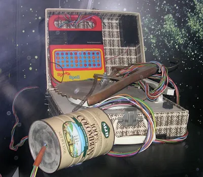
I knew that Alan Yates, VK2ZAY, was just the man for this project. Alan and I met up several years ago when Billy and I spotted and built his Trivial Electric Motor (we still have it, and occasionally fire it up to amaze visitors). On SolderSmoke 102 I mentioned the possibility of a one transistor QRSS transmit station. Obviously this would require some sort of mechanical keyer. I thought of a clock drive. Alan pointed out the in the 1982 Steven Spielberg movie, ET had used a saw blade as his mechanical modulator (see above). Alan also had some intriguing ideas of his own:

G'day Bill,
Thanks again for noticing my QRSS signal making it through to Europe.

Your talk about mechanical solutions for QRSS modulators immediately

made me recall "E.T. the Extra-Terrestrial". The "Phone Home" device he
built had a modulator based on a sawblade IIRC - its been years since I
watched that 1982 classic.

One easy hack might be to use an AC synchronous motor out of a gobo
rotator (for example, I got one out of a fibre optic christmas tree that
expired from overheating). Its reduction drive results in a fairly slow
rotation which might drive a modulator plate. You could do the pickup
optically using a LED/photodiode (or transistor, or even an LDR I guess)
transmission pair. Electrical contacts would work too, but doing it
optically probably means it would have a longer life.

A tape loop system might also be practical and would allow long
modulations to be encoded at reasonable tape rates. A syncro-drive gobo
has to be turned fairly slowly and pushes the "density" of the data
fairly high so the mechanical or optical sensor gets harder to just
throw together. I am sure a clockwork driven disk could be made to
work, it just might have to be fairly large.

Mechanical readout might be a microswitch and holes in the plate, or
even using PCB material with the pattern on it (etched or masked), and a
brush contact. To minimise wear a brass small roller held against disk
with spring tension would work. Oxidation on aging might become a
problem - yeah the more I think about it I am liking optical better.

You can also do it electrically using a diode matrix which can be read
out with some counters. Of course that defeats the original purpose
which was to make a single transistor QRSS beacon with a mechanical
modulator.

One completely insane idea that just occurred to me is to build a slow
mechanical oscillator (say driven by a Stirling Engine or a Curie Point
Pendulum heated by a small candle) and modulate the RF oscillator with
that. The mechanics or thermal system might directly effect the RF
oscillator frequency. Who will make the first candle-powered QRSS
beacon with thermopile PSU? :-)

Regards,
Alan
http://www.vk2zay.net/

Monday, March 2, 2009

Homebrew WSPR from W3PM

Recently I've been reading with envy the WSPR reports from K6HX. Mark tells how he walks into his shack each morning and is greeted with signal reports from around the world. Beautiful maps are presented, with lines arcing from Southern California to distant islands in the South Pacific. I burn with envy. I want to WSPR too! But I have no SSB gear for 30 meters, and unlike our beloved visual MEPT QRSS, WSPR requires SSB gear.

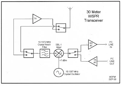
I had mentioned all this on SolderSmoke, and this morning Gene, W3PM, came to the rescue. He sent info on a really interesting and very simple SSB transceiver. Take a look at the block diagram. On transmit it is essentially a DSB rig with a filter at the operating frequency to knock down the unwanted sideband. On receive it is a Direct Conversion receiver preceded by a narrow filter that allows the WSPR frequencies through. It uses the familiar SBL-1 mixer. The filter has only one crystal. And --icing on the cake -- Gene built his version in modular form, with each module in an Altoids tin. Clearly, this is the WSPR rig for us!

Gene provides a very nice write up on his project here:
http://www.knology.net/~gmarcus/WSPR/wspr2.pdf

Sunday, March 1, 2009

Gil Cartoon of W7ZOI on the Mountaintop

Steve, WA0PWK, sent this one in. He found it in an old issue of "Hints and Kinks." Note the callsign on that FB HB portable rig. Wes tells me that this cartoon was actually a Doug DeMaw initiative. Doug took an older cartoon by Gil, W1CJD, and put "W7ZOI" on the rig. The drawing appeared next to a short article by Wes about an electronic keyer using a pair of 741 Op Amps. Wes also reports that his kids got a real kick out of it -- his son Ron was taking an elective printing course in Jr. High School at the time, and printed up a bunch of W7ZOI QSL cards featuring the modified Gil cartoon.

I thought that Steve, N0TU (now WG0AT !), would find this especially interesting.

SolderSmoke Podcast #102

For the podcast go to:
http://www.soldersmoke.com

For the new SolderSmoke Store:
http://www.cafepress.com/SolderSmoke

In SolderSmoke 102:

In the shadow of Vesuvius...
...then back to the "laboratorio."
-------------
QRSS musings:
1 transistor for transmit, 100 million for receive.
We need a low tech beacon generator -- maybe mechanical clock driven?
QRSS on "Hack-A-Day."
VK2ZAY QRSS booms into Europe.
Soul in the New Machine: Billy's oscillator.
ON5EX's grabber on SolderSmoke blog.
Italians at the forefront of QRSS.
--------------
T-shirt news: "Menus are for restaurants!"
"QRSS Ops Do it Very Slowly"
--------------
Using iGoogle for ham radio.
USENET is going strong!
Back on Echolink.
--------------
Minimalist Radio:
The Gnat! The NS-40!
I add a second transistor to my ET-1 (and hang my head in shame).
--------------
MAILBAG:
Jim, AL7RV, developing smoke generator for LTSpice.
Randy, K7AGE, sent Empire of the Air video -- Thanks!
Jim, K9JM, prescribes higher Q for regen rx. "Never will be a 2B!"
Rye, K9LCJ, "Low Space Means Fine Teletype."
Alan, W2AEW, Listens to SS while on the road with Tektronix.
Dave, W8NF, "Armstrong, A Man of High Fidelity." Indeed.
Mark reports W7ZOI releases new EMRFD software.
Jonathan, KB1KIX, Shep fan, has good Smith Chart stuff on his blog.
Jerry, NR5A, building a QRSS beacon.
George, K8VU, Dilbert has "utter social ineptitude."
David, VK6DI, moving East.
Paul, K3PG, took Willamette project on ski trip.
Steve, WA0PWK, Gil cartoon about Wes.
---------------------------

Saturday, February 28, 2009

Out of the Ozarks... The NS-40!

I think this new rig is really interesting. NS stands for "No Simpler." It has only 14 parts. The coils are etched into the PC board (see above) -- I've never seen that before in an HF rig. It runs Class E and puts out 5 watts! The Designer is David Cripe, NM0S, and a kit is available from the 4 States QRP Club for only $30. Look here for more details:
http://www.wa0dx.org/wa0itp/ns40.html

Friday, February 27, 2009

Out of the Sonoran Desert... The Gnat!

We've been away for a few days, down in the shadow of Vesuvius, but I'm back in the shack now, and this morning I've been looking more closely at the latest creation out of the Sonoran Desert:
Chris Trask, N7ZWY, has given us the design for an amazing rig he calls "The Gnat" (Chris has a deep interest in the flora and fauna of the Sonoran Desert.) Like the ET-1 and FETer, The Gnat is an HF transceiver using only one active device. Chris uses a 2N2222 transistor. But unlike the other one-device rigs, The Gnat uses no switches or relays for T/R transitioning -- his rig goes from Receive to Transmit just by pushing the key down. The receiver is, of course, a regen. And get this: The Gnat can produce somewhere in the area of .5 watts to 2 watts of RF. Wow, that's one big bug! There's definitely a lot of Knack in The Gnat. Check it out:
http://www.home.earthlink.net/~christrask/Gnat%2040.pdf

Monday, February 23, 2009

QRSS on HACK-A-DAY

Eliot over at Hack-A-Day was kind enough to run an article about our QRSS exploits. I figured this aspect of the hobby would be intriguing for the more computer oriented folks who visit that blog. Judging from the comments, I think I was right.
Check it out:
http://hackaday.com/2009/02/22/qrss-radio-amateurs-slow-speed-narrowband/

Sunday, February 22, 2009

Happy 6L6 DAY!

Cory, WA3UVV, sent in this nice article about a beloved vacuum tube:

Say "73" to the 6L6


Sometime in the spring of this year, the 6L6 will celebrate it's 73rd birthday. Originally conceived of a year earlier by engineers at General Electric, it represented a new design in receiving tubes (more about that later) and used the recently developed metal case(envelope), instead of glass. RCA was licensed to manufacture it and the first ones hit the market in 1936.

Originally thought of for audio use, it could give you 30+ watts of RF if used in a single-tube oscillator circuit. Not bad for a "receiving" tube - a general name used for things that were "low power" when thought of in comparison to broadcast radio transmitter power levels. It quickly became the most popular tube for ham transmitters for many years to come.

In a fairly short period of time, the 6L6 was also produced in a variety of glass envelopes. In fact the basic 6L6 went through many changes and upgrades as it went through life. RCA moved the plate connection to the top and the 807 was born. This power house, when given 600 volts on the plate could manage 60 watts without breaking a sweat. So much in use, the term "807" was once a popular ham nickname for beer. Technology marches on, and eventually the 807 was succeeded by the shorter 6146. The 6L6 saw it's life increased as the 6LQ6. Both of these tubes were quite popular, as well. Used in sets in kilowatt-level amplifiers with over 1,000 volts on the plates, they also showed up in pairs as finals in hybrid rigs in the 70's. I have a Handbook from 60+ years ago with a circuit for a one-tube 6146-based, 75 watt crystal-controlled transmitter. Don't try that with anything less than a FT-243 crystal...

The 6L6 also had lower rated siblings, the 6V6 (popular with Novices and used in some commercial designs like the Ameco AC-1 transmitter kit) and the 6K6 (very QRP-friendly). "Circle of Life" fans will note that 6L6's still enjoy use everyday, although primarily in audio amplifiers for those who like the glow and "warmth" of the the sound. You can find them at music stores for $50 a pair and up or at hamfests and Ebay for much more reasonable prices.

While I don't know the exact date the 6L6 arrived, March 14th is the 73rd day of the year. There's still time to celebrate the 6L6 by building a rig and putting it on the air that weekend. A straight key is strongly suggested. A quick perusal of the League's searchable QST database (you are a member, aren't you?) will turn up many design ideas and possibilities. Even if you don't have a spare 6L6, 6V6, 6K6, etc. to play along, they're easy to find. (In fact, I'm sure I have a spare for someone who wants to build his own rig in the coming weeks.)

Power supply? A 6 volt filament supply is easy - you can even use some wall warts for that. Coming up with 150 to 600 volts may be a bit more daunting, but if you have a tube-based receiver (makes a nice companion) you can carefully borrow some B+ for a low-power version. Or, go to the "everything we sell is a dollar, so please don't ask how much it is" store and pick up some 9 volt batteries. If you buy 15 packs of 2, you can click them together and come up with 270 volts for (wait for it) $15.

Hey, don't touch the ends to see if it's hot - it's still 270 volts and is dangerous if not respected! Pick up 15 more packs and you'll have a real rock crusher on the air.

If you've never gone on the air with tubes, here's a fantastic opportunity to mark "73 to the 6L6 Day" (or something like that). Remember, real radios glow.

Saturday, February 21, 2009

W3JDR 's LTSpice NE602/SA612

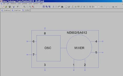
Here's something we've needed for a long time: an LTSpice model for the ever-popular NE602/SA612 chip. Joe Rocci, W3JDR, developed this one back in December. You can download it, along with the LTSpice program (free!) from links on Joe's page:
http://w3jdr.ham-radio-op.net/ Thanks a lot Joe!

Speaking of Spice, Jim, AL7RV, has been e-cursing me for getting him involved with this highly addictive program. Jim has come up with an ingenious idea for making the simulation experience more realistic. I will tell you all about it in the next podcast.

Friday, February 20, 2009

The Reggie Works a DX Station!

There it is. Finally we see it. The famous Reggie of AA1TJ. With an awesome 80 milliwatts of 80 meter RF, Mike yesterday worked the Bahamas with his highly unusual rig. For more details visit Mike's always inspirational web site:
http://mjrainey.googlepages.com/reggie

Wednesday, February 18, 2009

WA5DJJ's QRSS Beacon: Immediate Success!

Here's a story that really captures the fun of QRSS, the way in which this mode can be both high tech/DSP-ish and low tech/minimalist at the same time. It also shows the global reach of the fraternity that supports QRSS. In SolderSmoke 101 I reported on the QRSS building project of Dave, Wa5DJJ. He was building a rig based on a design by the esteemed Maltese radio wizard Stan, 9H1LO (Stan appears in the SolderSmoke slide show -- he is the guy in the lab coat.) You'll recall Dave's comment on how upside down FSK might be useful in reaching our brothers "down under." Yesterday Dave put his new creation (see above) on the air, and posted a message to the Knights of QRSS Yahoo Group. In Belgium, Johan, ON5EX, saw Dave's message and decided to check W8LIW's receiver (via LIW's online grabber). Johan saw Dave's signal and reported the success to the Knights.
You can read more about Dave's project here:
http://www.zianet.com/dhassall/QRSS.html

Here is the e-mail exchange between Dave and Johan:


Tuesday, February 17, 2009 7:46 PM
From:
To:
knightsqrss@cnts.be

Hi Dave, I can see your sigs are on the Ohio W8LIW grabber right now, with a little downward shifting. Well done! Your website truly reveals a keen QRP-er and homebrewer. BTW: I’ll be firing up my first RockMite (20) soon! 73, Johan on5ex


From: knightsqrss-bounces@cnts.be [mailto:knightsqrss-bounces@cnts.be] On Behalf Of David R. Hassall
Sent: woensdag 18 februari 2009 1:30
To: knights QRSS
Subject: [Knightsqrss] WA5DJJ on the air!!

Dear Gang,

First test of my QRSS 10.140Mhz MEPT. It should be around 1.060 on the waterfall. Power output is 122mW (All I could squeeze out of my poor little 2N222A final. Keying is up shift, at about 5 hz. I hooked it to my 30 Meter Inverted Vee off my tower. Apex is at 40 feet. I think I have it right and hope it doesn't blow up. We shall see when I get some reports. I will have pictures on my website as soon as I can get them there. Thanks for all the advice and help. This was a really fun project. Now to get a couple more built to get some others on the air.

73 Dave

------------------
BTW: I succeeded in putting Johan's grabber output onto this blog. Look at top of my right-hand column. If the sun is up over Europe, you should see my upside down FSK around the middle of Johan's screen. (He has the screen kind of split in two to allow more minutes to be displayed, so you should see me in the middle of both the top and bottom halves of the screen. ) You may have to hit the refresh button on your browser to get my blog page to pull down an update of Johan's grabber. Just think about how cool this all is: I transmit a 50 mw sig from Rome with a very minimalist rig. Johan receives it in Belgium using DSP software and puts the results on the www. I embed his output screen on my blog, which you can now see, almost in real time!

Monday, February 16, 2009

Comet Lulin

I don't think I will be able to see this one through the bright and murky skies of Rome, but I may give it a go. Sky And Telescope Magazine has a nice write up that tells you when and where to look. The best night for seeing this one are coming up soon:
http://www.skyandtelescope.com/observing/highlights/35992534.html

Armstrong's Regen (and lots more)

There it is. Howard Armstrong's regenerative receiver. Mike, KC7IT, led me to the wonderful website that has this picture, and much more. The site has all kinds of schematics and pictures and letters related to the work of radio pioneer Howard Armstrong. Check it out (you should probably take the tour by hitting the NEXT button on each page):
http://users.erols.com/oldradio/eha1.htm

I continue to work on my regen (part of the ET-1/FETer minimalist project). Jim, K9JM, says the raspy tone on CW signals is caused by FMing of the regen stage and prescribes a coil of higher Q. Thanks Jim.
Designer: Douglas Bowman | Dimodifikasi oleh Abdul Munir Original Posting Rounders 3 Column