Podcasting since 2005! Listen to Latest SolderSmoke

Saturday, June 15, 2024

Sticker Madness, HI7, April 1

Our friend Lex astutely focused on the date of the release of our report about legal prosecution by the City of San Francisco.  The truth is that we made almost all of this up.  We did put a sticker on a lamp post at Haight and Ashbury.   Dave AA7EE did visit the site and report that the sticker had been removed.  But all the rest was made up.  We did catch several people in this annual April 1 joke.  Unfortunately, not everyone who was taken in was outraged by the city's supposed action. In fact, we got one e-mail SUPPORTING the prosecution.  This fellow said, essentially, that we were getting what we deserved, that we should take this as a life lesson, and stop with the sticker-vandalism.  He was serious.  Jeez.  APRIL FOOL!   We will talk more about this in the next podcast. 

I know the podcast has been delayed by a lot, but I am still getting things set up here in HI7 land.  I hope we will soon be podcasting with particpation from California (N6QW), Northern Virginia (KK4DAS), and the Dominican Republic (HI7/N2CQR).  

Happily, my Dominican ham radio license came through  -- I will be HI7/N2CQR for the next year.  At some point I hope to take the Dominican exam and get a real Dominican call. 

Lex has been our main point of contact in Europe on sticker distribution (aka VANDALISM!). Lex writes:   

Hello all,


Shocked to hear about the "Legal action against Soldersmoke" in podcast : 

https://soldersmoke.blogspot.com/2024/04/soldersmoke-podcast-251-aurora-cbla.html

Which could mean a few things : 
  1. some official is trying to make a career and he will be very busy because there are a lot of stickers in San Fransisco to remove.
  2. somebody did remove the sticker because they are highly collectable and somebody at soldersmoke HQ saw a opportunity to made one of the best april fools jokes in soldersmoke history pulling the listeners (and readers) leg. 
  3. somebody use photoshop and made one of the best april fools jokes in soldersmoke history pulling the listeners (and readers) leg. 

Looking at the release date of the soldersmoke podcast 251, IMHO #3 is the most possible with #2 as a good second. When #1 is the real reason, that sucks big time :-(  (so I'm hoping for the april fools joke outcome)


Let's continue and get on topic to this e-mails subject.

My XYL and I are just back from a holiday to Berlin and aside of the architecture, visiting a large number of museums and historical exhibitions, there was one place on my personal list I wanted to visit : the "Teufelsberg". 

*  The "Teufelsberg" (Devil's Mountain) is a artificial mountain build with rumble of the ruins of Berlin on top of the “Wehrtechnische Fakultät”, covert soil and plated full with trees. In the early 70's the location became one of the most important locations for the United States’ National Security Agency (NSA) outside the United States. The facility monitors Soviet and Eastern Bloc communications and gathers important information on the activities of Warsaw Pact countries. 1992 the side got intrest of creative minds and started to get covert by street art.
More info about the history can be found on there website:  https://www.teufelsberg-berlin.de/en/history/

Not only the historical part of the site, but also because the XYL and I love street art, we took a day visit it. Aside from the nice walk to it, the excellent view and the great pieces of street art, when you are at a site where street art is present all over the place and even is encouraged (and legal) and you "accidently" just happen to have a few soldersmoke stickers in you bag, you just have to use them. So as of this moment, Soldersmoke is present a the formal National Security Agency (NSA) spy station in Berlin. 

I added a few images as a attachment to this e-mail including one to show the great view over Berlin when you on the top deck (only showing one placement, the other 2 are hidden in plane site). 

In short : when you can apricate street art and visit Berlin, a visit to the "Teufelsberg" is almost a must. IBEW bonus : there are a few soldersmoke stickers hidden on the top dek for you to find ;-)

73 from PA 

Lex PH2LB 

mail : lex@ph2lb.nl
home : http://www.ph2lb.nl/   
twitter : https://twitter.com/lex_ph2lb  
call : PH2LB 

"Life's like a role playing adventure. You
need to solve the puzzles first before
they let you go to the next level."


Friday, June 14, 2024

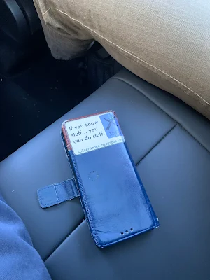
Greetings from Low Earth Orbit


We are in the Dominican Republic for a little while. Yesterday we got Starlink working.   The picture show me holding the cell phone heralding the good news.  I am setting up SolderSmoke Shack South.  More to follow.  

Saturday, June 1, 2024

Farhan Talks Radio Tech at SolderSmoke HQ (EAST) (TWO VIDEOS!)


Great stuff!  We were really fortunate to have Farhan and Humera visit the SolderSmoke East shack after Dayton and FDIM.  Dean and I had a chance to talk BITX with the creator. Here is the two part video.  Most of the tech talk is in Part II (below).  


Farhan and his zBITX

Dean and Farhan with three sBITXs

Dean's homebrew sBITX

Farhan Phone


Wednesday, May 29, 2024

2014 "Off the Shelf" Regen Comes Off the Shelf (Two Videos)

Walter KA4KXX spotted an error in the schematic of my 2014 "Off the Shelf" regen receiver: The source resistor on the MPF-102 should be 2200 ohms, not 2.7 ohms. See:

https://soldersmoke.blogspot.com/2014/09/schematic-for-off-shelf-regen.html
Walter's e-mail caused me to take this old receiver off the shelf. In this video you can listen to it in action on the shortwave broadcast bands. In a second video I put it on the 40 meter ham band and listen to some SSB.


Monday, May 27, 2024

Ham Radio in China -- Interesting info from 高大伟 David Cowhig

Chinese Radio Licenses and Operating Certificates

David Cowhig (aka WA1LBP,  aka Gao Da Wei) was Hambassdor for 73 Magazine on Okinawa when I held a similar "position" on the island of Hispaniola.  David is a real Asia hand, and is fluent in both Mandarin and Japanese.   He is uiniquely sitated to provide info on ham radio in China.  In a recent post he provides this info, and describes how we may soon be hearing from ham Taikonauts in space:  

https://gaodawei.wordpress.com/2024/05/22/2024-ham-radio-in-china-soon-chinese-hams-in-space/

Thanks David! 

Sunday, May 26, 2024

A Really Cool Homebrew Computer


Wow, very cool.  On Hack-A-Day this morning:

It caught my eye because the architecture seems similar to that of the MostlyDIYRF PSSST rig.  

There is a lot to learn from this little machine, especially for an analog guy like me. 

Mostly DIY RF PSSST

Saturday, May 25, 2024

Pete Juliano's Amazing Videos -- 318 of Them!


Blogs come and go, but (hopefully) YouTube is more permanent and accessible.  This morning I re-found Pete N6QW's YouTube channel.  When you use it, I suggest you click on "oldest" first.  This will take you back 14 years,  to Pete's time in the Pacific Northwest.   The video above (him playing guitar) was shot just before he and his XYL moved back to California.  

Here is Pete's YouTube channel:  

This is a tremendous resource for ham radio homebrewers.  It should be preserved and protected. 
Subscribe!  

Thanks Pete! 


Friday, May 24, 2024

Version II of 15-10 Rig -- Updates on Bal Mod, AF amp, and RF Amp, DX

Version II of the 15-10 rig is mostly done. I did a lot of work on the AF amp, balanced modulator, Mic amp, carrier oscillator, and filter. Dean KK4DAS and I continue to test and measure the RF power amplifier. I describe the brutally simple, non-sequenced T/R switching arrangement, and the spread-out open air construction style.

Version I of this rig is on its way to the Dominican Republic. Version II will stay in Virginia. I have already worked a lot of SSB DX with this rig, including, Thailand, Taiwan, China, India, Kenya, Australia, American Samoa, and others.

This video was inspired by the recent work of Nick M0NTV and Charlie ZL2CTM. And of course, Pete Juliano N6QW.

Thursday, May 23, 2024

Charlie ZL2CTM's New Receiver


It is truly a thing of beauty.  

I really like that variable capacitor.  (Where did that come from?  How can I get one?)   

Charlie's calculations on each of the stages is -- as always -- really nice.  

I like the J-310 infinite impedance detector,  Charlie's use of solder wick,  the wooden base, and his decision to keep the circuitry visible.   

I also like Charlie's decision NOT to put that VFO in a metal box.  Too often we see projects that try to convince us that the receiver just won't work unless everything is hermetically sealed in submarine-like boxes.  Not true!  And Charlie's receiver demonstates this.   

Charlie is clearly keeping up the Kiwi tradition of fine homebrewing exemplified by the Tucker Tin 2,  ZL2BMI's DSB rig,  and many other FB HB projects from ZL. https://soldersmoke.blogspot.com/search?q=New+Zealand+DSB

Thanks Charlie!  Be sure to check out the rest of his YouTube channel: https://www.youtube.com/@CharlieMorrisZL2CTM

Wednesday, May 22, 2024

Rigs on Vertical Boards -- Then and Now

 
I saw this on Facebook today.  G1AVQ (SK) Rig

The G1AVQ rig reminded me of the N3FJZ rig that I worked in 2015:

I am a big fan of breadboards, and have recently been following the lead of Frank Jones W6AJF in using pine boards as the bases for my homebrew rigs.  Mine are more horizontal, but we see here from N3FJZ and G1AVQ that a vertical orientation works too.  

Tuesday, May 21, 2024

Laser Communication in London 2007 -- a Pointer, a VW Solar Panel, and Radio Kismet


Hack-A-Day has an article today about using a laser for data transmission.   This reminded me of a discussion I had with Mike KL7R about similar systems.  My son Billy and I built a very simple version in London in 2007.  Check out the podcast above.  Scroll foward to 19 minutes 15 seconds and you will hear how we did this.  

This was Mike's last podcast.  He was killed in a car accident in Hawaii about 10 days later.  RIP Mike.  73 OM.  

Mike KL7R


Friday, May 17, 2024

Band Imaging Rigs (Receivers and Transceivers) -- Video from WA7MLH


In the video above (from 16 years ago) we see Jeff Damm, WA7MLH's  band-imaging receiver for 75 and 40 using an IF of 1.750 MHz and a VFO of 5.2 - 5.7 MHz,  For a signal at say 3.579 MHz (!) you subtract the signal from the VFO and you end up at the IF.  For a signal at say 7.030 MHz you subtract the VFO frequency from incoming signal and get to the IF.  (By the Hallas rule you get sideband inversion on 75/80 meters, but Jeff was on CW so this doesn't really matter.)  

Sixteen years ago this receiver was a work in progress and Jeff was having some trouble with the bandpass filters. I had similar trouble with bandpass filters. Like Jeff, I eventually got this sorted.  

I was happy to see a comment from my friend Joanthan-san on Jeff's old video.  

Jeff has an awesome and rececntly updated QRZ site:  https://www.qrz.com/db/wa7mlh

Band imaging like this is an old idea, and a very good one:  I used a slightly different scheme:   Start out planning on using a single conversion design.  Pick two bands you are interested in.  Select an IF midway between the two.  Build a single VFO that --when added to the incoming (or the outgoing) signal will get you to one of the bands, and when subtracted from the signal will get you to the other one.  Bob is then your uncle.  Two bands, with minimal switching. 

I got started with band switching with my Mythbuster rig:  I would get 75 and 20 meters.  The IF was midway between the two at 5.2 MHz.   My VFO (from an old Yaesu FT-101) ran around 9 MHz.  Boom, it worked, with the added benefit of receiving and transmitting LSB on 75 and USB on 20 with no switching of the BFO/Carrier Oscillator.

Then I did 17 and 12 meters.  Kind of a WARC-band special.  IF was at 21.4 Mhz.  VFO ran around 3.5 MHz.  So by adding the incoming modulated signal 18 MHz signal and the VFO, you get to 17 meters.   By subtracting the VFO from the incoming 24.9 MHz signal you get to 12 meters.  And both are on USB (apply the Hallas rule), so again, no switching of BFO/Carrier frequencies are required. 

Finally,  at solar max, I built rigs for 15 and 10.  Here the IF was 25 MHz.  Again the VFO was around 3.5 MHz.  Adding the incoming 21 Mhz signal to the VFO gets you to 25 MHz, subtraction of the VFO frequency from the in coming 28 MHz signal takes you to 25 Mhz and thus 10 meters.  Again, no sideband inversion (Hallas rule).   Both signals are USB and stay on USB. (I built two versions of this rig -- one stays in Virginia, the other is heading to the Dominican Republic.) 

In the ARRL book QRP Classics, there is an article from the 1990 Handbook entitled "A Band-Imaging CW Receiver for 10 and 18 MHz."  The article may have been based on a receiver built by Dave Newkirk AK7M (Rod Newkirk's son). Unfortunately in the write-up for the ARRL handbook, the drafters repeat the oft-repeated myth about how 9 MHz IF and a 5.2 MHz VFO would supposedly produce LSB on 75 and USB on 20.  This just doesn't work.   But if you put the IF at 5.2 MHz and the VFO at 9 MHz, it does work, as demonstrated by my Mythbuster rig. 

Thursday, May 16, 2024

A Light-beam QSO in Hollandia, Christmas 1944


This old QST article caught my eye, largely because my father was also in Hollandia on that  Christmas day in 1944.  He was in the Navy hospital there, recovering from wounds received in the battle of Leyte gulf (in the Philippines).   Hollandia, also known at Humbolt Bay, is now Jayapura, Indonesia. The picture above shows the harbor in 1944.  Rod Newkirk W9BRD went on to write QST's inspirtional "How's DX?" column for many years. 
----------------- 
From S/Sgt. R. H. Newkirk, W9BRD, "Christmas, 1944" QST, January 1946, pages 25 and 102.

Christmas, 1944


In a wartime world the singular and exclusive camaraderie that exists in the hobby of amateur radio results in so many unexpected and coincidental meetings between good friends, who have previously never seen each other, as to make such happenstance fairly commonplace. But I boast a tale in which time, place and circumstance combined to cause a similar occurrence to be most extraordinary.

The Liberty ship El Segundo Ruiz Belvis lay at anchor in the murky waters of Humbolt Bay, New Guinea, on a tepid tropical night in '44. In the absence of the moon, the Dipper and the Southern Cross scintillated bewitchingly. On the shore, the lights of the army base of Hollandia burned steadily in contrast to the varipowered signal blinkers which intermittently pieced the opaque darkness throughout the harbor. The latter were visual communication between ships and shore plus an admixture of ship-to-ship chatter, official and otherwise. There was an underlying tense tinge to the atmosphere and the stillness was broken only by the sharp staccato of the Belvis' blinker shutters as the signalman transacted port business with the powerful land station.

This was rendezvous. Our Liberty, with scores of army personnel aboard, had here become a unit in the formation of a huge convoy. Crammed into holds, on hatches and into every available nook and cranny of the steel deck, we were Leyte-bound. Stifled, sweaty and hungry on our two meals per day, we wore out deck after deck of pinochle cards and read every available piece of literature over and over again. It was almost a month since we had left Sansapor, scene of our last operation. We were exuberant in the knowledge that we were soon to leave New Guinea.

Christmas was but a few days away and we had had no mail for weeks. Men leaned languidly on the rail and thought of home while others dreamed of the same in their cramped quarters. The circumstances certainly made this Yuletide one to be long remembered. Nevertheless, all that would feature this day for us would be a possible piece of priceless turkey added to the usual dehydrated viands. Just another dragging equatorial day to be piled atop hundreds of others like it.

It was ten o'clock. I was wide awake; only my eyes were tired. Presently, I found myself detachedly reading the blinkers which poked their focused fingers indiscriminately about the bay. My quarters, in the cab of a 399, were on the port rail amidships and afforded a good view across the water. I became absorbed in various bits of chatter between nearby vessels. It struck me that QRM was quite heavy tonight—a sort of an optical 80 meters. I saw one of the lights sign off with a "73." This was interesting as among the host of merchant marine signalmen, hams are spread pretty thinly. I seized my M-1 torch and focused an insipid beam in the direction of that ship. I sent CQ CQ CQ K. A ham call sign is a cumbersome thing to handle with a blinker. Furthermore, I had no faith in the DX powers of my 3-volt flashlight bulb. I was therefore elated when a bright interrogatory sign beamed forth, aimed obviously in my direction. Contact! True, it was outside the hambands, but band divisions in the microwave region are indefinite anyway.

I was still dubious as to whether my man was an amateur. Rather than complicate matters immediately, at this speed of 8 words per minute, I began in the language of the layman: HELLO PAL WHERE YOU FROM? K. Back in an agreeably rhythmic style came: R TULSA OKLA NAME IS HAL K. The given name and place struck a subconscious inner chord vaguely. Next, I blinked: GE HAL IM ROD FROM CHGO K. There was a pause. He reoriented his beam to compensate for tidal drift and then startled me with: W9BRD DE W5EGA K.

The night quickly took on an exhilarant aspect as we lapsed into ham vernacular, spiced with many Morse slaps on the back. Hal Frank was no other than an old c.w. crony of mine. We had heckled each other on 80, 40 and 20 a countless number of times in the prewar days. In memory I was hearing again that beautiful swing and T9X sledge-hammer signal off his three-element rotary. We discovered mutual ham friends and we exchanged much welcome information and recounted bygone days. He was quite amazed to learn that I was behind a mere GI flashlight (with low batteries at that). The QSO continued far into the night—the next and the next.

We seemed destined to rot in our anchorage. The convoy movement was postponed from day to day. However, this Christmas season took on a much different aspect for me as arrangements were made and, at 0900 Christmas Day, my friend, Wilbur Kuure, W9YNY, and I debarked unsteadily down the ladder and made our way across an undulating swell to the Liberty ship Chittenden. There, we met Lt. Hal Frank, W5EGA, personally, for the first time. We all agreed that it was quite a small and bizarre world that December 25th.

Verbal reminiscences cluttered the air within W5EGA's exceedingly neat cabin for several hours. Shelves in his quarters were lined with excellent reading material including many late QSTs. Compared to our situation aboard the Belvis, Kuure and I thought this a bit of heaven.

We were thoroughly acquainted by the time we appeared in the officers' mess. As the cuisine took shape before us and disappeared into our eager gullets, my army pal and I felt somewhat sorry for our less fortunate buddies on the home ship. But such is life. We had, in nautical terms, a "Little Roundhouse," consisting of a generous helping of everything on the menu. We swept our plates clean to Hal's amusement. I remember, most distinctly, the dessert of apple pie and ice cream.

Nightfall found Kuure and me "back to earth" on the Belvis after a most delightful Christmas Day. According to plan, we blinked a "goodnight and thank you" to W5EGA through the twilight. That was our last QSO of that series. Not long after that we weighed anchor and headed for our next stop on the long road back home. Our holiday was over, a new year had begun and there was still a war to be won.


From S/Sgt. R. H. Newkirk, W9BRD, "Christmas, 1944" QST, January 1946, pages 25 and 102.

Wednesday, May 15, 2024

CuriousMarc Looks at Phase-Locked Loops (PLL)


I really like Marc's (AL6JV) videos. It is great fun and very educational to watch him and his team troubleshoot some of the old gear they work on.  There is also a lot of humor. 

In this video Marc delves into the circuitry of the Phase-Locked Loop.  I didn't know that the PLL circuitry has its origins in the space program.  NASA needed a circuit that would permit very narrow band reception of a signal that was undergoing the kind of Doppler shift that spacecraft produce.   Viola! Enter the PLL.  Far beyond Apollo, PLL circuits started to show up in ordinary radio gear.  The General Electric (and JC Penny!) CB transceivers that we rescued from 11 meter infamy used PLL as the frequency determining circuit. 

Marc gives a really good explanation of how the PLL circuit works.  Thanks Marc. 

However, Marc gives an incorrect pronuniation of "kludge" (it should sound like fudge).  But he is a computer guy and is originally from France, so all is forgiven.  He also redeems himself by making fun of the inaccuracies that appear in what he calls "data shites." 

Monday, May 13, 2024

Ragnar LA1UH's Wonderful Museums in Norway


Here are two more great museum visits by Helge LA6NCA.  In these two he visits Ragnar LA1UH.  

Ragnar has a lot of maritime experience, so we see a lot of older ships' radios.  But his interest in the radio art is much broader and we also see a lot of other kinds of gear: 

-- Wow,  a "travel radio" in a suitcase from 1927.  Was this the idea that later lead to the Parasets of WWII? 

-- Lots of "Stay Behind" gear from the Cold War. That "Africa" receiver (that never made it to Africa!) is very interesting. 

-- We see an ART-13 with autotune, ANGRC-9s, several ARC-5 command sets.  I was hoping Raganar would fire up a Dynamotor, but no. 

-- I spotted a Galaxy V transceiver.  I have the VFO reduction drive from one of these in my homebrew 15/10 rig.   

-- We see several variometers in the emergency (500kc?) maritime transmitter.  I used a variometer in my super-simple ET-2 transceiver (with an N0WVA receiver). 

-- Lots and lots of tubes. 

Ragnar says he himself is of 1944 vintage. I hope some "stay behind" provisions have been made for these amazing museums. 

Thanks to Helge LA6NCA and to Ragnar LA1UH.  

Saturday, May 11, 2024

Jens OZ1GEO's AMAZING Radio Museum


Brace yourselves.  This is just too much, too much radio history, too much cool stuff.  We are into ham radio sensory overload territory here. The rigs, the radios, the radioactive stuff (including tubes!).  Lots of Whermact stuff.  A Chinese receiver.  Tesla coils and Faraday shields.  Much more. 

Thanks to Helge LA6NCA for alerting us to this and for shooting these videos.  And thanks to Jens OZ1GEO for putting this magnificent collection together.  I hope they find sometplace to keep this all together so that future generations can benefit from it. 

George WB5OYP points out there is more from Jens here: 

Helge SM/LA6NCA Activates Colorburst Liberation Army in Sweden!


FB Helge.   This is really cool.  I didn't realize until I saw the schematic at the end that he was on 3579 kHz -- that is the old color-burst frequency, and now the frequency of the Color-burst Liberation Army. 

It was challenging to do this without sidetone.  But there appears to be a bit of room left in the matchbox -- could he squeeze in a few more components for a rudimentay sidetone?  Maybe just a piezo buzzer across the key? 
VIVA EL CBLA! 

Friday, May 10, 2024

Wednesday, May 8, 2024

Why we have "BW Limit" Switches on our Oscilloscopes

Dean KK4DAS asked me why we have these switches on our 'scopes.  I didn't know.  Dean asked Alan Wolke W2AEW.  Alan knew: 

Alan Wolke wrote: 

Interesting background on the 20MHz vertical BW selection. This feature has existed on the vast majority of all oscilloscopes since the 50s or 60s (both analog & digital). When I explored the history of this, I spoke to some of the folks at VintageTek.org, and wound up having a chat with THE engineer that did it first!  Tt was John Addis, designer at Tektronix. 

At the time, Tektronix was located in Portland Oregon. While working on a wideband vertical preamp for a new scope (the 7A11 vertical plugin for the 7000 series scope), John Addis was plagued with interference from the local television broadcast station in the 50MHz band. So, he popped in a 20MHz low pass filter that he could switch in/out so that he could complete the work on the preamp. Since it was deemed useful, it was left in the design. 


And, since Tektronix added a switchable 20MHz low pass filter  in their scope, and Tek was the leader in oscilloscope technology, other manufacturers followed suit, and this feature has "stuck" as a staple in vertical setting controls. 


The main reasons you'd use this filter would be to improve the signal to noise ratio (SNR) for signals when their frequency content is below 20MHz.   You've probably noticed that, even without any signal connected, the thickness of the trace is thinner when you engage the 20MHz filter. 

---------------------


Alan sent a link to a Wiki page about the 7A11 that John Addis was designing.  Alan says this places the initial inclusion of the 20 MHz BW Limit filter to the mid 1960s: 


https://w140.com/tekwiki/wiki/7A11


Thanks Dean, thanks Alan!  

Saturday, May 4, 2024

W4YWA's Homebrew Rig on 20 Meters


Ed W4YWA is far too modest -- he has built a very FB homewbrew transmitter.  Congratulations Ed.  I think your original plan to use a Web SDR receiver will work, if you and the other station are just willing to pause for an additional second or two to let the internet catch up with the real world.  Also, you might find some Web SDRs that have less latency than other.  You could used a little SW receiver or a simple buzzer for your sidetone ( I think sidetone is your most pressing latency concern.)   My suggestion is to try to get a few contacts using the Web SDR (perhaps via schedule -- try the DX Summit or the SKCC web page to set some up). Then build yourself a simple Direct Conversion receiver to use with this rig.  You don't have to try to build a VFO at 14 MHz (that can be difficult) -- you could build one at 7 MHz (use the circuit from our High School receiver project) and pair it up with a "Subharmonic Mixer" so that you can tune the 20 meter band.  Please keep us posted on your progress. 

Ed writes: 

Home-Brew Fun and Failures 


I’m not much of an amateur radio operator, but I enjoy the electronics, self leaning, and the home brewing aspects of our hobby. Here’s an account of a recent effort. While trying to re-learn CW, I discovered web-based SDR sites with waterfall displays, all kinds of filtering and better performance than any of my vintage station receivers. So, I start thinking….. if I had a little transmitter and a simple antenna, along with internet access, I’d have a capable station to take on vacations to the beach. Yes I know, there are web based amateur radio stations, but remember the operative words here are: “Home Brew.” After pinging the Google machine, I came up with a two-stage 1-1/2 watt transmitter sometimes refereed to as the “Universal QRP transmitter,” or the “Little Joe Transmitter.” There’s lots of variations of this circuit but it is essentially a Colpits crystal oscillator coupled to a class-C PA. I chose 20 meters because I didn’t want to hire an arborist to string my antenna. My design modifications included a transistor switch that keys both the oscillator and PA, a VXO circuit, power transistor protection, and a 5-th order Chebychev low pass filter.

Notice the (do I dare say, good looking?) enclosure. In a former life, it was a SD card reader from a defunct PC. FYI, gutted CD/DVR drive cases also make fine enclosures for your home brew projects. I opted for a “foil side up – without holes” for my PCB design. All the parts are soldered down on the lands - no PCB holes. I wanted to change parts without having to do open heart surgery. Functional placement was also important to me. I took more time than I’d like to admit to organize the circuit layout as I did, but I’m glad I did.


When all was said and done, it was time to power it up and….. and …. nothing! Not a single function worked! I won’t bore you with the debug stories that took forever, but the only part I didn’t have in my junk box was the PA transistor. I got 10 of them for $5 off the Internets and they all failed to deliver. I could only get a few tenths of a watt from my design. In a fit of desperation, I un-soldered a PA transistor from an old CB radio and it immediately gave me 1.8 watts of pure CW ! ! ! ! Happy dance, happy dance! But, save your accolades. There were lots of other problems; they were my problems not component issues. For example, before you design your own RF filter be sure you understand cutoff frequencies. They are not the same for every filter design. I suggest Paul Harden’s NA5N site to learn about PA output filters. My first few filter attempts had the transmit frequency well down on the attenuation curve. I was attenuating my own signal ! So, after weeks of “why don’t the damn thing work,” I got a clean signal. Whoo-Hoo!


Now it was time to unshackle the dummy load and see where I can be heard. And, Oh boy… I’m beaming into Pennsylvania, Georgia and Northern VA, all from an inverted V on a tripod mounted paint stick, held apart with two tent stakes. But then, reality took over. My grandioso plans for using the web-based SDRs as a station receiver (and the side tone oscillator for my transmitter) didn’t account for the latency delays of the SDR software. If you ever listened talk radio and the host says, “Turn your radio off – the delay will make you sound like a ….” you know what I’m talking about. You would think that someone who over thinks everything, would have foreseen this issue before spending countless hours of breathing solder fumes? Humility and eating crow are my better traits. But not to worry, I’m not ready to give up. Stay tuned for more adventures of Home-Brew Fun and Failures. 

73s W4YWA

Thursday, May 2, 2024

Chuck Adams' Modification of the MXM Simple Transceiver -- An Early QSO with the MXM Thirty Years Ago

Click for a better view

Esteemed Homebrew Hero Chuck Adams AA7FO saw me struggling with the T/R switch on my hamfest-found MXM SupeRX/TX transceiver. Chuck kindly sent me a modification of the circuit that allowed for automatic T/R.  I see it also envisioned the use of a VFO.  We are not sure if this version of the MXM transceiver ever made it to market, but it certainly would -- in any case -- be of interest to homebrewers.  

Chuck wrote: 

Attached is a schematic I drew for Bruce almost 30 years ago with a program that I wrote.  This is for the Simple Transceiver where Bruce and I worked out the solid state switch to replace the slide switches you have to use to switch between receive and transmit.

BTW.  MXM stand for 1990, the year Bruce started his kit adventures.  I worked Bruce on the first beta build of the transceiver Denton TX to Smithville TX on 40m during the day.


Thanks a lot Chuck.  

Wednesday, May 1, 2024

KE5HPY Builds a QRP Transmitter


FB Chuck, very cool.  Please send us more reports on this rig.  
Chuck has been on the blog many times, with many projects: 
73  Bill 
-------------

Bill/Pete:


Thought you would appreciate a recent project inspired by the fabulous EMRFD.  This started as a test bed W7ZOI universal tx to evaluate my stock of RF BJTs and employ some FT-243s in the shack.  That was interesting by itself but the 16-32 dBm output (choice of device really matters!) did not reach the intended targets using my 40m dipole.  So, add a W7EL RF PA and a nifty, clean 7W emerges after damping output from Q2.  The final is pleasantly efficient and needs only a modest heatsink to survive key down for 60 seconds.  KFS then reported S7-9.  Success.  Time to box it up and go XTO, add a meter output at 30dB down and an RF driven LED indicator.  Left room to add an ATtiny85 CQ keyer but ran out of time.  Had to move house and knock down my 40-6m antennas.  That was the most painful part of moving.  So this rig sits while I find a new place to hang antennas.  Eventually, the TX will get a RX mate when it is possible to box up a 40m DC RX with Si5751 and OLED display. Am still trying to solve how to mount an OLED display cleanly in an aluminum box. First, I have to reconstruct my workbench.


Keep up your good work, and that is no April Fool’s joke. 


73,


Chuck KE5HPY


Monday, April 29, 2024

Old Tricks, Lore, and Art -- Freezing and Baking our LC VFOs -- An Example from Cuba


Pavel CO7WT explained why Cuban hams used a process of thermal endurance to improved the frequency stability of their homebrew rigs: 

  --------------------

I'm CO7WT from Cuba, I started my endeavor in ham radio with a islander board.

They (FRC, like ARRL but in Cuba) made a print of a PCB to build the Islander, with component numbers and values, making construction fool proof, I think it was on the 90 or end of the 80...

Mine was built with scraps from an old KRIM 218 Russian B&W TV as Coro's explain, later on I get the 6bz6 and 6be6 tubes for the receiver (this worked better than the Russian parts) the VFO was transistorized, made with Russian components. A friend CO7CO Amaury, explain me a trick: thermal endurance:

For a week put a crust of ice on the VFO board by placing it in a frosty fridge during the night. Put them in the sun by day. This indeed improved stability, this was an old trick.

By thermal endurance I mean improving thermal resistance vs tolerance, meaning that tolerance doesn't vary as much with temperature changes.

 It's crazy, but it worked!!

I remember that my vfo was on 7 MHz, with Russian kt315 as normal Russian transistors and capacitors, nothing 1-5%, 20% at most, it ran several khz in 5-10 min, mounted on a Russian "Formica" board (no PCB) and wired underneath.

After that treatment to the complete board with components and everything, including the variable capacitor; I managed to get it to "only" noticeably in the ear after 30-40 minutes.

To me it was magic!!

Basically, what I'm describing is just "thermal annealing", but Cuban-style and with more extreme limits.

In a refrigerator you could easily reach -10 c and in the sun for a day in Cuba 60-80 celsius at least.

In Cuba in the 1990s-2010s many designs of DSB radios proliferated, both direct conversion and super heterodine (using an intermediate frequency)

At first tubes and then transistors, mostly using salvaged parts, so it was common to find 465/500 kHz (if common Russian) 455 khz and 10.7 Mhz with or without "wide" filters since narrow filters for SSBs were not scarce: they were almost impossible to get.

Not only that, crystals, ifs, PCBs, transistors, etc.

Then, around the 2000s, Russian 500 khz USB filters began to appear (from Polosa, Karat, etc. equipment from companies that deregistered and switched to amateur radio) and that contributed to improving... Even though at 7 MHz 500kc if is very close.

I made many modifications with the years mostly from 1998 to 2004 ish... better filters in front of the first RX stage (same IF described between stages) improved selectivity and out of band rejection, remember we had on that days broadcast as low as 7100 khz

Tx part was a pair of russian 6P7 (eq. RCA 807) in paralell, etc.

The Jagüey and others is one of those evolutions...

 This is something I remember...

73 CO7WT

----------------

This is not as crazy as it sounds.  We can find versions of the same technique in the writings of Roy Lewellan W7EL, Doug DeMaw W1FB, and Wes Hayward W7ZOI.  I found this 2007 message from our friend Farhan VU2ESE: 

I think the word 'annealing' is a bit of a misnomer. the idea is to thermally expand and contract the wiring a few times to relieve any mechanical stresses in the coil. after an extreme swing of tempuratures, the winding will be more settled.
this techniques owes itself to w7EL. I first read about it in his article on the 'Optimized transceiver' pulished in 1992 or so.
but all said and done, it is part of the lore. it needs a rigorous proof.
- farhan

https://groups.io/g/BITX20/topic/copper_wire_annealing/4101565?p=,,,20,0,0,0::recentpostdate/sticky,,,20,1,860,4101565,previd%3D1193595376000000000,nextid%3D1194269624000000000&previd=1193595376000000000&nextid=1194269624000000000


And here is another example of coil boiling: 

https://www.qsl.net/kd7rem/vfo.htm

-----------

I can almost hear it,  all the way from across the continent:  Pete N6QW should, please, stop chuckling.  Obviously these stabilization techniques are not necessary with his beloved Si5351.  Some will see all this as evidence of the barbarity and backwardness of LC VFOs.  But I see it as another example of lore, of art in the science of radio. (Even the FCC regs talk about "Advancing the radio art." ) This is sort of like the rules we follow for LC VFO stability:  keep the frequency low, use NP0 or silver mica caps, use air core inductors, keep lead length short, and pay attention to mechanical stability.  Sure, you don't have to do any of this with an Si5351.  Then again, you don't have to do any of this to achieve stability in an Iphone. But there is NO SOUL in an Iphone, nor in an Si5351.  Give me a Harley, a Colpitts, or a Pierce any day.  But as I try to remember, this is a hobby.  Some people like digital VFOs.  "To each, his own." 


Thanks Pavel. 


Sunday, April 28, 2024

A Soviet Tube in Cuba: The "Little Spider"


I hope readers have picked up on the discussion of the Islander DSB rig out of Cuba. We had a bit of a breakthrough on this recently. I've been writing about it on the blog: 

https://soldersmoke.blogspot.com/2024/04/re-building-islander-dsbcw-rig-in-cuba.html 

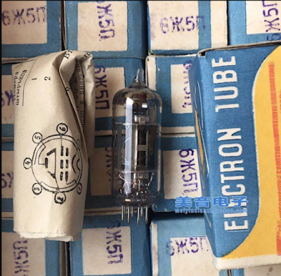
One thing I think is especially interesting:  The Cubans were using parts taken out of old Soviet TV sets.  One of the tubes used in the VFO section of the Islander was known among the Cuban hams as "the little spider." 

Arnie Coro CO2KK explains why: 

"VFO is made with ONE of the 6 "little spider" 5 pentodes... By the way, I am sure you will like to know why the tube is locally known like that... the ZHE letter of the Cyrillic alphabet is something difficult to pronounce to a Cuban - or any other non slavic for the matter - and it resembles like a little spider on the tube's carton and... that's why it is not a 6 "ZHE" 5 but a 6 "little spider" five!!!"

Saturday, April 27, 2024

Cloud Chamber Finale


Today's aparatus (above).  Chamber is larger and I left the bottom sealed.  It sits directly atop a chunk of dry ice.  The spongeat the top is soaked in alcohol. 


This is a one minute clip.  It does seem a bit like watching paint dry, but you will see many atomic particles moving through the cloud. If you look to the right side of the screen you will see that the cloud has started to rain alcohol.  I will put additional clips on the Patreon site. 


Harry Cliff's wonderful book mentions the origins of the cloud chamber. 

Click for a better view. 

Click for a better view/

Here's an interesing site on cloud chambers: 


And here's another one: 


I think that is all I will do on the cloud chambers.  This was a lot of fun, but I am running out of dry ice.  There is, however, a lot of room for improvement and experimentation here, and a project likes this puts you in touch with the earliest days of particle physics (as Harry Cliff explains above). Good luck on 1.22 nanometers! Please let us know how you do. 

Here is one more look at the "output" of my cloud chamber.  This is a ten minute video.   You can see many traces in this. Check it out: 


Thank you Charles Wilson.  And thank you C.L. Stong. 
Designer: Douglas Bowman | Dimodifikasi oleh Abdul Munir Original Posting Rounders 3 Column