Podcasting since 2005! Listen to Latest SolderSmoke

Sunday, December 6, 2015

New Rig: The FRANKENSTEIN Phasing Receiver

Here is my latest project.  I call it The Frankenstein because of the two BNC connectors that come off the side of the DDS oscillator box -- they look to me like the bolts on Frankenstein's neck. The square waves from the DDS LO also seemed to evoke Frank's bolts. There may be other similarities.  We'll see.

Here is the idea:  Phasing,  Direct Conversion, Image Rejecting receiver based largely on the R2 design by Rick Campbell KK7B  as presented in the January 1993 QST.

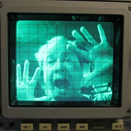
I'm using an AD9850 with an M0XPD Kanga board and an Arduino to generate the quadrature LO signals (you can see the square waves on the 'scope in the background).  I'm using the software of Richard AD7C;  this, combined with the divide-by-4 scheme on the Kanga board,  puts the upper limit of reception at 7.3 MHz.  That's OK for now. 

When I first fired up my AD9850 box I was dismayed to find that the square wave quadrature output was no longer there.  I was about to give up and get anther shield board, but this kind of surrender bothered me.  So I started troubleshooting and isolated the problem to the /4 chips. My soldering of the surface mount chips was, well, a bit dodgy, so I changed to a tiny soldering tip and reheated all those tiny little pads.  Hooray!  I fixed it. 

The receiver will be built mostly on a PC board that Pete made for me back when he was trying to convince me to build a fourth BITX receiver.  I am pleased to put the board to use.   See below.

Yesterday I soldered on the two SBL-1 mixers that will form the heart of this receiver.   I realized that the very robust quadrature square waves from the Kanga board might be robust enough to fry the sensitive little SBL-1s.  Sure enough, I measured about 17 dbm coming out of the Kanga board.   I threw together two roughly 10 db resistive pads.  These should prevent the SBL-1s from releasing their smoke.     

I hope this receiver will be four receivers in one:

1) Standard DC receiver.

2) Binaural Receiver!  Groovy, stereo CW that floats around in your head,  man! 

3) I-Q receiver that can be fed into the sound card of the computer for DSP, panoramic display, etc.   I promise not use it to find fault with the signals of homebrew SSB rigs.

4) SSB image rejecting receiver for easy, Direct Conversion SSB listening without the burden of having to listen to the other side of zero beat. 

There is already a lot of soul in this new machine:  Kanga board with the design my Paul M0XPD, PC board made on Pete's $250,000 CNC machine, and all of it on an actual breadboard (from Italy, I think).  

Rick Campbell and Peter Parker have commented on the allure of phasing rigs.  There is something very attractive about them.  There is a cleverness in the way this design exploits the phase relationships between sidebands to allow us to null out the unwanted side of zero beat.  It took me a while to really understand how this is done -- once I understood it, I really wanted to build a rig that would make use of this principle.    


Saturday, December 5, 2015

Alan W2AEW Hears me on 40 AM with his Drake 2B


Alan W2AEW writes: 

How appropriate! I was casually listening to 40m AM on my refurbished Drake 2B, and I hear the rotation get passed along to none-other than N2CQR - the man that got me excited about the 2B in the first place. FB 20 over signal in NJ, OM! I was able to grab the video camera quickly before you signed off.  Alan's video appears above.

73,
Alan W2AEW
Holy cow Alan,  THE RADIO GODS HAVE SPOKEN!  Clearly you need to get on 40 meter AM.  Maybe get a DX-60 or something.   In your video I spotted several items in your shack that are also in mine:  in addition to the 2B, I see  a Turner +2 transistorized microphone, and that little (very useful) RadioShack speaker. Glad you heard me OM -- thanks for the recording!
73 Bill

Friday, December 4, 2015

The Pleasures of AM, and The 807 (Truly a Bottle Worthy of the Gods)

Sometimes a message posted in the comments section of the blog is so good that it needs to be raised up and converted into a posting all its own.  Such is the case with a message that Rupert G6HVY sent us last month about AM and old rigs.  60 meters eh? Hmmm...

Rupert wrote:

It's always a pleasure to listen to AM QSOs, which hereabouts seem to be mostly on 80 and 60. I bought an FM board for my FT-101ZD with the intention of getting some 10m action, but now I think I'll leave the AM board in (you can't have both) for when I get the beast out of storage. AM, even AM that hasn't been optimised for beautiful audio, sounds so much nicer than SSB.

The other side of AM is to get old military rigs up and running, which is quite the opposite to the golden voice crowd. Another project waiting for time and energy here is an RCA-built Wireless Sets Number 19, which can put out ten watts or so of AM from its 807 (truly a bottle worthy of the gods) - and of course, there are infinite numbers of 50s and 60s vintage thermionic projects in the contemporary magazines. It would be particularly satisfying to find the original PSU for that, as it has two Dynamotors to convert the 24V DC supply to HT, with the transmitter one cutting in when the PTT (sorry, pressel switch) is hit. I say cutting, it actually runs up to speed over a couple of seconds, giving an original 19 Set a very distinctive slow fade-in at the start of an over. Hearing one of those crackling away on 5 MHz is utterly delicious.

Rupert, G6HVY

Thursday, December 3, 2015

Pete Juliano's Simple-Ceiver on Hack-A-Day Today!


Check it out!  Pete's awesome project -- and equally awesome documentation of the project -- is recognized this morning by Hack-A-Day! Congrats Pete!  

http://hackaday.com/2015/12/03/radio-receiver-build-log-and-more/ 

Wednesday, December 2, 2015

Colchester Mighty Mite


GM Bill,

So, I got round to making my Michigan Mighty Mite!

The crystal arrived almost safe and sound, thanks to the USPS’ mail crusher. Perhaps they think that because email and packets can be compressed they can do the same with parcels? (the photo really doesn’t do it justice - the orange area is a large dent…):


No 2 son, Cameron (12), got involved - The extremely neat tank coil is his handywork :


And so to the video: Not only does it oscillate on the correct frequency as shown here, it also has the added bonuses of oscillating around 21.5Mhz (which is the number my frequency counter gives - which caused a great deal of head-scratching on first smoke), and muting the FM broadcast receiver on 96.1MHz on the shelf 3 feet away!. The dummy load is the 3w metal film resistor suspended in mid air.


You might notice more resistors in the circuit itself than the diagram calls for. I chose to have 2 x  20K resistors in parallel to produce a single 10K resistance that could handle .6W. And the poor old 27R .3W resistor got really hot and discoloured before rapidly increasing its resistance ( !! ), so I used 4 (2 serial pairs in parallel) to handle the current. They still get hot, but survive. And the 2N2222a has a bulldog clip heatsink.

Please excuse the uncorrected error at the end of the CQ call!!

This is the second transmitter I have ever built - the other one is a 30m Hans Summers QRSS kit which you also get the ‘blame’ for :-)

Thank-you, Bill. Keep up the good work.

73’s de G7TAT, Colchester, England.


Tuesday, December 1, 2015

Pete's Simpleceiver is DONE! And it is a thing of beauty


Pete's Simpleceiver is a thing of beauty.  And it is done.  And people are already building it: Jim WA7HRG has one in the works.  Go to Pete's blog for more details, pictures, videos, LTSpice simulations etc.  http://n6qw.blogspot.com/  Congrats Pete! 


Sunday, November 29, 2015

A Very Unusual Explanation of AM and SSB -- What Do You Think?

Wow, I've never seen it presented this way.  Am I losing it or is this just completely wrong?   This comes from this web site:

http://www.dsprelated.com/showarticle/176.php


TRANSMITTED SSB SIGNALS
Before we illustrate SSB demodulation, it's useful to quickly review the nature of standard double-sideband amplitude modulation (AM) commercial broadcast transmissions that your car radio is designed to receive. In standard AM communication systems, an analog real-valued baseband input signal may have a spectral magnitude, for example, like that shown in Figure 2(a). Such a signal might well be a 4 kHz-wide audio output of a microphone having no spectral energy at DC (zero Hz). This baseband audio signal is multiplied, in the time domain, by a pure-tone carrier to generate what's called the modulated signal whose spectral magnitude content is given in Figure 2(b).
In this example the carrier frequency is 80 kHz, thus the transmitted AM signal contains pure-tone carrier spectral energy at ±80 kHz. The purpose of a remote AM receiver, then, is to demodulate that transmitted DSB AM signal and generate the baseband signal given in Figure 2(c). The analog demodulated audio signal could then be amplified and routed to a loudspeaker. We note at this point that the two transmitted sidebands, on either side of ±80 kHz, each contain the same audio information.
In an SSB communication system the baseband audio signal modulates a carrier, in what's called the "upper sideband" (USB) mode of transmission, such that the transmitted analog signal would have the spectrum shown in Figure 3(b). Notice in this scenario, the lower (upper) frequency edge of the baseband signal’s USB (LSB) has been translated in frequency so that it’s located at 80 kHz (-80 kHz). (The phasing method of SSB radio frequency (RF) generation is given in Appendix A.)
The purpose of a remote SSB receiver is to demodulate that transmitted SSB signal, generating the baseband audio signal given in Figure 3(c). The analog demodulated baseband signal can then be amplified and drive a loudspeaker.
In a "lower sideband" (LSB) mode of SSB transmission, the transmitted analog signal would have the spectrum shown in Figure 4(b). In this case, the upper (lower) frequency edge of the baseband signal’s LSB (USB) has been translated in frequency so that it’s located at 80 kHz (-80 kHz). The baseband signal in Figure 4(a) is real-valued, so the positive-frequency portion of its spectrum is the complex conjugate of the negative-frequency portion. Both sidebands contain the same information, and that's why LSB transmission and USB transmission communicate identical information.
And again, in the LSB mode of transmission, the remote receiver must demodulate that transmitted LSB SSB signal and generate the baseband audio signal given in Figure 4(c).
Designer: Douglas Bowman | Dimodifikasi oleh Abdul Munir Original Posting Rounders 3 Column