Podcasting since 2005! Listen to Latest SolderSmoke

Showing posts sorted by relevance for query "phase noise". Sort by date Show all posts

Friday, July 28, 2023

Phase Noise and the Radio Amateur

A weak signal disappears in the phase noise of the stronger signal.

The March 1988 QST provides a relatively clear explanation of what phase noise really is:

Highlights: 

Phase noise is an undesired variation in the phase of the signal. In this case, an oscilloscope shows that the time between zero crossings of the signal varies over time when compared to the zero crossings of an ideal sine wave. An exaggerated example of phase noise is shown above.

Phase noise on an oscillator signal has exactly the same effect as frequency modulating the oscillator with noise.

Whenever a carrier is passed through a mixer, the phase noise of the oscillator driving that mixer is added to the carrier.

Phase noise on a transmitted signal causes effects identical to phase noise generated in a receiver.

Any signal that reaches a mixer in the receiver is modulated by the phase noise in the local oscillator driving that mixer. As such, the signal appears to have at least as much phase noise as the local oscillator. Thus, sufficiently strong signals off the receiving frequency can degrade receiver sensitivity by raising the noise floor at the receiving frequency. Receiver dynamic range is reduced as the noise floor rises.

With a frequency-shift-keyed or- a phase-shift-keyed signal, the close-in phase noise limits the maximum bit error rate that the system can achieve. Both of these effects can be quantified once the communications system is defined. With an SSB voice signal, the effects are much harder to predict, but excessive phase noise does degrade SSB signal intelligibility to some extent.

--------------------------------
Receiver guru Rob Sherwood provides some very useful historical background on his web site:

http://www.sherweng.com/documents/TermsExplainedSherwoodTableofReceiverPerformance-RevF.pdf

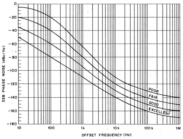
Phase Noise: Old radios (Collins, Drake, Hammarlund, National) used a VFO or PTO and crystal oscillators to tune the bands. Any noise in the local oscillator (LO) chain was minimal. When synthesized radios came along in the 70s, the LO had noise on it. It is caused by phase jitter in the circuit, and puts significant noise sidebands on the LO. This can mix with a strong signal outside the passband of the radio and put noise on top of the weak signal you are trying to copy. This is a significant problem in some cases: You have a neighboring ham close by, during Field Day when there are multiple transmitters at the same site, and certainly in a multi-multi contest station. You would like the number to be better that 130 dBc / Hz at 10 kHz. A non-synthesized radio, such as a Drake or Collins, has so little local oscillator noise the measurements were made closer-in between 2 and 5 kHz.   

-------------------------------------
Experimental Methods in RF Design (EMRFD) has this to say about phase noise:

"The local oscillator is a critical part of any communications system. Modern transceiver performance is often compromised by LO systems that suffer from excess phase noise, effectively limiting the receiver dynamic range. While quiet oscillators, those with low phase noise, can be built using traditional methods, these circuits often lack the thermal stability of a synthesizer.... Frequency synthesis is not, however, the answer to all the LO problems presented to the experimenter.  Some PLL synthesizers are burdened by excessive phase noise. Those using DDS, while quieter, emit spurious outputs, often in profusion.  Both use an excess of digital circuitry that can often corrupt a receiver environment."  page 4.1
   
"At first glance, phase noise sounds like an esoteric detail that probably has little impact on practical communications.  This is generally true." page 4.12 

--------------------------------------

Hans Summers G0UPL analyzed and measured the phase noise of the Si5351a chip: 

http://qrp-labs.com/qcxp/phasenoise.html

------------------------------------

DC4KU appears to be using the crystal filter method used by Hans: 

https://dc4ku.darc.de/Transmitter-Sideband-Noise_DC4KU.pdf

------------------------------------

Martien PA3AKE has done a lot of great work on this topic.  See: 

https://martein.home.xs4all.nl/pa3ake/hmode/dds_pmnoise_intro.html

-----------------------------------

Dean KK4DAS commented on the phase noise video of the IMSAI guy: 

Watching the video I was reminded of Segal's law roughly paraphrased as follows.:

A man with one spectrum analyzer knows his phase noise. A man with two is unsure.

Monday, August 24, 2015

Unfazed! Fight HISS-teria! Give the Si5351 a Chance.

 
Thanks to all who have contributed to our discussion of phase noise and the Si5351 chip.  Let me throw out some ideas -- some technical, others philosophical.

1)  We may be worrying about this too much.   In all of the homebrew or kit rigs we've built over the years, I never recall much concern about the phase noise specs of the LC or crystal oscillator circuit that we were using. What were the phase noise stats on a Heath VF-1? How about the phase noise stats for the little Hartley oscillator in those DC receivers we made?  No one even checked. Our rigs usually worked just fine.  We would have noticed if they were extremely noisy, but if they were good enough, we left well enough alone.  It doesn't really make much sense for us to now be suddenly very concerned about the phase noise stats of the various DDS and PLL chips that are replacing those LC and crystal circuits, especially when the measurements show that they are usually in the same range as our old familiar oscillators.   

2) The perfect can be the enemy of the good, and the "good enough."  We have a long tradition in ham radio of tolerating less-than-perfect or less-than-optimum parts.  Remember, the NE-602 has some shortcomings, but we use it. We use it a lot.  The IRF-510 wasn't even designed to be an RF amplifiers, but we have pressed it into service for our PAs.

3) We should be willing to give a new part a try, and we should be pleased if it proves useful.  We should be wary of untested claims re the unsuitability of a component.  We have to avoid the "works in practice, but not in theory" situation.   If something works well, doesn't create additional QRM,  is inexpensive, and fosters experimentation and homebrewing, we should be happy about being able to use it.  

4) All electronic components -- not just the Si5351! --  produce noise.  Resistors produce noise.  Look at this:
" We can infer... that if we install phase-quiet oscillators in transmitter and receiver, we ought to be able to tune our receiver to a frequency closely adjacent to a very strong signal from the transmitter without encountering anything like phase-noise hiss. Yet, after an exhaustive phase-noise cleanup at transmitting and receiving sites, we test our communication system only to discover that the transmitter still emits broadband hiss! The culprit is transmitted amplifier noise. Just about every modern transmitter or transceiver consists of a high-gain, linear amplifier strip that amplifies the low-level output of oscillators, mixers and phase-locked loops to hundreds of watts or a few kilowatts. Because amplifier circuitry is not perfectly quiet, the output of the transmitter contains noise (hiss) in addition to the amplified signal. Transmitted along with the desired signal, this hiss can degrade the noise floor of nearby receivers-just as transmitted phase noise can. Where does amplifier noise come from? Thermal noise, for one thing. Electronic components operated at temperatures greater than absolute zero generate random electrical noise. This noise is broadband in nature. Greatly amplified in an audio amplifier-or greatly amplified in a radio transmitter, transmitted as broadband radio noise, received and converted to audio-it sounds like hiss. Random variations in electron flow within active amplifier components (transistors and vacuum tubes) are another source of amplifier noise. Transmitted as broadband radio noise, received and converted to audio, it also sounds like hiss." Source: http://www.robkalmeijer.nl/techniek/electronica/radiotechniek/hambladen/qst/1988/03/page14/index.html

5) It seems that whenever a new technology or part comes along there will be those who issue dire warnings about how we can't or shouldn't use it.   When transistors came along, there were those who said that hams shouldn't homebrew with them because -- it was argued -- without spectrum analyzers we couldn't possibly come up with spectrally pure signals. 

6)  We have to be careful lest this obsession with perfection and extremely high tech standards be used as a rationale for not homebrewing, or (much worse) as an argument against homebrew rigs on the ham bands.   There is a bit of this going around.   Get on 40 meters with rig that drifts a bit or that is not "on frequency" to within 10 Hz and you will find out what I mean. 

7)  The Si5351 is a good part for our purposes. It does something new and VERY useful for us:   It can put out BOTH our VFO and BFO frequencies.   It makes it much easier for us to change bands and-or switch between USB and LSB.   Its phase noise figures are fine.  LA3PNA (citing measurements by KE5FX) notes: "The phase noise of the Si5351 is around -130dBc/Hz at 10KHz. This is quite decent, If compared to a Hartley or Collpits you would see little or no difference. Some of my measurements of published free running oscilators show phase noise in the -110dBc/Hz range!" 

Fig 5

-130 dBc/Hz at 10 kHz puts this part on the "good" curve of this chart. From (http://www.robkalmeijer.nl/techniek/electronica/radiotechniek/hambladen/qst/1988/03/page14/index.html

We should give this little chip a chance!   Give it a try! 

Our book: "SolderSmoke -- Global Adventures in Wireless Electronics" http://soldersmoke.com/book.htm Our coffee mugs, T-Shirts, bumper stickers: http://www.cafepress.com/SolderSmoke Our Book Store: http://astore.amazon.com/contracross-20

Friday, August 21, 2015

Going through a phase (on phase noise)

There seems to be a bit of hysteria on the alleged phase noise problems of the Si5351 chip.  The library yields some words of wisdom that help keep things in perspective:

ARRL Handbook (2002) page 14.5: "You would be excused for thinking that phase noise is a recent discovery, but all oscillators have always produced it."

Experimental Methods in RF Design page 4.12 "At first glance, phase noise sounds like a esoteric detail that probably has little impact on practical communications.  This is generally true."  (EMRFD does, however, go on to discuss the problems that arise on both receive and transmit from EXCESSIVE phase noise.)

Our old (young!) friend Thomas LA3PNA e-mailed on this subject noting that the Si5351 chip produces less phase noise than many Hartley or Collpits oscillator designs.   He provides a link to measurements (far better than mine!) of the noise from the Si5351:

http://nt7s.com/2014/11/si5351a-investigations-part-7/

NT7S puts it this way:

I believe that the plots speak for themselves fairly well. If you compare these results to the receivers in the Sherwood Engineering receiver table, I think you'll see that the Si5351 acquits itself quite nicely for such an inexpensive part. Personally, I think the Si5351 is eminently usable for many receiver applications, except perhaps the most high-performance. Certainly for the price, it's going to be extremely hard to beat. I hope this motivates those sitting on the fence to decide if the Si5351 will meet their needs.

Be careful in evaluating statements saying that the Si5351 phase noise is 3-6 db worse than an Si570.  This makes it sound like there is a LOT of noise coming out!  But again, it is important to keep things in perspective:  The noise from one chip might be -156 dbc/Hz while the "worse" chip might be -150 dbc/Hz.  That's still not enough noise to make a lot of noise about.  

The ARRL handbook recommended a very simple check for excessive phase noise:  Set up a very strong signal in the band of your receiver.  Then slowly tune to the signal, listening carefully for any build-up in noise as you approach the signal.  I did this, and I didn't hear any.  As for transmit, well,  as Pete points out, I think the spectrum police on 40 meters would let us know if our signals were broad or noisy!  The ARRL Handbook notes that in a transmitter, "This radiated noise exists in the same proportion to the transmitter power as the phase noise is to the oscillator power..."


Our book: "SolderSmoke -- Global Adventures in Wireless Electronics" http://soldersmoke.com/book.htm Our coffee mugs, T-Shirts, bumper stickers: http://www.cafepress.com/SolderSmoke Our Book Store: http://astore.amazon.com/contracross-20

Monday, July 17, 2023

Going Down the Phase Noise Rabbit Hole with the IMSAI Guy (VIDEO) -- Is there a better way?


Chimera:  2.
a thing that is hoped or wished for but in fact is illusory or impossible to achieve.
(from the Oxford English Language Dictionary). 

Phase Noise.  We know what it is, but how do you measure it?  Pete N6QW and I went through this back when people were casting phase noise aspersions at (Pete's!) beloved Si5351.   More recently phase noise hate  has been focused on (my?) beloved Franklin oscillator.  When I asked a very technically proficient and guy at the VWS club if he could measure phase noise, I was surprised when he honestly said that he could not. 

And now we have the IMSAI guy saying, essentially, the same thing.  Wow, if the VWS guy and the IMSAI guy -- with all the spectrum analyzers at their disposal -- have trouble measuring phase noise, what hope do we ordinary hams have?  I mean, at best most of us have just an oscilloscope, a NanoVNA,  and a TinySA.  

Look, I know that phase noise is real and in certain circumstances, it is important.   But sometimes I suspect that its measurement is also a bit of a technical chimera:  If,  for whatever reason,  there is a circuit that you don't like, you can claim that the phase noise of that circuit is bad.  Or horrible. I think we see this sometimes with the Franklin oscillator.  Very few hams will be able to measure it and dispute the assertion that the phase noise is bad.    

For a perhaps painful walk down SoldeSmoke's "Phase Noise Memory Lane"  go here: 

Thanks to the IMSAI guy for a great video.   But let me ask:   Is there a better, simpler way to measure phase noise?  One that will avoid chimerical results and that could be used by hams with sort of standard ('scope, sig gen, NanoVNA, TinySA) test gear? 

Thursday, October 22, 2015

November 2015 QST -- Wrist Radios, Phase Noise, and a 1958 BITX!


A Early BITX


I liked this issue.  Highlights:

Page 30.  Glen Popiel's article on the Arduino.

Page 33.  I know this may come as a surprise, but in spite of my admitted Ludite tendencies, I found the article on High-Speed Wireless Networking to be very intriguing.   

Page 38.  Hey!  Mike Aiello N2HTT has an article about an Arduino-based CW recorder.  FB Mike!

Page 54.  Review of LNR LD-5 QRP Transceiver. "The LD-5 is actually an SDR in a box with switches and knobs..."  They give a phase noise graph.

Page 58.  Review of Synthesizer upgrade for the Elecraft K3.  Uh-oh.  Phase noise again.  The review says the upgrade results in a reduction of phase noise, but the graphs seem to show an increase in transmitted phase noise on 20 meters as soon as you go 10 kHz from the transmit frequency.  I guess this is a tradeoff for a larger decrease in close-in (less than 1 kHz spacing) phase noise?  But if the objective on the transmit side is to deal with "a major problem with multiple operators in the same band segment in close proximity" resulting from transmitted phase noise,  is this a good trade-off?   Also, it would  have been interesting to know if the reviewer could detect -- by ear -- any improvement in the received signal.  

Wayne Burdick, N6KR, of Elecraft e-mailed us to let us know that there was an error in this QST article.  The original graph in the article showed an improvement in phase noise at close-in frequencies, but it also showed a significant worsening of the phase noise beyond 10 kHz.  THIS CHART WAS INCORRECT.    The Upgrade does, in fact, improve the phase noise performance.  A corrected version of the article appears here:
 
Here is the corrected graph:


Page 71.  My nightmare.  The WristRig.  The Apple Watch on 40 meters.  Sorry Steve, Dick Tracey did not have The Knack, and tackling the "Apple Watch challenge" is not an indication of "homebrew chops."  Software coding chops yes, but homebrewing is, for me, a different thing.   (But, as we always say, too each his own... And thanks to Steve for the interesting article. )

Page 82.  Ross Hull.  Very interesting article, especially the part about OM Ross's untimely death by electrocution.

Page 100.  "The Cosmophones" by Joe Veras.  Cool pictures (as always) from Joe.  And I loved the first lines:  "What in the world is a bilateral transceiver?  Byron Goodman, W1DX, posed that question in his June 1958 QST review of  the Cosmophone 35."    Wow, four months before my birth By Goodman was writing about BITXs in QST!

Monday, September 7, 2015

Si5351 and the Spectral Purity Mask


I was thinking about spectral purity standards and the Si5351 chip. I realized that I didn't even know what the FCC standards for "close in" noise are.   The standards for spurious emissions ARE well known, but these are for harmonics and parasitic emissions relatively far from the desired signal.  What about unwanted signals CLOSE to the desired signal? 

My old 2002 ARRL handbook indicates that the FCC has not established firm standards for this "close in" noise.  (They call it "out of band" noise, but are clearly referring to noise that is close to the desired signal but spreading out beyond the desired bandwidth.  Phase noise would be in their category.)

In the course of my Googling, I found the above spectral purity mask.   I don't know where it comes from, but I think it is the kind of graph that would be very useful to us as we evaluate the merits and shortcomings of various frequency synthesizers.  Would our DDS or PLL rigs fit in this mask?   I think an Si5351 rig WOULD.  According to KE5FX's measurements, at a mere 100 Hz from the center frequency, the Si5351 phase noise is already -90 db.

Does anyone have a similar mask showing current standards?

I still don't understand why so many folks believe that the Si570 is a useful part for homebrew rigs, but the Si5351 is not.  Look at the numbers:

Si570
Clifton Labs  measuring at 30 MHz carrier. At 10kHz from carrier:   -109.6 dbc/Hz
Silicon Labs web site (carrier freq not specified) At 10 kHz from carrier:  -116 dbc/Hz

Si5351
KE5FX measuring at 19.99 MHz. At 10kHz from carrier:  -127 dbc/Hz
Silicon Labs  measuring at 156.2 MHz. At 10 kHz from carrier   -112 dbc/Hz.

Can anyone out there explain the technical basis for the belief that the Si570 is a useful part while the Si5351 is not?   

It is important to keep things in perspective.  ALL of these noise numbers represent VERY small noise levels.   Let's keep is simple and assume a 100 watt carrier signal and a phase noise of -100 dbc/Hz.   That means the phase noise per hertz would be .00000001 watts.  That's watts/hertz.  How much "noise power" would that represent in a typical SSB passband?  Multiply by 2500 Hz and you get 25 microwatts.  That's really low noise levels. Not enough to worry about.  And as we've noted, we've happily used rigs with LC VFOs and crystal oscillators for all these years without every once measuring their phase noise.

Our book: "SolderSmoke -- Global Adventures in Wireless Electronics" http://soldersmoke.com/book.htm Our coffee mugs, T-Shirts, bumper stickers: http://www.cafepress.com/SolderSmoke Our Book Store: http://astore.amazon.com/contracross-20

Friday, June 3, 2022

Phase Noise and all that

Our friend Dave K8WPE has been listening to old podcasts.  He recently came across those in which Pete and I were talking about phase noise.   He asked for some resources on this topic.  Here is what I sent him: 

 Receiver performance expert Robert Sherwood explains it this way: 

Old radios (Collins, Drake, Hammarlund, National) used a VFO or PTO and crystal oscillators to tune the bands. Any noise in the local oscillator (LO) chain was minimal. When synthesized radios came along in the 70s, the LO had noise on it. It is caused by phase jitter in the circuit, and puts significant noise sidebands on the LO. This can mix with a strong signal outside the passband of the radio and put noise on top of the weak signal you are trying to copy. This is a significant problem in some cases: You have a neighboring ham close by, during Field Day when there are multiple transmitters at the same site, and certainly in a multi-multi contest station. You would like the number to be better that 130 dBc / Hz at 10 kHz. A non-synthesized radio, such as a Drake or Collins, has so little local oscillator noise the measurements were made closer-in between 2 and 5 kHz. 

Rhode and Schwarz have a good oversight video with great graphs that explain the fundamentals,  See above or here:  https://www.youtube.com/watch?v=hfgaEjf1154 

I think a lot of the fretting about advanced receiver performance measurements are really kind of over-the-top, and mostly of interest to advanced builders who want the very best performance from their receivers.  Most of the rest of us are happy if we can hear the band noise and separate the desired signals from the QRM.  But I must admit that as time goes on, I find myself getting more and more finicky.  I start to worry about gain distribution and dynamic range.  But I don't worry so much about phase noise because I am more of an LC oscillator guy and don't make much use of the PLL devices (like the Si5351) that do produce more phase noise. 

I've had many articles on the blog about about phase noise.  Here they are: 

Friday, October 23, 2015

QST Error on Elecraft K3 Phase Noise Measurement CORRECTED


Wayne Burdick, N6KR, of Elecraft let us know that there was an error in the QST article about the KSYN3A Synthesizer Upgrade.  The original graph in the QST article showed an improvement in phase noise at close-in frequencies, but it also showed a significant worsening of the phase noise beyond 10 kHz.  THIS CHART WAS INCORRECT.    The Upgrade does, in fact, improve the phase noise performance as shown in the corrected graph above.  A corrected version of the article appears here:
 
Thanks for letting us know about this Wayne.  We have long been big fans of Elecraft and are proud that a picture of your KX3 appears on all of our blog pages under the headline "One of the Best Receivers in the World."

Pete and I will continue our study and discussion of phase noise;  as synthesizers make their way into more and more of our hombrew rigs it is important for us to understand the significance of this parameter.   


Friday, October 30, 2015

Si5351 -- G4GXO says "Give it a go!"


Hi All,
 
Many of you will know of the low cost Si5351A programmable clock generator which can serve as a VFO with a remarkable range of 2.5kHz to 200MHz. This device is available from the larger industrial component suppliers such as RS for as little as £0.68 +VAT and is offered as a small PCB module with regulator and level converters from many amateur component suppliers for around £7.00. I bought a couple of the Adafruit modules to evaluate as the second conversion oscillator in a DSP IF system I’m developing and once I’d overcome the hurdle of writing the dsPIC33 software to drive the device I decided to test the unit as an HF VFO. My reason for doing this was to assess the phase noise of the si5351A; a quick Google will turn up many blogs and forum listings on this subject with mixed opinions of the suitability of this device for VFO service. With no direct method of measuring phase noise I decided to examine instead the impact of phase noise on receiver performance, after all it is this effect that will determine the suitability of the Si5351A as a VFO. My strategy was simple, I used the receiver section of my 60m SSB transceiver which is based upon the Eden IF (SPRAT 144) and uses one of the club 9MHz SSB filters. The front end mixer is a discrete diode ring made from two trifilar wound FT37-43 toroids and four 1N4148 silicon diodes. Unlike a schottky diode mixer this silicon switching diode version requires more drive to keep conversion loss down. The VFO is a low phase noise 7ppm Si570 running on the high side of the IF at 14MHz, a MMIC output stage delivers +10dBm of drive to the mixer. The Si5351A was compared directly to the Si570 – which is a known “very good” performer.
 
The test strategy was to measure the receiver Minimum Discernable Signal (MDS) at 5MHz with the Si570 and the Si5351A as the VFO. With no buffer stage to raise the 5dBm output of the Si5351A to match the +10dBm output of the Si570 VFO module, I accepted that this compromise would have some bearing on the results through increased mixer loss.
 
Results (14MHz oscillator drive, 2.2kHz IF bandwidth)
 
Si570  +10dBm output, MDS –122dBm  (Well below noise from the antenna, perfectly acceptable for 60m!)
 
Si5351A +5dBm output, MDS –118dBm (Note, mixer drive 5dBm down!)
 
Some if not most of the 4dB difference in MDS is without doubt attributable to the lower drive power of the Si5351A in my test configuration, this is borne out by the AGC threshold which moved up by 4dB suggesting increased mixer loss. I’m confident that had I been able to match the +10dBm output of the Si570 then it would have been a close match. My conclusion is that for HF at least the Si5351A is a very useful oscillator which is easily applied and can deliver good performance. If you had doubts about using this device at HF I hope that these results encourage you to give it a go!
 
73 Ron G4GXO

Thursday, August 20, 2015

Si5351 Phase Noise? A Tale of 3 Oscillators

Si5351 at 16 MHz
 
There is still a lot of talk about the supposedly horrible phase noise of the Si5351 chip. In a recent episode of a popular (and very good!) podcast about homebrewing, the podcasters talked about this in the context of some megawatt AM shortwave broadcast stations that had oscillator phase noise problems and were wiping out large portions of the HF spectrum.   I don't think those stations were running Si5351s, but the listener was left with the impression that these handy little chips are very noisy with lots of spurs and will inevitably produce horrible dirty, spectrally impure signals. 
 
This has not been our experience.   Following Pete's lead, several of us are using the Si5351 to generate both VFO and BFO signals in our transceivers, with good results. The receivers sound very good and we have not heard complaints of "broad" or "noisy" transmitted signals.
 
I decided to dig into this a bit.  This was also an excuse for me to use the FFT and screen capture features on my Rigol 'scope.  
 
I now have THREE BITX transceivers in the shack.   My BITX17 uses a VXO at round 23 MHz (IF at 5 MHz)/  My BITX20 uses a classic LC VFO running around 3.5 MHz (IF at 11 MHz).  Finally, my BITX40 (DIGI-TIA) uses the dreaded and much reviled Si5351 running at around 16 MHz (IF at 9 MHz).   I thought that these three rigs would provide a good opportunity to test the scurrilous claims about the Si5351.   
 
As a simple first test, I put my Rigol scope in FFT mode and just put the probe at the VFO Mixer's LO input.  The screenshot above is the FFT for the Si5351.  It looks pretty clean to me.  The 'scope is looking at 15 Mhz above and below the VFO signal.    


VFO at 3.5 MHz
 
Next I measured the output of the BITX20 VFO at the same point (input to the VFO mixer).  (I had to change the vertical range, but the horizontal was unchanged.)  Here you can see the second harmonic (just because at this low freq it is within the freq range setting of the 'scope).  It doesn't look much different than the Si5351.   


VXO at 23 MHz
 
Finally, here is the BITX17 VXO at 23 MHz, again at the input to the VFO mixer.   It looks remarkably similar to the Si5351, don't you think? 
 
More on this to come.  The ARRL Handbook (2002) has a good discussion on phase noise. I am digging into this and hope to do some more tests.   For now, I think we should reserve judgment on the utility (for us) of the Si5351.  


Our book: "SolderSmoke -- Global Adventures in Wireless Electronics" http://soldersmoke.com/book.htm Our coffee mugs, T-Shirts, bumper stickers: http://www.cafepress.com/SolderSmoke Our Book Store: http://astore.amazon.com/contracross-20

Sunday, August 21, 2022

On our 17th Anniversary: SolderSmoke Podcast #179 -- TENTH ANNIVERSARY SHOW -- A Walk Down Memory Lane

On August 21, 2005 Podcast #1 was uploaded to our old GeoCities host. Just prior to that Mike KL7R set up a Yahoo Mail account.  I still use it. Yahoo sent me an e-birthday card! 


I put our 10th Anniversary Podcast on the YouTube Channel today.  Click above. Show notes below 

---------------------------------

22 August 2015

YESTERDAY MARKED 10 YEARS OF THE SOLDERSMOKE PODCAST
-- A clip: The first minutes of SolderSmoke #1
-- A trip down SolderSmoke memory lane.
-- The SolderSmoke lexicon -- words and phrases we use (a lot).

BENCH REPORT

-- Pete's antenna project.
-- Pete's new Blog: http://n6qw.blogspot.com
-- Bill's big amplifier problem fixed thanks to Allison KB1GMX.
-- Six digit freq readout with an Altoids case.

THE Si5351 PHASE NOISE CONTROVERSY

-- ALL oscillators make noise.
-- Keeping things in perspective: It is 100 db down!
-- Observations and tests from LA3PNA, NT7S, and K0WFS:
http://k0wfs.com/2015/08/21/si5351-phase-noise-and-thd-tests-using-an-agilent-e4402b-spectrum-analyzer/

http://nt7s.com/2014/11/si5351a-investigations-part-7/

-- Try it, you'll like it! The benefits trying things on real rigs.

NEWS
Interviews on "QSO TODAY" with Eric 4Z1UG.
Horrible band conditions.
Looking at Saturn with telescope.

MAILBAG

Another recruit for the CBLA: Paul KA5WPL.
Ron G4GXO on Bell-Thorn and Eden9 SSB rigs.
Rupert G6HVY on Kon Tiki radio and Mr. Spock.
Mikele's Croation BITX rigs.
Dean AC9JQ's TIA.
Bryan KV4ZS will build an LBS receiver.
Dave Anderson give Pete good antenna advice.
Steve Smith moves in from the garage.
Pete has built 12 SSB transceivers. Intervention time?
------------------

Saturday, August 22, 2015

SolderSmoke Podcast #179 SPECIAL TENTH ANNIVERSARY EDITION


SolderSmoke Podcast #179 is available:

22 August 2015


YESTERDAY MARKED 10 YEARS OF THE SOLDERSMOKE PODCAST
-- A clip: The first minutes of SolderSmoke #1
-- A trip down SolderSmoke memory lane.
-- The SolderSmoke lexicon -- words and phrases we use (a lot).

BENCH REPORT
-- Pete's antenna project.
-- Pete's new Blog:   http://n6qw.blogspot.com
-- Bill's big amplifier problem fixed thanks to Allison KB1GMX.
-- Six digit freq readout with an Altoids case.

THE Si5351 PHASE NOISE CONTROVERSY
-- ALL oscillators make noise.
-- Keeping things in perspective:  It is 100 db down!
-- Observations and tests from LA3PNA, NT7S, and K0WFS:

-- Try it, you'll like it!  The benefits trying things on real rigs.

NEWS
Interviews on "QSO TODAY" with Eric 4Z1UG.
Horrible band conditions.
Looking at Saturn with telescope.

MAILBAG
Another recruit for the CBLA:  Paul KA5WPL.
Ron G4GXO on Bell-Thorn and Eden9 SSB rigs.
Rupert G6HVY on Kon Tiki radio and Mr. Spock.  
Mikele's Croation BITX rigs.
Dean AC9JQ's TIA.
Bryan KV4ZS will build an LBS receiver.
Dave Anderson give Pete good antenna advice.
Steve Smith moves in from the garage.

Pete has built  12 SSB transceivers.  Intervention time? 

Our book: "SolderSmoke -- Global Adventures in Wireless Electronics" http://soldersmoke.com/book.htm Our coffee mugs, T-Shirts, bumper stickers: http://www.cafepress.com/SolderSmoke Our Book Store: http://astore.amazon.com/contracross-20

Saturday, June 13, 2015

SolderSmoke Podcast 177 Bicoastal Termination Insensitivity Unphased by Phase Noise

 
SolderSmoke Podcast #177 is available:
 
 
13 June 2015
 
-- PETE JULIANO INDUCTED INTO THE QRP HALL OF FAME
-- Bench Reports:  Bicoastal Bilateral Success:  A Tale of Two Tias
    Only 3 TIA rigs in the world?  It depends...
    Relay improvements in the BITX Builds
    Straightening out amp problems
    The many uses of copper foil
    No phase noise or bleed-over troubles
    Plug-in filters
    Adjusting TIA amp gain on RX and TX (too much is not good!)
    Getting the BITX to work with the CCI amp
    Allison wisely prescribes 3 db pads 
    Curing hum by moving the power supply (duh!)
-- Farhan's New Minima -- Crying out for an Si5351?
-- Mike KL7R's Web Site is Back (thanks to W8NSA)
-- SolderLex: Rigs or Radios?  We go with Rigs
-- A ham rite of passage:  Build a Dipole!
-- What does your shack look like at the end of a project?
-- MAILBAG 
    The CORRECT pronunciation of Belthorn
    Multiplication and Division by 4
    W8NSA, Vietnam, a Transoceanic and a 9V Battery 


Our book: "SolderSmoke -- Global Adventures in Wireless Electronics" http://soldersmoke.com/book.htm Our coffee mugs, T-Shirts, bumper stickers: http://www.cafepress.com/SolderSmoke Our Book Store: http://astore.amazon.com/contracross-20

Friday, July 30, 2021

Video: Rob Sherwood NC0B on Transceiver (and Especially Transmitter) Performance

 Rob Sherwood NC0B is one of the real authorities on receiver performance.  Many of us have relied on his ratings of commercial receivers for many years.  His recent presentation to the Madison DX Club has a lot of really interesting information. There is also, I think, some stuff that homebrewers will find distressing. 

Just some things that I noticed: 

-- Rob mentioned a move back to 9 MHz IF filters and a move away from dual-conversion rigs with a high IF.  He also mentioned the combination of a 9 MHz IF and a 5 MHz VFO as a way of easily getting on both 75 and 20 meters.  

-- Rob discussed phase noise from synthesizers, a topic we discussed at length (some would say ad nauseum!) a year or so ago. 

-- Rob really praised the "Pure Signal" system of one of the SDR manufacturers.  He showed the completely rectangular waterfall display of a Pure Signal transmitter.  I'm afraid that simple crystal rigs might never live up to this standard.  An embrace of this high standard could discourage the construction of simpler, HDR rigs.  We should not let the perfect be the enemy of the good!  

-- We often hear SSB ops complaining that some other SSB op is "splattering all over the band."  It often turns out that what is really happening is that a clean SSB signal is just overloading the receiver of an operator who does not know how to turn off his pre-amp or turn on an attenuator.  Rob shows us how to really know if the problem is in fact at the other end:  He looks at key clicks from two different CW signals on 160 meters.  Both are at roughly the same level in his receiver  But one is clicking all over the place while the other is not.  With this kind of comparative info, we can be sure that the problem is the transmitting station's fault. 

-- In discussing when to turn on the pre-amp (or the attenuator) Rob revives the old practice of just listening to the band noise. If you can hear the band noise when you switch from dummy load to receive antenna, you have enough RF gain.  Adding more will only make things worse. 

-- There was an interesting question about how to evaluate the performance of receivers when there are many signals inside the receiver's passband.  This is the case with FT-8.  Rob said this situation needs more research. 

I don't mean to be critical here -- Rob is the guy who evaluated commercial rigs.  And he is a contester.  So his presentation is, of necessity, going to have a very "appliance operator" orientation.  There seems to be an assumption that the only "rigs" that modern hams can use are commercial products. At one point Rob admits that most hams just can't repair these rigs. There is much for homebrewers to learn from experts like Rob, but presentations like this also remind us of what a tiny minority we really are, and how most hams have moved completely away from the old ham tradition of building our own rigs.  

Thanks to Rob Sherwood and the Madison DX Club.  And thanks to EI7GL for alerting us to this important presentation. 

Monday, October 5, 2015

AK2B's Beautiful Si5351 Receiver -- Just Listen and Watch!


Tom Hall does amazing things with solder and electrons in the heart of New York City.  I give him extra credit for doing this on the island of Manhattan because 1) that's where I'm from and 2) EVERYTHING is more difficult there.

I may have presented this video before.  If I didn't, I should have.  And if I did, well, here it is again (I guess my NYC attitude is showing here).  

Look at the ease with which Tom switches bands.  Fantastic!  But even more important, LISTEN to the quality of the reception.  Listen as Tom tunes in on strong CW and SSB signals.  Do you hear any signs of the dreaded phase noise that is supposed to plague the Si5351 chip?  I do not.  I think this receiver sounds great.

I don't know why the Si5351 got such a bad rep for noise.  Could it be that some people were testing it with boards other than the Adafruit or NT7S products that we have been using?  Could it have been that in the tests the boards weren't completely installed?  (It is important to have the VFO and BFO signal lines properly shielded.)  Could it be that in the tests they were using physically adjacent clock outputs from the board?  (We use CLK0 and CLK2, skipping CLK1 to avoid the "bleedover" problem that was noted by early users.) 

Tuesday, September 1, 2009

A Good Old VFO (by Rick, KK7B)

Here is another really great message from Rick, KK7B, sent to the emrfd yahoo group: [emrfd] A Good Old VFO Saturday, August 22, 2009 10:29 PM From: Rick To: emrfd@yahoogroups.com For several critical receiver applications in my lab I've used old Collins PTOs converted to solid state (I just replace the triode in the classic Hartley circuit with a J310 and run the circuit from a 9 volt regulator). I have half a dozen of them in dedicated propagation study receivers, and one SSB exciter I occasionally use on UHF. The other day I was changing something else in one of my receivers and connected the solid-state PTO to the frequency counter on my bench. The PTO was set to 3.100000 MHz. From a cold start (it hadn't been turned on for years) it drifted three Hz over the first ten minutes, and then a total of 10 Hz over the next few hours. When I calibrated one of my 144 MHz propagation study receivers 25 years ago, total frequency drift was <18Hz/hour. I expect most of that was aging of the overtone crystal oscillator in the premix circuit. Old Collins PTOs are common (someone at Dayton this year had a box of unknown ones in decent shape for $10 each, and there are R390 PTOs in the current Fair Radio flyer). I've never had one fail, tuning resolution is infinite, phase noise is low, digital noise is zero, and once I build one into a receiver, that part of the project is done--no improvements, software upgrades, needed. My research receivers are connected to a baseband Fourier analyzer (yes...even 25 years ago). The finest resolution I've used for serious experiments is 10 milliHertz, but more often I use 1 Hz resolution, with 1024 channels in the output spectrum. I often average spectra for more than a minute, so frequency drift needs to be less than 1 Hz per minute. The solid-state Collins PTO is much more stable than needed even for those critical experiments. This is not a fluke. Every Collins PTO I've converted to solid state using a U310 or J310 has had similar performance. Sometimes it is useful to remember that the major benefit of digital frequency synthesis is that it is quick, cheap, and frequency agile. No commercial manufacturer could afford to build a transceiver with a Collins Mil-Spec PTO in it these days. But for an amateur with mechanical skills or access to surplus hardware who needs just one good oscillator, the venerable Hartley with a temperature compensated tuned circuit and a JFET can provide outstanding performance. In music, art, architecture, automobiles, motorcycles. .. there are recognized "golden eras" where some combination of factors resulted in technical hardware that is widely recognized as being superior to what is being produced today. Often the difference is directly related to the amount of skilled labor needed during production. As technical hobbyists, we automatically assume that new is better, but as experimenters, we should be open to the idea that sometimes the technology, ideas, and block diagrams of an earlier era are superior to the cost-driven disposable technology coming off fully automatic assembly lines in some out-of-the-way place with inexpensive labor and attractive business tax codes. The idea that old technology designed decades ago by retired guys might be better than new technology is a radical concept in electronics. But NASA is using a brand new, hand built, Traveling Wave vacuum tube in the current Moon exploration mission. After 100 years of radio experiments- -it is fun to look back and find old technology that might actually work better than some of the new things we've been inventing recently. Best Regards, Rick KK7B

Saturday, January 5, 2013

Signal Generator Ideas


Hi, Bill

Howzabout a generator that goes from 1 Hz to 40 MHz with 1 Hz resolution, adjustable cursor so you can step any of the 8 digits, presettable offsets for if frequency, repeater offset, or r.i.t., directly synthesized output so almost no phase noise and 12 bit waveform accuracy? How about a price tag of less than $20 for all the major parts? Start by Googling dd_synth.asm for control software, and rather than buying the PCB recommended in the notes at the head of the program, search for AD9850 on Ebay for the synthesizer board and LCD 16x2 for the display. A 16f628a PIC is a couple bucks. Both the display pinout and the synthesizer pinout match standard perfboard. For a little more than $10 more get the AD9851 board and the upper frequency limit is 60 MHz.

A better way to transistorize the old tube-type generator is to use a dual-gate RF mosfet for the oscillator. You can trim the gain for waveform purity by adjusting the bias on gate 2. Once you find the optimum bias on each band, diode-switch the bias level with the bandswitch. Since gate 2 has an extremely high impedance you can use resistors in excess of a megohm, so it won't affect the Q of the tank coil.

Jim Daldry
Raleigh NC


Our book: "SolderSmoke -- Global Adventures in Wireless Electronics" http://soldersmoke.com/book.htm Our coffee mugs, T-Shirts, bumper stickers: http://www.cafepress.com/SolderSmoke Our Book Store: http://astore.amazon.com/contracross-20

Monday, September 4, 2023

SolderSmoke Podcast #248 -- Back from the Summer -- Spurs and Filters, S-meters, 6BA6 mania, Shirtpocket rigs, MAILBAG

The PsssT Kit, coming soon from Mostly DIY RF

SolderSmoke Podcast #248 is available for download: 

Audio: http://soldersmoke.com/soldersmoke248.mp3

Video: (800) SolderSmoke Podcast #238 -- Spurs and Filters, S-meters, 6BA6 mania, Shirt-pocket rigs, Mailbag - YouTube


Travelogue:  Trip to the Dominican Republic 3-9 August.  Thinking about the M0NTV video on mixers...  

Solder Smoke Shack South is almost done.   I am thinking about workbenches, operating tables and antennas.  How high should an electronics workbench be?   Table height?  Or workbench (woodwork) height?  

My son and I went to see "Oppenheimer"  Trinity test scene very cool.  They wanted to see if the gadget would work! 

Is the SolderSmoke blog completely archived on the WayBack Machine?  Please check and let me know.  Thanks. 

Bill's Bench: 

-- I've been working a lot of DX with the homebrew rigs:  Indonesia, Australia, Japan, Hawaii.  Lots of fun.  15 meters has been especially good. But the rigs still need work: 

-- M0NTV's video got me to put TinySA to work.  I found that output from dual banders could be improved.  Spurs and harmonics. Yuck.  I need more TinySA -- ordered the TinySA Ultra. 

-- Allison KB1GMX helped a lot.  EB63A amp was unstable, especially on 10 meters.  Higher frequencies are harder!  Tightened up shielding, negative feedback, and bypassing.  This all helped, but I found that I needed to take the higher frequency LP filters out of the amplifier box.  W3NQN filters are better, with steeper skirts and better 2nd harmonic rejections. NanoVNA proving very useful. https://www.gqrp.com/Datasheet_W3NQN.pdf

-- Also worked on the Bandpass filters for these rigs.  Farhan's comments on skirts of different filter configurations.  Some are "LSB" filters (with steeper skirt at the highest freq) and some are "USB" filters (with the steeper skirt at the lower frequency)  See diagrams on the blog page. So I built USB new filters for 12 meters and for 10 meters. 


-- Danger that my unshielded wooden box rigs might be inviting feedback.  So I shielded the 1510 rig with copper guitar amp tape (conductive adhesive).  Good stuff.  

-- Phase Noise rears its ugly head again.  See blog posts. 

----------------------

SHAMELESS COMMERCE DIVISION:  

Mostly DIY RF getting ready to release PsssT kits.  Target date:  December 18, 2023 (E Howard Armstrong's birthday).  https://mostlydiyrf.com/

Amazon Search box seems to have died.  I can't get it back.  Can anyone tell me what happened?  (There seems to be "explanations" from Amazon about this, but they are written in a strange language that I cannot follow.)  Something similar happened with the Google Ads on this blog page.  Apparently you can't have ads both on YouTube and blogger.  

But hey, there is Patreon for those who want to support the podcast and blog. 

-------------------------

Pete's Bench

An S-meter for Bill? 

6BA6 Mania! 

QRP SSB with 6BA6

Shirtpocket rig re-build

Mailbag: 

Walter KA4KXX has a great article about homebrewing in the September 2023 QCWA Journal.  

 Steve KC1QAY -- Has joined the CBLA.  I sent him a 3579 crystal.  He built a MMM and experienced JOO.  And Allison KB1GMX is in his local radio club.  TRGHS. 

Ajay VU2TGG in Pune, India -- launching a high school receiver effort. 

Denny VU2DGR The Wizard of Kerala: https://soldersmoke.blogspot.com/2023/08/the-wizard-of-kerala-india-denny-vu2dgr.html

Joe VK4BYER working with kids a remote Australian community.  FB. 

Todd K7ZF -- Wants to get into homebrewing. Advised him to start small. 

Dean KK4DAS:  Fixing Hallicrafters Worldwide RX. Ciudad Trujillo!  Got question from Mark in the VWS Makers Group:  HOW DOES Michigan Mighty Mite REALLY Work.  See blog. 

Trevor Woods -- Info on Super Islander Mark IV made in Cuba from old CFL bulbs.  FB. 

Bob KD4EBM sent me some great stuff:  Sony SW receiver,  QCX Mini.  Made a CW contact with the QCX.  Felt virtuous -- it is going to the DR.  Thanks Bob. 

Peter KD2OMV:    One of the guys I worked with the ET-2 transceiver.  Great to hear from him. 

Armand WA1UQO   Richmond area radio museum? https://www.youtube.com/watch?v=BSCmljje1p8

Mike WN2A -- Sent me a great care package with lots of toroids.  A lifetime supply!  Thanks Mike!

Nate KA1MUQ got his Doug DeMaw receiver going after 38 years!  FB.  Been there, done that! 

Tony: G4WIF Liked Valveman video about Gerald Wells.  He visited him! https://soldersmoke.blogspot.com/2023/08/valveman-story-of-gerald-wells.html 

Dean KL7MA  Bill talked to him on 15 SSB.  He had worked Wes W7ZOI!  FB! 

Tuesday, June 23, 2015

Video of Pete's VERY COOL Zia Build


This is cool in so many ways:

I like the RF amp along the back with the LP filter off to the side.

The stacked PC boards are very nice.

The Display -- What can I say?

Having stations from the Philippines (DU) for the receiver demo.  Nice touch.

Mesh-like side panels!  And the plexiglass top!  Wow!

PAINTING THE COPPER-CLAD FRONT PANEL BLACK!  WOW!  BLACK IS THE NEW COPPER!

Nice feet for the rig.  Feet are key.

NO NOTICEABLE PHASE NOISE.  No Si5351 output bleed-over.

Love the name:  ZIA!!  (That was my only contribution.)

Saturday, May 12, 2012

EDN Article on Performance of Modern Ham Transceivers

Mike, KC7IT, alerted us to a very interesting EDN article about the performance of modern ham transceivers:
http://www.edn.com/article/521690-High_performance_HF_transceiver_design_A_ham_s_perspective.php?cid=Newsletter+-+EDN+Fun+Friday


On the phase noise, how do old fashioned LC or crystal oscillators compare to modern PLL or DDS circuits?


And congrats to Elecraft for the high ratings on their K3.


Our book: "SolderSmoke -- Global Adventures in Wireless Electronics" http://soldersmoke.com/book.htm Our coffee mugs, T-Shirts, bumper stickers: http://www.cafepress.com/SolderSmoke Our Book Store: http://astore.amazon.com/contracross-20
Designer: Douglas Bowman | Dimodifikasi oleh Abdul Munir Original Posting Rounders 3 Column