Podcasting since 2005! Listen to Latest SolderSmoke

Tuesday, January 20, 2009

The Power of QRPp with QRSS (very low power, very low speed)

Here is a screen-shot taken in New Zealand back in 2006 (ah, the good old days, back when we still had a few sunspots). Colin, G6AVK, describes what you are seeing:

Hi Knights,
Whilst looking through some 30m captures this evening I thought it good to
share this with you, the Capture was from Mike ZL4OL back in early 2006.

Stations in this Capture listed from Top to bottom:
(675) G6AVK JO01HO sawtooth, 10mW into the Longwire.
(660) I0SKK JN61GV 25-30 mW max. Vertical R7 30 m high (on the top of the
roof)
(635) G0UPL 360mW. Antenna: full size half-wave dipole (14.2m) in the Attic.
(620) IW0HK JN61FV, 20mW's, Antenna used was a "Fishing Rod" vertical, 7.5
meter high.
I am looking forward to when Condx will be like this again.
73 Colin
G6AVK - JO01ho

Beta Independence (an explanation from 1941)

We've been talking about why negative feedback renders irrelevant even large variations in the gain characteristics of individual tubes and transistors. As is often the case, I had to go through several technical tomes before I found a book that really answered my “how does it really work” kind of questions. Enlightenment on negative feedback came to me from the days before Pearl Harbor, from War Department Technical Manual TM-11-455 “Radio Fundamentals,” published on July 17, 1941.

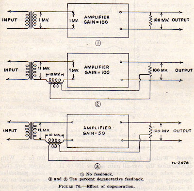
Figure 1 shows an amplifier that increases the input voltage by a factor of 100. In Figure 2, 10 percent of the output voltage is fed back – out of phase – to the input. Now, when trying to understand feedback amps, you can find yourself trying to figure out how changes to the input produce changes to the output, which in turn produce changes at the input, etc. Like the amplifier you are trying to understand, you become like a dog chasing his tail! TM 11-455 elegantly breaks this cycle. It has us think this way: Assuming we maintain 100 mV at the output, with 10% fed back, how much of an input signal will we need? Well, the amplifier itself still amplifies voltage by 100. So we still need a net voltage of 1 mV at the input. So now we need a signal voltage of 11 mV to produce the 100 mV output (Figure 2). The feedback cancels 10 mV, putting 1 mV on the input. Negative feedback reduces gain.

How does negative feedback reduce the impact of variations in the gain characteristics of the individual devices? Without feedback, if we substituted our 100X amplifier for a device with a gain of only 50, our 1 mV input would produce only 50 mV out, possibly playing havoc with our overall design. We’d need an input of 2 mV -- a doubling of the input voltage -- to make up for the variation, to get our desired 100 mV output. But look at the situation with feedback (Figure 3). We still assume 100 mV at the output, and 10 percent negative feedback. But now, even though device gain has dropped from 100 to 50, we only need an increase in signal input from 11 mV to 12mV. With this feedback arrangement, if we kept the input signal level at 11mV, and then used a transistor that happened to have only HALF the voltage gain of the original device, the output voltage would drop only to around 92 mV, a drop of about 9% -- not the 50% drop we saw in the circuit without feedback. Negative feedback reduces the impact of gain variations from device to device. It makes our amplifier stages more “beta independent.” Negative feedback reduces the impact of gain variations from device to device. It makes our amplifier stages more “beta independent.” Our thanks to the War Department!

Sunday, January 18, 2009

SolderSmoke 99

SolderSmoke99.mp3

January 18, 2009
Epiphany in Rome -- La Befana brings two Gerbils (Dot and Dash)
Ice skating near (but not on!)the Tiber
QRSS: Eldon's beacon spotted. 723 miles with 15 millwatts
QRSS Calibration Problem: My proposed solution
A Tale of Two BENELUX Grabbers: ON5EX and PA1SDB
Watching VK2ZAY cross Tasman Sea. Watching G6AVK reach VK6DI
Inspiration from old SPRATs: From PA3BHK and W7ZOI
Book Review: "Empire of the Air" (Good bios, but author Knack-less)
AA1TJ's CFL revolution reaches Cuba. Now a CFL receiver.
AA1TJ's "Reggie" converts all sigs to QRP!
Several new videos on the Blog (from WA7MLH, N0TU, KD1JV)
MAILBAG: Ragav VU3VWR has Knack since 9th grade. Wants to QRSS in VU
Nick M0NJP likes show, getting used to the voice, Amazon UK instructions
Bryan VK3HXR has eeePC running Ubuntu
Paolo IK1ZYW has external keypad chips for FT-817 (available at cost)
Jim AL7RV's wife thought SolderSmoke gave him a fit. Agrees on 1)design 2)build
Wes W7ZOI on feedback circuits
Joe Rocci has an LtSpice model for the NE602
Gerri EI8DRB asks if he should buy a Drake 2-B (Uh... YES!)
Steve "Snort Rosin" Smith : SMT paste lacks bouquet of 60/40 multi-core
Chris KC2LFI prescribes 3500 Hz notch for sibilant SS problem (advice followed)

Saturday, January 17, 2009

Homebrew Rigs from WA7MLH


Jeff Damm, WA7MLH, was the builder of some of the rigs that appear in "Solid State Design for the Radio Amateur" His DSB/CW Direct Conversion receiver for 75 meters is in that book. Last January, Jeff put together a video that describes some of the rigs and pieces of test gear currently in his shack. Beautiful stuff.

Thursday, January 15, 2009

International Year of Astronomy -- 2009


Hey, the signals are electromagnetic. They are very QRP. And the receivers (well, at least the "amplifiers") are often homebrew. It's 400 years since Galileo spotted Jupiter's moons. To commemorate this, we have IYA2009. The organizers are developing a program to allow people to build their own simple telescopes, and are encouraging those who already have 'scopes to get out and let their neighbors take a look at the wonders of the universe. We did a bit of this "sidewalk astronomy" in London. We'll do our part for IYA2009 by taking our 6 inch Dobsonian out into the piazza here in Trastevere. Check out the project web site:
http://www.astronomy2009.org/globalprojects/cornerstones/galileoscope/

RADIO PIONEER: HAROLD BEVERAGE

I came across this interview with Harold Beverage, inventor of (among many other things) of the antenna that bears his name. I liked his description of the personalities and design methods of some the people he worked with (including Ernst Alexanderson).
Take a look: Beverage IEEE interview

Wednesday, January 14, 2009

Eldon's Beacon: GRABBED!

Last week we put out an all points bulletin for the new QRSS beacon of OM Eldon (scroll down a bit). Yesterday the signal was captured by Stu. Distance covered: 723 miles. Eldon's power out: 15 milliwatts. That's correct: fifteen milliwatts (Eldon had earlier calculated 150 milliwatts, but this turned out to be incorrect). Above is Stu's screen shot -- you can see Eldon's FSK signal: WAOUWH (read along the top of the square wave) at around 10140050 Hz.

Here is their e-mail exchange:

Re: Is this your QRSS beacon?
Tuesday, January 13, 2009 6:17 PM
From:
"Eldon"
To:
"Stu"
Thanks Stu, and thanks to Bill Meara and SolderSmoke.com
This is my my FIRST confirmed QRSS report from my first QRP rig, it is about 150mw into a North South 6 foot Loop about 6 feet AGL.
You represent it on about the freq that I think it is - without too much calibration on my part.
See: http://qth.map.googlepages.com/?qth=CN97BV43TU&from=CM87vk
Is your Grabber online?
Thanks for the report.
Regards, Eldon Brown - WA0UWH
Don't let the Zero land call fool you, I got it many year ago while in the Navy stationed at Denver, now located in Seven land near Seattle.
eldonb@ebcon.com

On Tue, Jan 13, 2009 at 12:39 PM, Stu wrote:
Eldon,
Copied the following screen shot on 30m today a few minutes ago – I think the FSK is your callsign – WA0UWH?
Copied with Spectrum Lab in CM87vk – TS-B2000 with 160m inverted L plus antenna tuner to load up on 30m
73's
Stu
Designer: Douglas Bowman | Dimodifikasi oleh Abdul Munir Original Posting Rounders 3 Column