


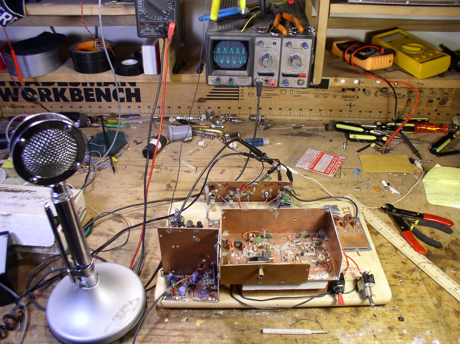
 There it is, sans kick panel. You can see the breadboard (a real one!) on which it is built. The box in the center has the oscillator circuitry (currently on 75 meters, but subject to change); the box is elevated a few inches by two pieces of wood -- I do this so that the frequency control will be a comfortable distance from the table! HB-ergonomics! The AF (mic) amp is in the lower left (just a 741 op amp). You can see the adjustment pot of the balanced modulator behind the mic amp. The low pass filter of the PA is visible on the right (rest easy Steve Smith!). The switch on the right is T/R. The red switch is "spot" (or in the UK "net").
 I thought I was having some trouble with RF getting into the mic amp. The audio out from the mic amp looks a bit distored when I have the oscillator and PA circuits fired up. I worked on it for a while, beefing up the decoupling on the 12 volt lines, but that didn't change things. I've decided not to worry about it, because the output signal from the final looks clean, and the signal sounds good on my trusty Drake 2-B. It may have been a test gear problem -- the 'scope probe may have been picking up some RF and may have been uglying up the AF wave form.
Our book: "SolderSmoke -- Global Adventures in Wireless Electronics"http://soldersmoke.com/book.htmOur coffee mugs, T-Shirts, bumper stickers: http://www.cafepress.com/SolderSmokeOur Book Store: http://astore.amazon.com/contracross-20


