Podcasting since 2005! Listen to Latest SolderSmoke

Sunday, December 15, 2013

20/40 BITX Build Update #1: VFO Success


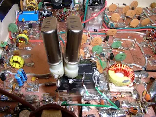
I've started construction on my second BITX transceiver, this one for 20 and 40 meters.  As with the previous rig, I decided to take the VFO first, but this time I pledged not to surrender, not to wimp out with a VXO or (worse!) a DDS.   No, this time it would be a real LC VFO.

I took seriously all the admonitions in the tech literature about the fickle permeability of ferrite and iron powder, so this time I used an old-fashioned air-core coil.  It is wound around a cardboard tube.  The tube was previously the bottom portion of a coat-hanger from the dry cleaner.  I wound 40 or so turns on this core, then measured the inductance:  5.6 uH -- that looked about right.

For the oscillator stage I used a Colpitts circuit very similar to the one in the original BITX schematic (but I am hoping I won't need the varactor diode fine tune mechanism).   I had on hand a nice Heathkit 19-146 pf variable cap with an internal 4:1 reduction drive.  Not wanting to pluck rotor places out of this beautiful part, I had to calculate the series capacitance that would yield a frequency spread of about 175 kHz.  It turned out to be 40 pf.  Then I had to figure out how much capacitance to put in parallel with the variable.  Well, it all ended up like this:


There was a bit of trial and error in the process of getting the VFO to cover the desired range.  A big help in all this was an on-line reactance calculator.  I found this one to be very useful:
  
http://www.1728.org/resfreq.htm

I found that the VFO is more stable if I reduce the voltage from 12 volts down to about 8.  Also, I found that when evaluating the stability, it is better (psychologically!) just to use a stable superhet receiver instead of the frequency counter.  The counter may appear to be jumping around a lot, especially if the signal you are monitoring is not very strong.  Just listening to it at zero beat on the superhet is very reassuring.

I followed the Colpitts oscillator with the FET buffer and two stage BJT amplifiers from page 50 of Doug DeMaw's QRP Notebook (page 50).  I now have the requisite 7 dbm signal.  And it appears to be quite stable. 

I plan using this with an 11 MHz IF, with the VFO running at around 3.875--3.700 for 40 meters and 3.175 -- 3.355 for 20.   I plan to use a small relay to switch in some additional capacitance to move the VFO down to the range for 20 meters.


Our book: "SolderSmoke -- Global Adventures in Wireless Electronics" http://soldersmoke.com/book.htm Our coffee mugs, T-Shirts, bumper stickers: http://www.cafepress.com/SolderSmoke Our Book Store: http://astore.amazon.com/contracross-20

Saturday, December 14, 2013

University of Twente's Online Receiver


Wow, I played with this on-line SDR receiver a few years ago and thought it was fantastic.   It is now even better.  I'm sitting here listening to 40 meters in the Netherlands.  Great stuff.   Check it out.  It is really amazing:

http://websdr.ewi.utwente.nl:8901/

Thanks to Bob, KD4EBM for letting me know about the updates. 

Our book: "SolderSmoke -- Global Adventures in Wireless Electronics" http://soldersmoke.com/book.htm Our coffee mugs, T-Shirts, bumper stickers: http://www.cafepress.com/SolderSmoke Our Book Store: http://astore.amazon.com/contracross-20

Friday, December 13, 2013

Circular Polarity and The Water Wheel in Dale's Moonbounce Amplifier

Bill:
 
I'll attach some pix of the feedhorn and LNA for you.

The importance of circular  feeds is that as a linear wave passes through the ionosphere, it undergoes Faraday rotation. So it may arrive at  the station you are talking to having been twisted 90 degrees. This  is a slow progressing process and  on  all bands except 23cM, may cause EU for example to be locked out for hours at a time for linear stations.

With circular polarity, Faraday is a non issue. The feedhorn almost all of us use is a VE4MA that has separate TX and RX probes. The circular polarity is synthesized as the linear wave propagates down the circular waveguide and encounters sets of  capacity stubs. The exact opposite occurs for waves entering the waveguide. The result is we get CW and CCW without having to use any relays (loss) and phasing  lines (loss).

My LNA has a noise figure of under 0.24dB and uniquely connects to a protection relay with no cable or adapters (loss).

The position of the feedhorn and its scalar ring is tediously adjusted by measuring the difference between sun noise and cold sky. W4SC developed a very accurate and repeatable process that uses an SDR RX for this.

I use  a modified C band satellite drive system known as a polar mount so I only need one motor drive to track the moon.

Anyway, hearing my own echoes off the moon was and still is the highlight of my amateur career. 
 
The photos are the feedhorn + LNA, My first water cooled 500W  tube amp, my previous 400W solid state amp (mounts right at the dish). My current design is 600W solid state and will also mount at the dish.

BTW, that little circle in the middle of the tube amp is a paddle wheel that turns as long as water is flowing. A tachometer on the wheel sounds an alarm and shuts down plate voltages   should the wheel stop turning.

I'll keep  you up to date on my BB RX progress- thank you again Bill.

Dale W4OP


Our book: "SolderSmoke -- Global Adventures in Wireless Electronics" http://soldersmoke.com/book.htm Our coffee mugs, T-Shirts, bumper stickers: http://www.cafepress.com/SolderSmoke Our Book Store: http://astore.amazon.com/contracross-20

Wednesday, December 11, 2013

The NASA Juno Fly-by "Hams say HI to Juno" Video (very nice)


Our book: "SolderSmoke -- Global Adventures in Wireless Electronics" http://soldersmoke.com/book.htm Our coffee mugs, T-Shirts, bumper stickers: http://www.cafepress.com/SolderSmoke Our Book Store: http://astore.amazon.com/contracross-20

Tuesday, December 10, 2013

The QRP Mojo Ceremony


More from Lobstercon (from N2HTT): 
 http://n2htt.net/2013/11/24/there-are-lobsters-in-the-woods/
And thanks to Pete, VE2XPL, for alerting me to all this. 

Our book: "SolderSmoke -- Global Adventures in Wireless Electronics" http://soldersmoke.com/book.htm Our coffee mugs, T-Shirts, bumper stickers: http://www.cafepress.com/SolderSmoke Our Book Store: http://astore.amazon.com/contracross-20

Sunday, December 8, 2013

Need help with part construction...

Please take a look and see if you can help me figure out how to make this thing.  The diagram is eschpecially illuminating.
 
 
THE DIE-CAST DROP-FORGED PLASTIC

TRICHOTOMETRIC INDICATOR-SUPPORT
          Inquiries concerning the mounting of the Trichotometric Indicator
          Support indicate that some difficulty is being experienced with the
          brackets which attach the support. As an aid toward fabricating the
          support brackets, the accompanying illustration is provided to show
          the type of material as well as the dimensional data needed. It will
          be noted that in attaching the bracket to the support a special ambi-
          melical hexnut is used. The application of this nut is unique in that
          any attempt to remove it in the conventional manner only tightens it.
          Because of this design, the nut must be fully screwed on before it can
          be screwed off.


DRAWN BY
FRED SPOON
SCALE ¼”=1 MILE
NO. 43906
FILE – BAR NONE

 Thanks to ZL2DEX for bringing this to our attention.


Our book: "SolderSmoke -- Global Adventures in Wireless Electronics" http://soldersmoke.com/book.htm Our coffee mugs, T-Shirts, bumper stickers: http://www.cafepress.com/SolderSmoke Our Book Store: http://astore.amazon.com/contracross-20

On the Wavelength of Santa's Sled (with a nod to FA Wilson)

About a year ago, David, M0VTG, was reading "From Atoms to Amperes" by FA Wilson.   His thoughts turned to a seasonal application of Wilson's lessons....  Thanks David! 

WAVELENGTH OF SANTA AND HIS SLEIGH

We're going to need to know the following:

Total mass of the sleigh, reindeer, Santa and his presents, and the speed at which the sleigh travels. Assuming that the sleigh travels relatively close to the surface of the earth, the mass can be regarded as the same as the weight. Now assume each reindeer weighs 100 kg. Traditionally there are nine of them so total mass of the reindeer is 900kg. Say the sleigh also weighs 500kg and Santa and his presents weigh 400kg; then the total mass is 1800kg. To get round all the children who believe in him in one night would mean him travelling at a speed of say 1000kph (277.8 m/s). (Note that scientific notation for numbers used is that used on some calculators)

So mass (m) is 1800kg
velocity (v) is 1000kph (notice the not so subtle change from a scalar quantity to a vector quantity).

Max Plank came up with a formula: E = hf relates Energy to frequency using h (Plank's constant = 6.626 E-34 Joule seconds).

Albert Einstien (as everyone knows) says that E = mc2 (where c is the velocity of light).

So it follows that hf = mc2 and therefore, m = hf/c2.

The momentum of a photon (p) is defined as mass x velocity or p = mv and as every radio amateur knows, wavelength (λ) is the velocity of light divided by frequency or λ = c/f (or f/c = 1/ λ).

So mv = hf/c2 x c (velocity of a photon is c don't forget); so p = hf/c

Since f/c =1/ λ, then p = h/λ i.e. λ =h/p

Also since p = mv then λ = h/mv (This expression is known as the de Broglie wavelength - Louis Victor de Broglie)

Notice that the velocity of light does not directly feature is the expression. We can, therefore use it the calculate the wavelength of anything!

So the wavelength of Santa's sleigh is Plank's constant divided by the mass times the velocity or

λ = 6.626 E-34 J s / (1800 kg x 277.8 m/s) which equals 1.325 E-39 m - an unbelievably small number! Make up you own mass and velocity for the sleigh if like.


I defy NORAD to track such a short wavelength.


Our book: "SolderSmoke -- Global Adventures in Wireless Electronics" http://soldersmoke.com/book.htm Our coffee mugs, T-Shirts, bumper stickers: http://www.cafepress.com/SolderSmoke Our Book Store: http://astore.amazon.com/contracross-20

Saturday, December 7, 2013

"Snort Rosin" Seal of Approval for "Ferrari-esque" Italian Wire Cutters

Hakko CHP-170 Micro Clean Cutter, 16 Gauge Maximum Cutting Capacity
And now for something (almost) completely different.  Rarely have wire cutters been described in such, well, almost erotic terms.  This definitely seems like the stocking-stuffer of the year for the SolderSmoke in-crowd.  And to think that I was pleased with a pair of $3.99 hemostats that I got from Amazon.

Hi Bill,

It's always nice to find something high-quality and inexpensive and today it happened to me so I thought I'd share my good fortune.

Having been in the professional radio repair business for 40 years (retired 2012), I very much appreciate quality hand tools.  On my bench at home I have an expensive pair of Lindstrom wire cutters but in the field I generally resorted to cheaper, not so high-quality tools (in case of inadvertent loss).  The problem at home is it seems like every time I need to grab my Lindstroms, they're not where I'm at so I've been on the lookout for a spare pair or two of quality cutters.  Well, today in the Fry's Electronic newspaper flyer I saw an ad. for Hakko brand wire cutters on sale for $2.99, regularly $4.99, a 40% saving.  Me being, shall we say, "thrifty",  this immediately got my attention.  I know Hakko markets some very good soldering related equipment, however until today I had no experience with their line of hand tools. 

So, between some appointments this morning I stopped at our local Fry's store and checked out the cutters.  I was expecting to find something typically cheap and made in China so imagine my surprise at discovering they are made in Italy!  The part # of this particular tool is CHP-170 and is mfg. by the CHP Tools division of Hakko.  The hand grips are palm-fitting and very comfortable with thumb and forefinger rests at the top of each for tool manipulation.  The design is what I would call "Ferrari-esque"; bright red with black accents.  Very pleasing to the eye.  Turns out that The metal parts are  high grade tool steel and Parkerized for low reflectivity and high wear and corrosion resistance.  What impressed me the most is the cutting surfaces; they mate perfectly.  So many inexpensive cutters have lousy mating surfaces, these don't.  With the cutting edges 'closed', shining a high-intensity light on one side results in -no- light 'leaking' by the mated edges.  That's first-class machining! 

IMO, even at the typical price of $5 or so, these cutters are a bargain, especially considering the quality (how does one say, "it is very good!" in Italian?).  So, if you or anyone you know is in the market for some great wire cutters, tell them that the Hakko CHP-170 has the "Snort Rosin" seal of approval, HA!

73.......Steve Smith WB6TNL

 http://www.amazon.com/Hakko-CHP-170-Maximum-Cutting-Capacity/dp/B00FZPDG1K

Our book: "SolderSmoke -- Global Adventures in Wireless Electronics" http://soldersmoke.com/book.htm Our coffee mugs, T-Shirts, bumper stickers: http://www.cafepress.com/SolderSmoke Our Book Store: http://astore.amazon.com/contracross-20

Friday, December 6, 2013

"The Amateur Scientist" by C.L. Stong (FREE!)

This great book is available on-line:   You guys will really like it:

https://archive.org/details/TheAmateurScientist


Our book: "SolderSmoke -- Global Adventures in Wireless Electronics" http://soldersmoke.com/book.htm Our coffee mugs, T-Shirts, bumper stickers: http://www.cafepress.com/SolderSmoke Our Book Store: http://astore.amazon.com/contracross-20

Renaissance Man Illustrator for Scientific American


C.L. Stong wrote the "Amateur Scientist" column for Scientific American for many years.  When I was a boy, my mom saved up to buy me the anthology of Strong's columns.  It had a big impression on me -- I still have a copy on my shelf.  I never gave much thought to the illustrations, but I now realize that they were responsible for much of the impact that that book had on me.  The cloud chamber drawing was one of my favorites.  Note the use of peanut-butter jars.  Yea!  
 
This morning an article on the Maker blog focused on the genius who did all those wonderful drawings:  Roger Hayward (I wonder if there is any relation to Wes and Roger -- all three are from Oregon and all three are technical geniuses.)
 
I found this very nice web site about Roger Hayward: http://scarc.library.oregonstate.edu/omeka/exhibits/show/hayward/introduction/introduction/
There are great illustrations in many places.  For the Scientific American drawings go to the 1960s section.

And check out this one:


From: http://scarc.library.oregonstate.edu/omeka/items/show/4456

 
Our book: "SolderSmoke -- Global Adventures in Wireless Electronics" http://soldersmoke.com/book.htm Our coffee mugs, T-Shirts, bumper stickers: http://www.cafepress.com/SolderSmoke Our Book Store: http://astore.amazon.com/contracross-20

Thursday, December 5, 2013

W4OP -- Earth-Moon-Earth and Another Barebones Superhet


Years ago I bought a Barebones Superhet from Dale Parfitt on E-bay.  Several years after that, having forgotten who I bought it from, I was asking questions about how to get it working on 17 meters.  Dale jumped in with some very helpful e-mails.  It took us both a while to realize that I was working on the receiver that he had built.  Dale is active in a really wide range of ham radio activities, everything from QRP to EME.  Check out his homebrew projects here (I really like his Solid State Drake 2-B!) http://www.parelectronics.com/par-homebrew-projects.php 
And his vintage projects here: http://www.parelectronics.com/vintage-radio-restoration.php
And here's what Dale has been doing with the Moon (that's his 15 foot dish in the picture): 
 
Hi Bill,
 
I thought of you today when I won a Bare Bones Barbados RX on eBay for $5. I am going to team it with a DDS VFO and a matching TX.Some parts are apparently missing, but i have a huge junk box and also know how to order from Mouser should the junk box fail me.
 
 
Right now I am putting my solid state 650W 1296MHz EME amp , Power Supply, meters etc. in its waterproof cabinet so I can mount it right at the dish and not incur any feedline losses.
 
1296 is probably the best EME band. Power is getting easier and easier to acquire (although solid state is around $5/watt), dishes are fairly easy to acquire or build and  perhaps most importantly, we all use circular polarity feeds with no relays/hybrids. Activity weekend can sound like 20M, with a number of stations just ragchewing on CW and SSB.
 
73,
Dale W4OP
for PAR Electronics, Inc.
http://www.parelectronics.com


Our book: "SolderSmoke -- Global Adventures in Wireless Electronics" http://soldersmoke.com/book.htm Our coffee mugs, T-Shirts, bumper stickers: http://www.cafepress.com/SolderSmoke Our Book Store: http://astore.amazon.com/contracross-20

Wednesday, December 4, 2013

Thermitron (Tube, Valve) Op-Amps


It is kind of appealing.  I like it better than the 741.  This one you can take apart and see how it works.   Thanks Rogier!

Our book: "SolderSmoke -- Global Adventures in Wireless Electronics" http://soldersmoke.com/book.htm Our coffee mugs, T-Shirts, bumper stickers: http://www.cafepress.com/SolderSmoke Our Book Store: http://astore.amazon.com/contracross-20

Monday, December 2, 2013

On the suffering of Geeks. Indeed, we suffer...

M I a Geek :D

Our book: "SolderSmoke -- Global Adventures in Wireless Electronics" http://soldersmoke.com/book.htm Our coffee mugs, T-Shirts, bumper stickers: http://www.cafepress.com/SolderSmoke Our Book Store: http://astore.amazon.com/contracross-20

Sunday, December 1, 2013

11 MHz IF for new BITX 20/40 Dual Bander? Also: Cabinetry and Socketry

I am gathering parts and ideas for a BITX dual bander (20 and 40 meters).  I know Farhan used a 10 MHz filter for his "Simple SSB Transceiver."  But I was thinking of going a bit higher, to 11 MHz. This would allow me to run the VFO from 3.175 to 3.355 for 20 meters, and 3.695 to 3.875 for 40 meters. I'm hoping that I can do this with one single VFO (Farhan used two VFOs), perhaps with a reed relay switching in some additional capacitance for the other band. I'll also follow Farhan's lead and switch the Low-Pass and Band-Pass filters with DPDT relays.

I set up a simple spread sheet and looked at the VFO harmonics to see if any fell within the desired tuning ranges.  That looks OK. I have not looked at mixing products between VFO and BFO.  What do you folks think?   Would the 11 MHz IF for these bands work?  Or are there evil birdies lurking in my future?

I've gone ahead and bought another wood box for the new rig (I didn't even have to suffer through a second visit to the crafts store -- they are available on Amazon).  I also got a roll of copper sheeting at Home Depot.  This time I will prepare the box first, lining the inside with copper and preparing all the "socketry" (George Dobbs' word) before putting the PC board in.
 
Our book: "SolderSmoke -- Global Adventures in Wireless Electronics" http://soldersmoke.com/book.htm Our coffee mugs, T-Shirts, bumper stickers: http://www.cafepress.com/SolderSmoke Our Book Store: http://astore.amazon.com/contracross-20

Friday, November 29, 2013

First Pictures of the Far Side of the Moon (1959!)


On October 7, 1959, the Soviets sent an "automatic interplanetary station" to the moon.  This, in itself, was an amazing achievement.  Even more amazing is how they managed -- using 1950s technology -- to photograph the far side of the moon and get the images back to the earth. 

The Soviet document on the Harvard site (below) says that the transmitter put out "a few watts" and used semiconductors.  There appears, however, to have been at least one vacuum tube aboard (the cathode ray tube used to scan the chemically developed photo negatives).  Frequency modulated analog video similar to FAX) was used to send the data.

http://articles.adsabs.harvard.edu//full/1962IAUS...14....7L/0000007.000.html

From Wikipedia:

Luna-3 was the first successful three-axis stabilized spacecraft. During most of the mission, the spacecraft was spin stabilized, but for photography of the Moon, the spacecraft oriented one axis toward the Sun and then a photocell was used to detect the Moon and orient the cameras towards it. Detection of the Moon signaled the camera cover to open and the photography sequence to start automatically. The images alternated between both cameras during the sequence. After photography was complete, the film was moved to an on-board processor where it was developed, fixed, and dried. Commands from the Earth were then given to move the film into a scanner where a spot produced by a cathode ray tube was projected through the film onto a photoelectric multiplier. The spot was scanned across the film and the photomultiplier converted the intensity of the light passing through the film into an electric signal which was transmitted to the Earth (via frequency-modulated analog video, similar to a facsimile). A frame could be scanned with a resolution of 1000 (horizontal) lines and the transmission could be done at a slow-scan television rate at large distances from the Earth and a faster rate at closer ranges.
The camera took 29 pictures over 40 minutes on 7 October 1959, from 03:30 UT to 04:10 UT at distances ranging from 63,500 km to 66,700 km above the surface, covering 70% of the lunar far side. Seventeen (some say twelve) of these frames were successfully transmitted back to the Earth, and six were published (frames numbered 26, 28, 29, 31, 32, and 35). They were mankind's first views of the far hemisphere of the Moon.

More info: http://www.svengrahn.pp.se/trackind/luna3/Luna3story.html#Film


Our book: "SolderSmoke -- Global Adventures in Wireless Electronics" http://soldersmoke.com/book.htm Our coffee mugs, T-Shirts, bumper stickers: http://www.cafepress.com/SolderSmoke Our Book Store: http://astore.amazon.com/contracross-20

Monday, November 25, 2013

A British Bicycle (and Workshops)


Experiments in Speed from SpindleProductions on Vimeo.


Our book: "SolderSmoke -- Global Adventures in Wireless Electronics" http://soldersmoke.com/book.htm Our coffee mugs, T-Shirts, bumper stickers: http://www.cafepress.com/SolderSmoke Our Book Store: http://astore.amazon.com/contracross-20
Thursday, November 21, 2013

BITX Build Update #20 -- Switchable Crystals, South Africa QSO


I got tired of popping the hood and manually changing my VXO crystals.  First I tried to switch the rocks using a rotary switch on the front panel, but I think the leads were too long and the output was kind of squirrely.   So I dug around in the junk box and found a 12 volt double pole double throw relay.  I put the crystal sockets across the two poles and ran leads from the armature terminals to the crystal terminals. I use the rotary switch to activate the relay.  I cover about 41 kHz of the 17 meter band with the two crystals. 

17 meters has been in great shape.  On November 16 I had a very nice contact with Syd, ZS1TMJ in Glenwilliam, South Africa.  That's about 8000 miles on 5 watts SSB.   

Our book: "SolderSmoke -- Global Adventures in Wireless Electronics" http://soldersmoke.com/book.htm Our coffee mugs, T-Shirts, bumper stickers: http://www.cafepress.com/SolderSmoke Our Book Store: http://astore.amazon.com/contracross-20

Wednesday, November 20, 2013

Naval Gun Turret as EME Dish Mount (VIDEOS)


Hack-A-Day ran a story on EME pioneer Zoltan Bay.  In the comments section someone posted this memorable video about a moonbounce station in Central Kansas.  Wow.  Putting using naval gun as an AZ-EL rotor for the dish is really thinking outside the box.   Then deciding to put the whole thing atop another tower...  Great stuff.


Here is another moonbounce video. VE2ZAZ was using a smaller antenna (!) and JT65. FB.

Our book: "SolderSmoke -- Global Adventures in Wireless Electronics" http://soldersmoke.com/book.htm Our coffee mugs, T-Shirts, bumper stickers: http://www.cafepress.com/SolderSmoke Our Book Store: http://astore.amazon.com/contracross-20

Sunday, November 17, 2013

M0XPD's Digital Analog BITX -- Best of Both Worlds


Paul, M0XPD, has built a very interesting version of the BITX rig.  His is on 40 meters.  It features plug in bandpass and IF filters (great idea!) and uses DDS technology for both the BFO and VFO stages.  Good going Paul!  More details here:
http://m0xpd.blogspot.co.uk/2013/11/rising-to-challenge.html

Our book: "SolderSmoke -- Global Adventures in Wireless Electronics" http://soldersmoke.com/book.htm Our coffee mugs, T-Shirts, bumper stickers: http://www.cafepress.com/SolderSmoke Our Book Store: http://astore.amazon.com/contracross-20

Friday, November 15, 2013

Standard Computer Crystals for 17 Meter SSB VXO and IF Filter


Pete Juliano, N6QW, is an electronic  genius.  The ideas in his SPRAT article will be of great use to all those who share in Doug DeMaw's devotion to VXOs and reluctance to spend money.  I'm really tempted to go back and re-do my BITX using Pete's 11.52 MHz computer crystal super-VXO and 4.9152 IF (I could then take my expensive 23.1 MHz crystals and put them back in my Doug DeMaw Barebones Superhet).  I also like Pete's DPDT reed relay crystal switcher too.  Three cheers for Pete Juliano, Doug DeMaw, and SPRAT!  And thanks to WB9FLW for reminding us of Pete's articles.

Hi Bill,
 
Your BITX17 really has me fired up! I came across an interested Super VXO by Pete N6QW for use on 17 Meters.

He uses standard computer xtals (4.9152 MHz for the IF) and (3 - 11.520 MHz freq doubled in the VXO)

This gets you on 18.120 to 18.150 using these two standard xtals.

See Link Below:
 
http://www.jessystems.com/SPRAT%20Article.pdf

http://www.jessystems.com/Images/23%20MHz%20VXO.jpg


Thanks for all your efforts they are much appreciated!!

Best Wishes,
Pete WB9FLW


Our book: "SolderSmoke -- Global Adventures in Wireless Electronics" http://soldersmoke.com/book.htm Our coffee mugs, T-Shirts, bumper stickers: http://www.cafepress.com/SolderSmoke Our Book Store: http://astore.amazon.com/contracross-20
Designer: Douglas Bowman | Dimodifikasi oleh Abdul Munir Original Posting Rounders 3 Column