Just go to http://soldersmoke.com. On that archive page, just click on the blue hyperlinks and your audio player should play that episode.
http://soldersmoke.com
Oh man, I share this with much trepidation because the last time I posted something about the work of Mike KG7TR, Pete N6QW said he felt like putting all of his own work in the dumpster, so much better was the artistry of KG7TR. This receiver is so cool and so well-done that we now might have to post a guard outside the N6QW shack -- heck Mike even has an Arduino Uno and an Si5351 in there! Don't do it Pete!
I was led to this magnificent receiver by the very humble 6U8 tube. Scott WA9WFA and I have been learning (mostly from Grayson KJ7UM) that the much used and sometimes loved 6U8s (three of them in our "Mates for the Mighty Midget") might be a bit long in the tooth, old even by Thermatron standards. I was worried when I remembered that my Drake 2-B has a 6U8 in it -- V2, the first mixer. So I Googled for more info and was led to this amazing receiver, a 2018 creation by KG7TR. How did we NOT see this for almost four years?
As for the 6U8s, well Grayson says the tube has been getting something of a bum rap. And KG7TR has two of them in this receiver, so I will obviously have to give the 6U8 another chance.
--------------------
I didn't know that Lew McCoy had his own crystal and crystal filter company:
In SolderSmoke Podcast #234, I said that I was scrutinizing the filter from the Swan 240 that I had picked up around 1994 in the Dominican Republic. I cannibalized it out in the Azores in the early 2000s and used the parts to build -- among other things -- my first SSB transmitter. I never really focused much attention on the filter that I pulled out of that old rig -- I was just happy that it seemed to work. But I am now older and wiser, and I have some test gear that lets me look at the passband of that filter.
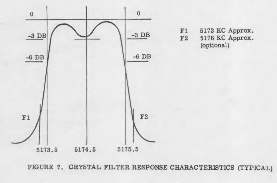
First, take a look at what it is supposed to look like. This is from the manual. Yikes! That passband looks far from flat. I can almost hear homebrewers around the world shrieking in horror and disgust.
Above is a description of the filter, and the schematic, again from the manual.
Here is what my extracted and somewhat re-built filter looked like in my NanoVNA (more shrieking!). The dip in the passband is a lot worse here -- it looks like 10 db vs. 3 db in the manual. This is probably because I'm not even attempting any impedance matching on the filter -- it is just seeing the 50 ohms in and out of the NanoVNA.
Here is my 2002 attempt to rebuild the filter and put it in my SSB transmitter, along with my more recent attempt to flatten the passband. I no longer had the adjustable coil L8, so I made my own coil based on guidance from Ben Vester W3TLN's January 1959 QST article on "Surplus-Crystal High-Frequency Filters." (Ben had an early influence on Pete Juliano's tube-rig designs.) In the picture above I have 1k pots between the filter and the input and the output of the NanoVNA, as described by Nick M0NTV.
Adjusting the 1 k pots, I could smooth out the passband quite a bit. Measuring the pots and adding the 50 ohms of the NanoVNA, it looks to me like this filter is smoother with about 280 ohms at the input and output. I may build two matching networks or some transformers. Some TIAs may also be needed.
(Why the T/R diodes in the BITX 20 amplifiers?) National Receiver.
Bill's Bench Farhan's Talk to RSGB got me thinking of VHF 2 meter AM. 2 meter Benton Harbor lunchbox madness. SuperRegens Super Strange. I broke my Maplin AF Sig Gen in the process. Fixed it. Playing with MMMRX again. Put in 6 kHz ceramic filter. Sounds great SSB and AM. Swept IF with noise, TinySA, and NanoVNA. Need better noise gen. Mod to listen with TinySA (on blog). Thinking of 17 meter /12 meter Dual-Bander IF around 21.4, VFO around 3.41 Mhz. Thoughts? Sweeping double half lattice filter from Swan 240. UGLY.
MAILBAG: --- ROOTS OF MAILBAG: Radio Moscow, Havana Cuba, HCJB, others. -- Thomas K4SWL of the SWL Post: Could have been worse! Stairbag?
-- MY NOVICE LOG -- Heard back from ex-WN2RTH ex-WN2FLK ex-WB2RKK. -- Drew N7DA worked Wes W7ZOI in Sweepstakes. FB. -- Peter VK2EMU The movie Frequency and the Magic of Heathkits. Good, but not that good! -- Thomas KK6AHT! Our old friend. Minima! Now has a young son! FB -- Chuck WA7ZZE Saw QST profile. Sympathizes with Two-er trouble. -- Tim M0CZP. Spell corrector. Vatican Diodes. Infallible! -- Ramakrishnan VU3RDD Working on a NORCAL and a noise cancellation arrangement. -- Skip NC9O said I was 40 Hz off on 17. But he had a reason to KNOW! -- Steve K9NVD Glad he's a listener. -- Bob KY3R Novice Nostalgia. Should he use 75 watt bulb for dummy load? Yes! -- Todd K7TFC Video about why solder smoke goes into the face. -- Anthony VU3JVX Homebrew Antuino. I ask for help in moving freq to 450 kHz. -- Jack NG2E Building Pete's DC RX. -- Scott WA9WFA HBR-13 and MMMRX. -- Stephen 2E0FXZ also got a FT-101 VFO. -- Bob K7ZB on the air with 56 mW and a big antenna. -- Dean AC9JQ Retired. -- Allan WA9IRS Right to Repair update. -- Farhan Invited us to Lamakaan ARC, Dec 11 or 12. Will be on QO100 Satellite Live!
-- Many suggestions about my Apollo 11 Time Capsule. Still looking for ideas.
Happy Thanksgiving to all who celebrate this holiday!
K9YA Telegraph ran (on Facebook) this ad from 1954. It provides an interesting view of where phone operations were in that year. Note that Dale was so intent on selling SSB gear that they were willing to make on-the-air schedules to demonstrate SSB superiority.
Dale claims that with SSB you could have TWO roundtable QSOs on the same frequency, with one group on USB and the other on LSB. I think this assumes really great opposite sideband rejection in the transmitters, and excellent selectivity in the receivers. That might have been a bit of a stretch. But the assumption here was that hams could use USB or LSB -- no rigid adherence to the USB/LSB convention. And the ad seems to focus on the 75 meter band which was seen as the most important phone band at that time.
Dale was selling Collins mechanical filters for 55 dollars. That is the 1954 equivalent of $566 dollars today. No wonder the phasing method was so popular. Note that they were selling Central Electronics phasing rigs right next to the ad for the Collins filters.
I like the graph showing opposite sideband rejection with the Sideband Slicer. Note that the selected sideband was referred to as the "exalted" sideband. All Hail the Single Sideband!
The cover caught my eye. Thanks to the K9YA Telegraph for posting it. I think it captures the allure of radio that most of us felt when we were kids of this age.
Fortunately this 1922 book is available for free download:
It is all about radiotelephone. They are phone guys. Just like us.
And they were homebrewers. They had The Knack. From Chapter II:
Another thing that drew the boys together was their keen interest in
anything pertaining to science. Each had marked mechanical ability,
and would at any time rather put a contrivance together by their
own efforts than to have it bought for them ready made. It was this
quality that had made them enthusiastic regarding the wonders of the
wireless telephone.
And they correctly viewed wireless telephony as being similar to Aladin's lamp. I remember writing that my homebrew DSB transceiver was like Aladin's magic carpet, carrying my voice from the Azores to friends around the world. From Chapter III:
They had
already heard and read enough of the wireless telephone to realize
that it was one of the greatest marvels of modern times. It seemed
almost like something magical, something which, like the lamp of
Aladdin, could summon genii who would be obedient to the call.
This is a reminder of how young the radio art is. This book came out just three years before my father was born. Many of us have in our shacks working rigs that are half as old as radio itself.
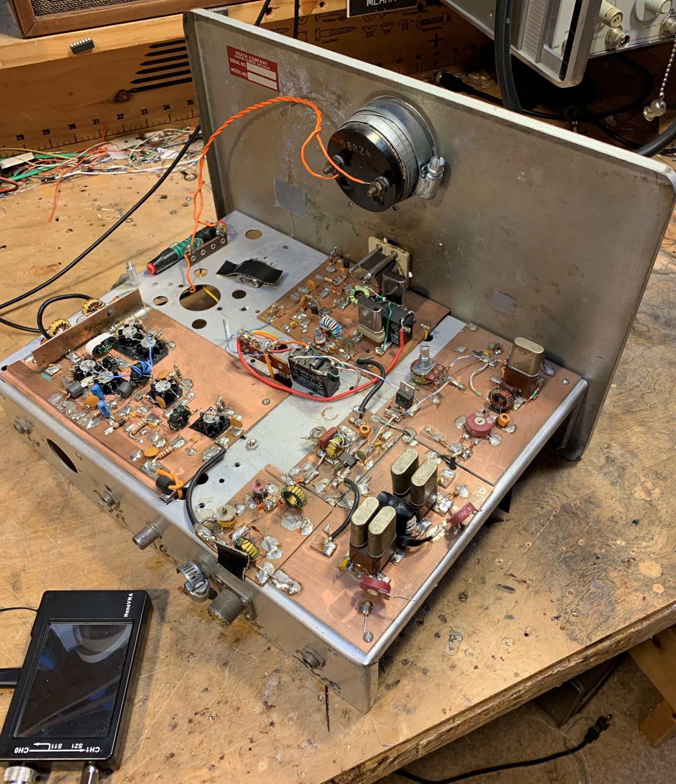
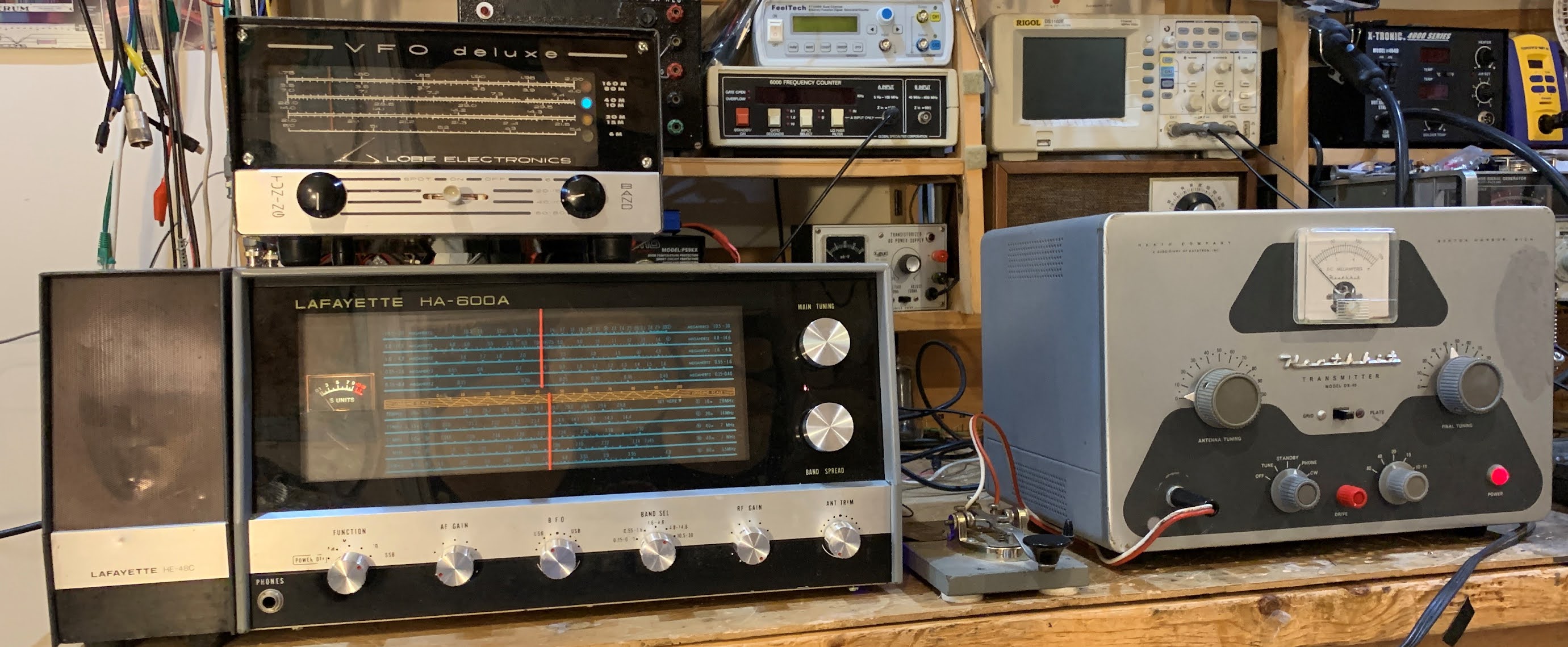
I built this receiver back in 1998, but I continue to have fun tinkering with it. I wrote an article about it for "Electric Radio" magazine (Number 115). One of the major shortcomings was the crystal filter that Lew McCoy prescribed. It was very difficult to get 455 kHz crystals to work well as filters. At various times I've had all kinds of replacements in there in place of Lew's filter: a 455 kHz IF can, a Toyo CM-5 hybrid ceramic filter, a fancy Millen high Q IF transformer. None of them really worked well.
Recently I put a little +/- 3 kHz ceramic filter in there. This is a 6 kHz wide filter at around 455 kHz. I think it works really well. Above you can see the receiver in action. I use it with a little powered computer AF amplified speaker -- I just don't like headphones.
The latest filter mod with the 6 kHz ceramic filter is shown above.
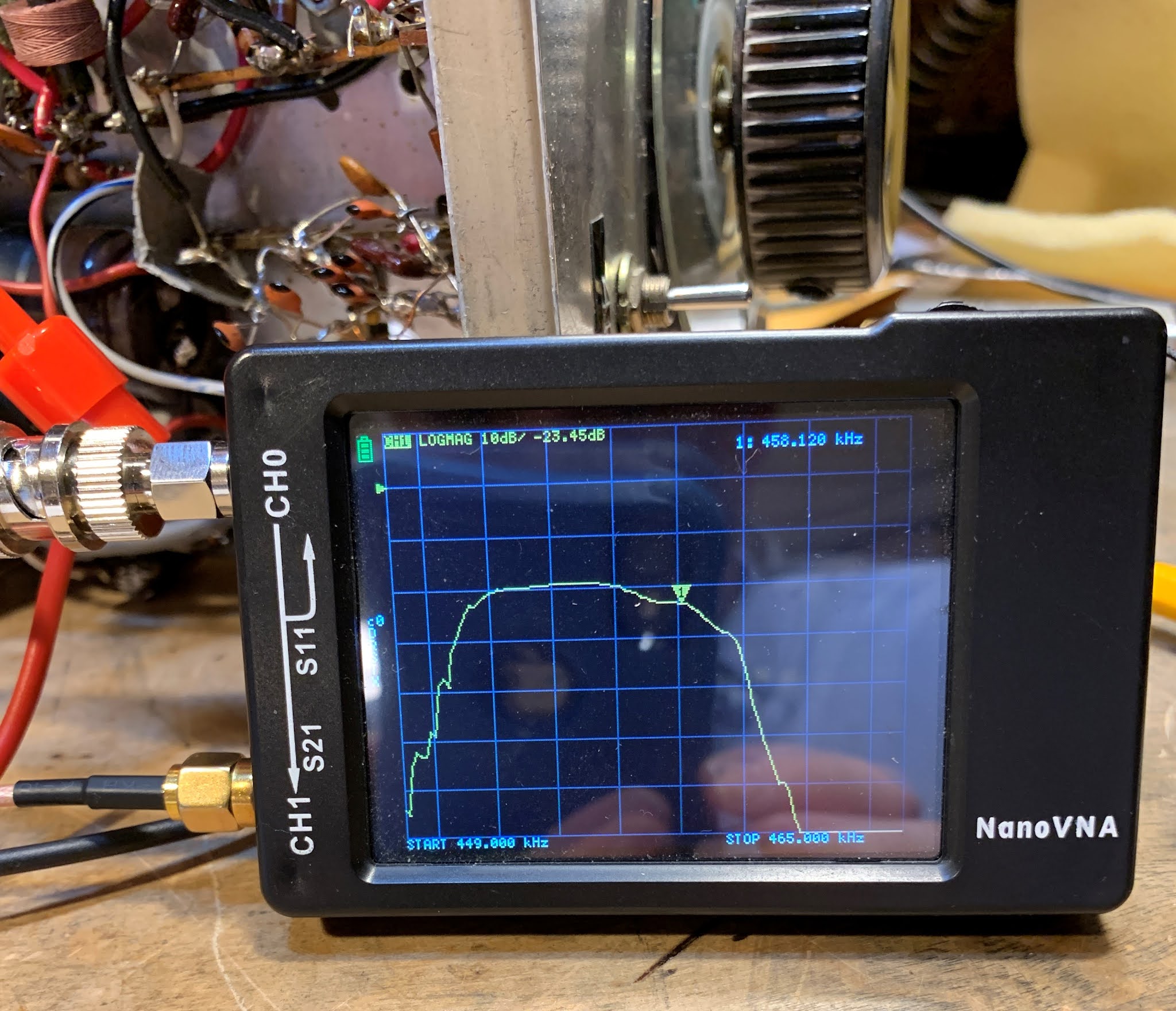
Above you can see what the whole 455 kHz filter and transformer passband looks like. The input was through a 2k resistor placed between the .001 uF cap and the filter. The output was also through a 2k resistor placed at the top of the secondary of T1. (So don't pay any attention to the insertion loss.)
The NanoVNA is displaying 2 kHz per division. I put the BFO at 451 kHz. This results is excellent opposite sideband rejection. The filter is really too wide for SSB, but it is about perfect for AM, which I listen to quite often on both 75 and 40. SSB and AM both sound quite good. Check out the video above.
It is kind of amazing what can be done with just three 6U8 tubes.
There are many previous SolderSmoke blog posts about the Mate for the Mighty Midget Receiver here:
This is Scott WA9WFA's first homebrew construction project. He did an amazing job on a very complex project: a 13 tube superhet receiver. It features plug-in coils for multi-band coverage, dual conversion with IFs at 1600 kHz and 100 kHz, and several regenerative stages. Scott's construction is top notch. He tells us that he had been working on this receiver for several years, so long in fact that some of his friends began to wonder if it really existed. Well wonder no more. Retirement has provided Scott with the time to finish this project.
I like the way Scott talks about the project in these videos. He puts it in the context of his long-standing goal of building his own high quality ham station. With the HBR-13 done, he is more than halfway there. We all know that the receiver is the hard part.
I agree with those who say that Scott should keep the plexiglass front panel. I think it looks very cool.
In the third video, Scott takes us on a cruise through the 40 meter band. The receiver sounds great. Lou EA3JE's booming voice came through quite nicely from far-off Barcelona.
Congratulations Scott on building a truly outstanding receiver. And on making some great videos.
There is some additional background info on the HBR-13 in this blog post from back in September:
The French "repairability index" is an interesting concept. I wonder how modern ham radio "radios" would score. I think our homebrew rigs would max out the index.
Pete has commented on manufacturing processes that do (or don't) factor in access for repair.
One of the recent horror stories we've heard is about a certain manufacturer of mobile phones. It seems that they have designed the phones so that if you dare to replace a broken screen, the new screen won't work unless you de-solder the associated chip, then re-solder in the SAME CHIP.
In his recent interview with Eric Guth, Courtney Duncan N5BF told us that the communication between the Ingenuity helicopter on Mars and the Perseverance rover is being handled by off-the-shelf Zigbee 900 MHz transceivers.
I did some Googling and found some more details on this:
----------------------------
"Once separated from the host spacecraft (lander or rover), the Mars Helicopter can only communicate to or becommanded from Earth via radio link. This link is implemented using a COTS 802:15:4 (Zig-Bee) standard 900 MHz chipset, SiFlex 02, originally manufactured by LS Research. Two identical SiFlex parts are used, one of which is an integral part of a base station mounted on the host spacecraft, the other being included in the helicopter electronics.
These radios are mounted on identical, custom PC boards which provide mechanical support, power, heat distribution,and other necessary infrastructure. The boards on each side of the link are connected to their respective custom antennas.
The helicopter antenna is a loaded quarter wave monopole positioned near the center of the solar panel (which also serves as ground plane) at the top of the entire helicopter assembly and is fed through a miniature coaxial cable routed through the mast to the electronics below. The radio is configured and exchanges data with the helicopter and base station system computers via UART.
One challenge in using off-the-shelf assemblies for electronics systems to be used on Mars is the low temperatures expected on the surface. At night, the antenna and cable assemblies will see temperatures as low as -140 C. Electronics assemblies on both base station and helicopter will be kept “warm” (not below -15 C) by heaters as required. Another challenge is antenna placement and accommodation on the larger host spacecraft. Each radio emits approximately 0.75 W power at 900 MHz with the board consuming up to 3 W supply power when transmitting and approximately 0.15 W while receiving. The link is designed to relay data at over-the-air rates of 20 kbps or 250 kbps over distances of up to 1000 m.
A one-way data transmission mode is used to recover data from the helicopter in real time during its brief sorties.When landed, a secure two-way mode is used. Due to protocol overhead and channel management, a maximum return throughput in flight of 200 kbps is expected while two-way throughputs as low as 10 kbps are supported if required by marginal, landed circumstances."
Yesterday I went through my novice logs from 1973-1974. I was in Congers, NY and my call was WN2QHL. Please take a look at the callsigns from my log and let me know if we had a contact. I will then let you have more details from my log.
There are a number of good ideas in this video. We've known for a long time that many expensive mics are really simple, cheap mic capsules in fancy packaging. This video takes a $12 mic capsule (which looks a bit like the ones we are using for the podcast), adds come amplification, a USB interface, and some really cool looking bronze packaging to come up with a very nice microphone.
I liked his use of solder wick as a shield for the DIY mic cable. Who knew the wick was hollow! I also like the cooking torch for use in soldering the brass. I need one of those. The little Murata DC voltage booster with positive and negative output seems useful.
It seems that anyone working on this kind of project quickly gets pulled into the use of "audio speak." Late in the video Matt says his mic has nice low-end "presence." A quick look at the comments section shows one person saying that one or the other of the mics sounds a bit "moist."
There are many other similarly interesting projects on Matt's YouTube channel:
This morning Eric Guth has a really interesting interview on his QSO Today podcast.
Courtney Duncan N5BF had a full career at JPL and is the current president of the San Bernardino Microwave Society. There is a lot of interesting stuff in this interview, much of it about space exploration. Courtney tells us about how experience with re-purposing radio gear came in handy at JPL. For example, the helicopter that they have been flying on Mars has a very cheap and light off-the-shelf Zigbee transceiver. He also talks about the origins of the Cube Sats.
Here is Eric's page on this interview, with useful show notes:
I really liked Nick M0NTV's approach to making a crystal filter (see video above). He really simplifies a process that desperately needs simplification. I remember when I was building my first superhet receiver, I came across Doug DeMaw's schematic for a crystal tester that would allow me to properly build the filter. But the piece of test gear was far more complicated than the receiver I was building. I never built Doug's device.
Nick's technique is simpler even than the G3UUR method that many of us have been using for years. Nick dispenses -- wisely I think -- with the need to calculate motional parameters, Q, and equivalent series resistance. This also eliminates the need to fidget around with the design software such as Dishal or AADE.
Nick uses the Cohn topology (good choice) and uses kind of an "informed cut-and-try" technique to come up with the capacitor values.
Filter impedance is determined with series trimmer resistors and the NanoVNA to watch the resulting passband. Nick says this is a Charlie Morris ZL2CTM suggestion. It obviously works very well -- the ripple that would result from impedance mismatch is eliminated.
Nick's determination of the best turns ratio for the impedance matching transformers is brilliant.
Nick apologizes for what he says is a long video. But it is only 30 minutes or so long, and if you are going to build your own superhet or SSB filter rig, it is well worth watching.
Three cheers for Nick and for Charlie! Thanks guys!
A few days ago I put up a blog post about using a noise generator (in my case my cheap FeelTech sig generator) and my TinySA spectrum analyzer to look at the passband of a crystal filter. I was using the 9 MHz filter used by Dean KK4DAS and the Vienna Wireless Makers Group. The idea is simple: insert broadband noise into the input. The filter should pass more of the noise that falls within its passband. The TinySA should let you see this. At first, I was pleased that I could clearly see the passband. I thought I had succeeded. See above.
But I was bothered by something. Look at that bump in the passband. It should be close to flat across the top.
I decided to take a look at the same filter with my NanoVNA. Here I was not using a noise generator. The NanoVNA sweeps the filter using and looks at output in the Log-Mag mode. Here is what it looked like (below):
That was much better. But why the difference? Tony Fishpool G4WIF suggested that my noise source might not be putting out noise at the same level on all frequencies. I took at look at the noise output of the FeelTech sig gen in the range of the filter passband (with some above and below frequencies for reference) and I found that the flatness of this noise depended a lot on what frequency I had the sig gen set to. I tuned it around a bit until I found a setting that produced a flat noise output in the desired frequency range. Then I went back and swept the filter with the noise and the TinySA again. Here is what it looked like with the "flat" noise:
Better, I think. Closer to the passband displayed by the NanoVNA.
Tony points out that these Chinese sig gens don't really put out random noise -- they give us predictable noise. Dean said "Predictable Noise" would be a good name for a rock group. I said they could open for my favorite: "The Ceramic Spurs."
The presentation starts at about the 4 minute point.
I think if I were only allowed to watch one YouTube video in the next year, I'd make it this one.
In this amazing RSGB video, Ashhar Farhan VU2ESE takes us back to his earliest days as a radio amateur. He tells us about his very early desire to build radios, his early projects, and his personal evolution as a designer and builder, from a simple DC receiver, to the BITX, the Minima, the uBITX and now the hybrid HDR/SDR sBITX.
There is a lot of homebrew wisdom and tribal knowledge in this video. And we learn so many hitherto unknown details about the rigs that have become so important to us:
-- Farhan had the EMRFD book with him on the famous flight from Sweden to India during which the BITX was designed.
-- We learn about the origins of the BITX oscillator circuits, and that the VFO and BFO are essentially the same.
-- I was really pleased that Farhan included a picture of my HB BITX17 rig in his presentation.
-- Farhan discusses the difficulties he faced in obtaining needed parts in India.
-- We actually see the nylon washers that Farhan used in the original BITX.
-- Farhan discusses his early system for measuring coil inductance.
-- In addition the huge contribution of EMRFD, Farhan talks about how he was helped by Pat Hawker G3VA's writing, and the ARRL's SSB Handbook.
-- Farhkan talks about his Tex 465 'scope and his building of a Spectrum Analyzer.
-- We see his evolution to dual conversion. We see the conceptual birth of the Minima and the birth (thanks Wes!) of the TIA amps. I didn't know about the HF-1. Then Farhan designed the uBITX and now the sBITX.
-- Farhan talks about his practice of taking the pictures of new rigs with the new rig sitting atop the book that was most important in its design and construction. FB.
-- I was really blown away by Farhan's presentation of how the uBITX advertisement was inspired by and in many ways based on the Heathkit ad for an HW-101. Amazing.
-- I learned a lot from Farhan's discussion of SDR theory. I pledge to spend more time with this. I really like Farhan's hybrid HDR/SDR approach.
-- But I have a question: Farhan seems to say that we'd need a big expensive GOOGL computer to do the direct sampling HF SDR. But doesn't the little RTL-SDR do just that? Without a GOOGL?
-- Great to see Wes's AFTIA being used in the sBITX.
-- Really cool that Farhan has his mind on VHF transverters when designing the sBITX. I liked use of the TCXO module to free up one of the Si5351 clock outputs. FB. And great to include an idea from Hans in this rig.
Thanks very much to Farhan (who stayed up until 3 am to do this!) and to the RSGB for hosting.
Only 85,000 Euros (that's the opening bid). But hey, it comes with the receiver pictured on the right. I guess that's so you can listen to the beeps.
Here's the description:
---------------
Laboratory Test Model of "Sputnik 1 EMC/EMI", 1957 1:1 scale test model of the satellite "Sputnik-1", serial no. "0K6-1/004/1957", with built-in transmitter (including modern 12-volt power supply), polished stainless-steel sphere, consisting of two threaded hemispheres of approx. 23 in. diameter with two pairs of antennae of 95 in. and 105 in. at an angle of 35 degrees to the axis, on stand with O-ring, stand approx. 59 in. high, stand and model together approx. 79 in. high, accompanied by a Tesla Maj 620A radio receiver, manufactured in Prague c. 1956, restored working condition, including replacement of the silver-zinc battery with a modern alternative and a new metal casing for the electronic transmitter. Note: Built at the Experimental Design Bureau-1 (OK?-1/OKB-1) factory, also known as S.P. Korolev Rocket and Space Corporation Energia, Koroljow, Soviet Union, in 1957, shortly before the launch of Sputnik-1. - An impressive artefact from the dawn of the space age, of which few models are known. - Provenance: From the collection of Dr. Frank Malina, USA/CSSR.
Start Price: EUR 85.000
---------------------------
I'm a bit suspicious of the "modern 12-volt power supply," the "modern alternative" battery and the "new metal casing for the electronic transmitter."
Here's my suggestion: Musk or Bezos or Branson should buy this thing, fix it up a bit, and put it back in orbit. So we can listen to it again. I know a version of this was done back in 1997. But I think we should do it again, this time with the actual test model.
Here are the earlier SolderSmoke blog posts about Sputnik and Sputnik-related projects:
Steve Silverman sent the auction posting to me. Thanks Steve.
It just so happens that earlier in the week I was out at the Air and Space Museum facility near Dulles Airport, where I saw this flight backup of the Vanguard satellite:
I've been meaning to try this for a long time. Years ago Tony Fishpool and Graham Firth wrote about using a noise generator and a spectrum analyzer to sweep the bandpass of a filter. The idea here is to send very broadband noise into a filter, and then use a spectrum analyzer to see which frequencies make it through.
I thought about building a noise generator like the one in Tony and Graham's book, but then it occurred to me that probably had one sitting on my bench. Sure enough, a look at the manual for my cheap FeelTech function generator revealed that PRESETS 3 and 8 are noise generators. I quickly pulled out a 9 MHz filter that Dean KK4DAS had given me, put the noise into one end and the TinySA on the other end. Bob was quickly my uncle. See above.
More recently Tony G4WIF built a comb generator as a noise source:
Because our podcast and blog is called SolderSmoke, I felt compelled to post about this video in which a fellow does some pretty interesting research into how solder smoke actually moves. We don't often see this much concern about the behavior of our beloved smoke.
"SolderSmoke -- Global Adventures in Wireless Electronics" is now available as an e-book for Amazon's Kindle.
Here's the site:
http://www.amazon.com/dp/B004V9FIVW
Re: 20 meter AM in 2024
-
The AM designated 20 meter "calling frequency" for years has been 14.286
MHz. Because of lots of activity and nets around that frequency, many
AM'ers moved...
May 18, 2024. Any one have one of these?
-
With a price point of about $250 you would think this is like hitting the
lottery. Any blog readers have one of these?
This is the Xiegu G106C currently ...
Velocity factor measurement
-
A frequently asked question is how to measure transmission line velocity
factor. The wide adoption of the NanoVNA has spurred these questions. So,
it is go...
ICOM hint at new 60th anniversary X60 product
-
At the Dayton Hamvention this weekend, ICOM put on display are number of
printed circuit boards from what is supposed to be the 60th Anniversary
Concept ...
Moorabbin Radiofest
-
The Moorabbin RadioFest was a terrific show this year. The turnout looked
good to me although I'm told it was down on past years.It was great to see
a vend...
Broadcast Band AM Radio
-
See the YouTube series for more information:
http://www.youtube.com/c/CharlieMorrisZL2CTM
Buffer Amplifier
Low Pass Filter
IF Ampli...
An Inline RF Step Attenuator for QRPp Work
-
I don’t need to explain the attraction of low power operation; if you’re
reading this, the chances are that you are already a convert. I’ve been
operating ...
A 51S-1 Restoration Story
-
I came across my Collins 51S-1 in a big junkyard in Ankara, Turkey around
2012. It was in a pile with a lot of other electronic scrap, probably from
one o...
New QRP Cluster Online From OM0ET and OM6APN
-
By DX EXPLORER
DX EXPLORER
Paul OM0ET and Peter OM6APN recently launched a new cluster dedicated to
QRP operations. Have a look and I hope you will enjoy...
3D Printing The Hadley 114mm Newtonian Telescope
-
Yes, we’re building a 3D Printed Newtonian Telescope called Hadley. It’s
being printed in PETG and in the video below, I give a quick tour. My build
isn’...
3D printed project boxes
-
I have been busy with some other things that have kept me away from
electronics projects for quite a while. Now I can get back to them, but
realize I n...
Daylight Again – An all Analog Radio
-
What’s all this? In 10 seconds, A high performance, 7MHz, 5 watt SSB rig
Draws just 24 mA of current 90 dB dynamic range, 80 dB close-in dynamic
range 3D ...
Adding Enclosure to your sBitx Boards Order
-
The early buyers of the sBitx board set who bought it for $270 USD might
want to also add the enclosure (box) for in the kit. What you will now get
is a f...
Digi-chirp! Digital synthesis of ‘nostalgic’ CW
-
The bottom ends of 80, 40 and 20m are not what they used to be. For
starters, the busiest part is the digital segment where computers talk to
computers – l...
-
A Simple Speech Processor
(For QRP/SSB Homebrew Transceivers )
Over the last few weeks I had been thinking to build a small AF speech
processor to add to...
A New Look for your uBitx!
-
Adding a "Cool Blue" Display to your uBitx!
The standard "green background" with black lettering frequently reminds me
that I suffer from Chronic seasickn...