Podcasting since 2005! Listen to Latest SolderSmoke

Tuesday, February 7, 2017

ZL1UEM'S Tiny OLED Si5351 Arduino VFO


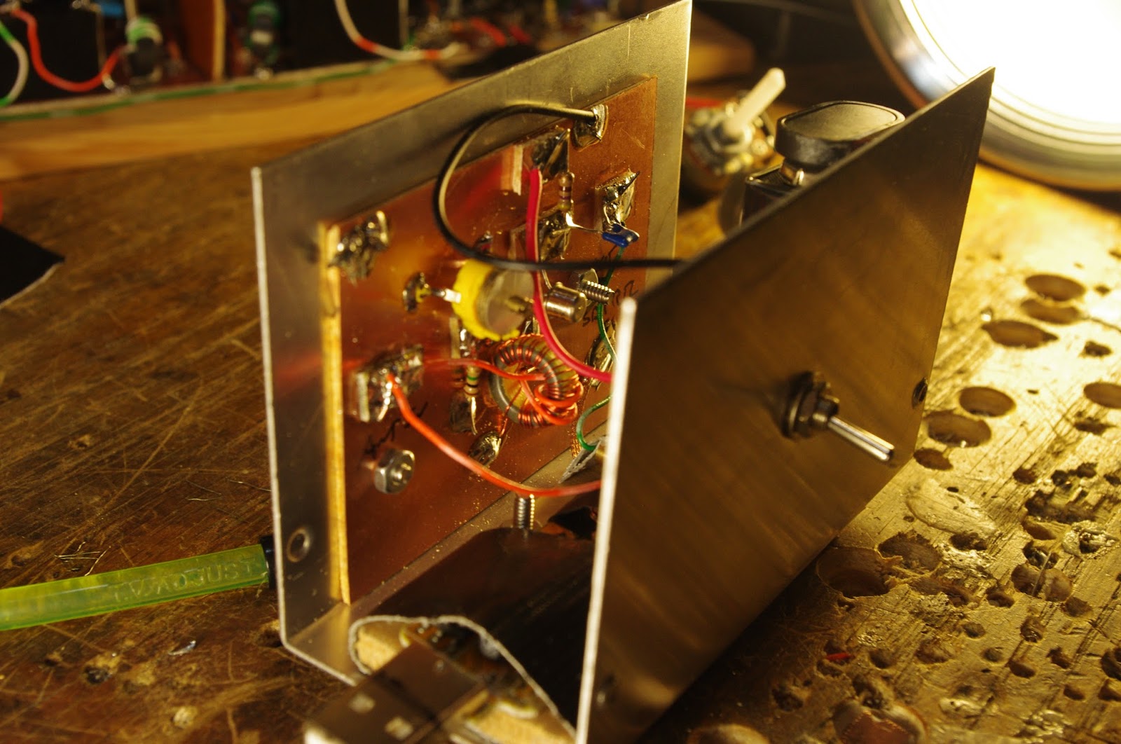
Hugh ZL1UEM has come up with a very creative way to take maximum advantage of the small size of the Si5351 board, the Arduino, and the OLED display.  He even has the rotary encoder in there.  Look carefully -- he uses both sides of the board.  Very nice. Thanks Hugh!

Hi Bill,

First let me say that I have been an avid follower of the SS blog and podcasts since the days of your podcasts involving Mike KL7R.

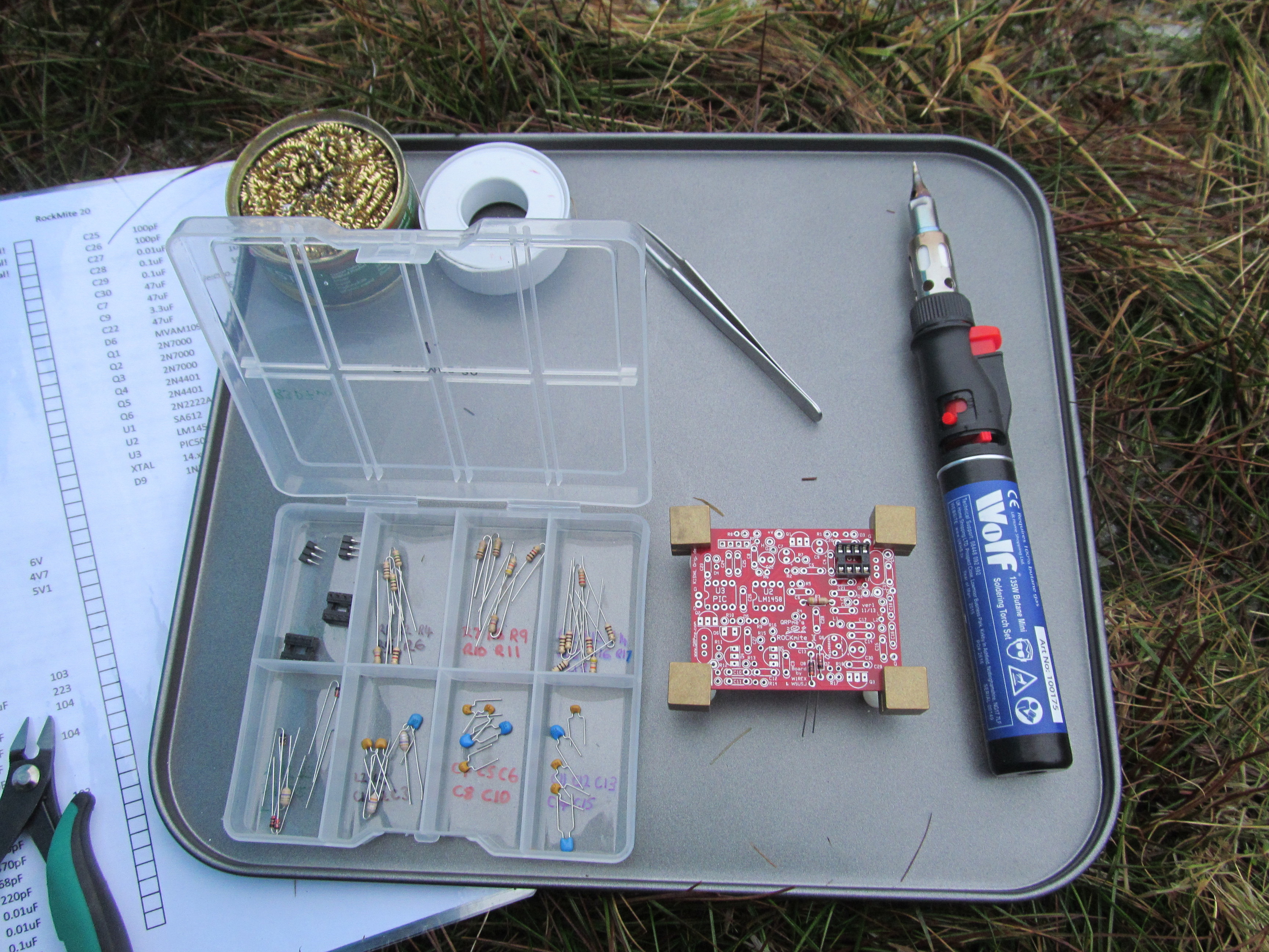
Like many others I was tempted to purchase the $49 surface mount module from HF Signals.  As a keen home brewer I felt guilty about employing a prebuilt board but excused my decision on the grounds that I would build a DDS and other accessories myself.

In addition to follow the SS blog I also check Pete's blog regularly and was excited by his OLED VFO for the Bitx40.

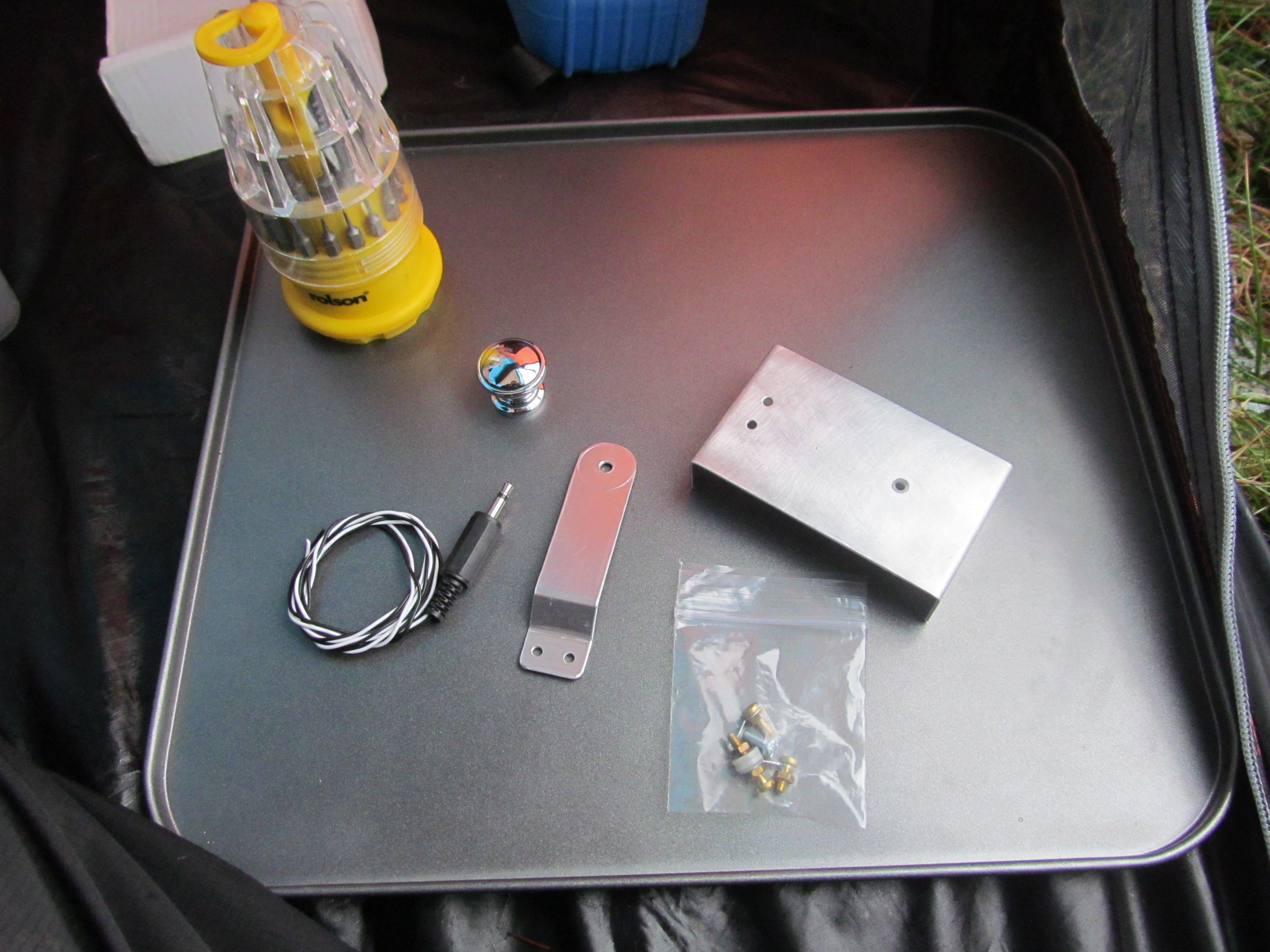
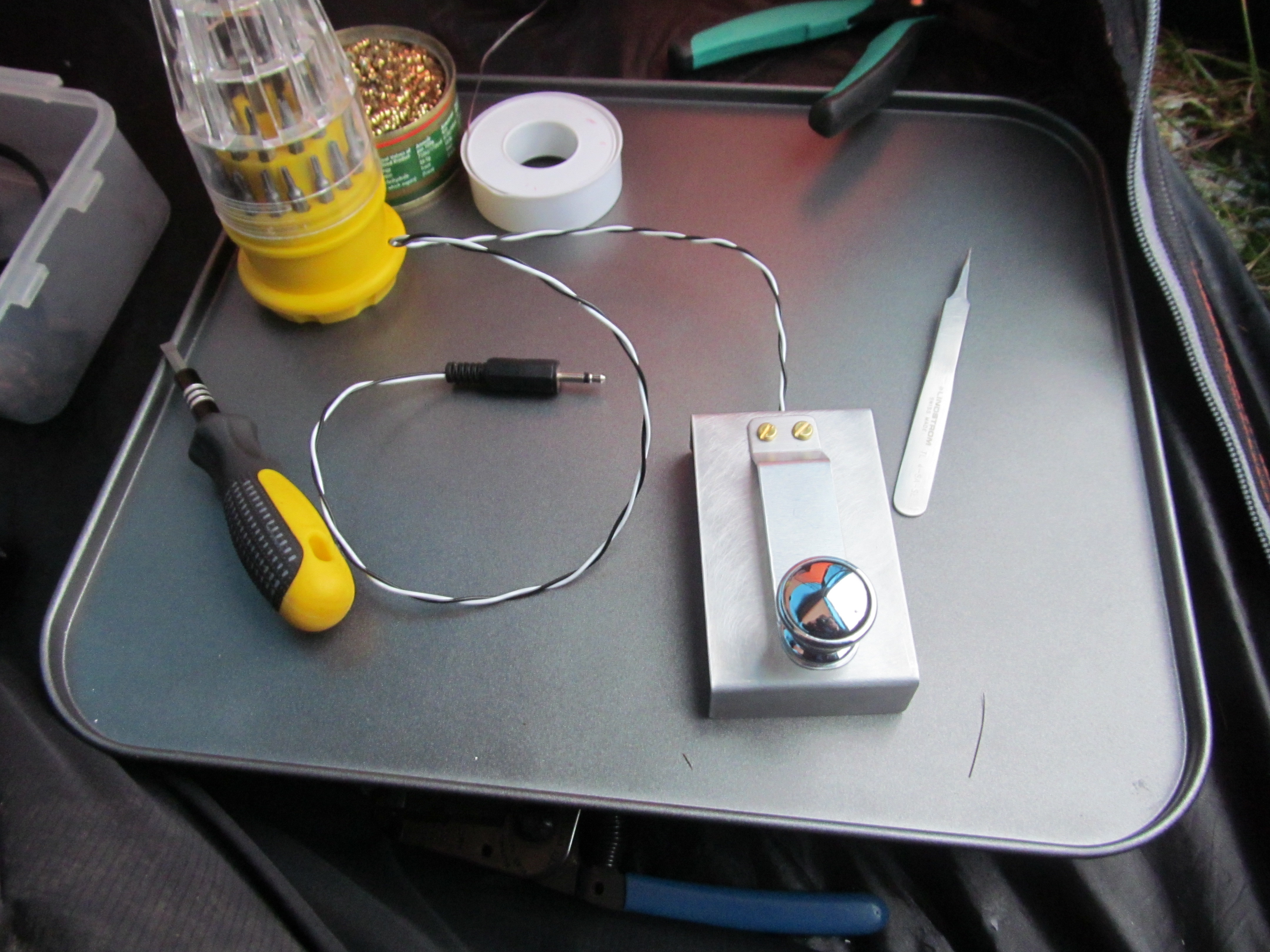
I constructed it on a small double sided matrix board with plated through holes.  A bit of noodling led to the layout shown in the photos.  There is only one board with components mounted on both sides.  The board came to life on the first power up but the text spilled off the bottom of the display.

I assumed that the sketch that I had downloaded from Pete's blog was for a different OLED module.  I knew that he had also used a yellow/blue OLED, the same as mine, previously so emailed him requesting a sketch for this OLED.

I was taken aback when he informed me that the sketch I had was the same for both the dual colour OLED and the black and white one too.  Pete suggested that I swot up on the use of OLEDs generally and that perhaps I should first experiment with the text size to begin with.  He also offered some advice about the mapping of the screen.

I soon discovered that the text size was not the cause of my grief and that I needed to look elsewhere.

I first tried running the ssd1306_128x64_I2c sketch from the sample sketch folder and was rewarded with the message "Height incorrect, please fix Adafruit _SSD1306.h".  A search of the Internet revealed that I needed to edit the .h file and find "#define SSD1306_128_64" which was commented out and uncomment it and make sure that the other two options, _32 and _16, were commented out.

My next problem was how to edit the specified .h file.  I tried notepad but the text all ran together.  Another internet search revealed that Notepad++ was a suitable choice and it did indeed cut the mustard.

A reload of the sketch completely restored the display to full functionality.

All this may be obvious to many but it was all new to me and if I had not been prompted by Pete l would not have had learnt so much and would not have had the same sense of achievement when it all came together.

Many thanks to you and Pete for providing a focus for my hobby.

73's
Hugh ZL1UEM

Schematic for the RTL SDR Dongle Front End

Here it is.  Very simple.   I used an obsolete 40673 dual gate MOSFET.  I didn't need both gates so I just soldered them together. You could probably substitute an easily obtained MPF-102  JFET.  The capacitors and the coil in in the gate circuit form a parallel LC filter circuit that resonates in the 40 meter ham band.   The 1 Megohm resistor maintains a very high impedance for the LC circuit, helping to maintain circuit Q (sharp response).  It also drains off any charge that builds up on the gates.  For the antenna input I just put 2 turns on the 4.5uH coil -- this too helps maintain LC filter response.  The 470 ohm resistor serves as the load and limits quiescent current through the MOSFET.  It should pull about 19 milliamps -- with a 9V battery that should give you around 26 hours of listening time between battery changes.  That's fine with me -- I don't use this thing that much. 

Realize that I'm using this with an RTL-SDR dongle that has been given the familiar modification that allows it to use direct sampling in the HF bands.   Some ideas here:
and here
and here


Monday, February 6, 2017

Adding a Homebrew Front End to an RTL-SDR HDSDR Receiver

I started playing with the RTL SDR dongles again.  I wanted to use them to confirm that my BITX signal is NOT 9 kc wide (it is not).  I also wanted to try to confirm the aircraft band frequencies in use in this area.

So I got the HDSDR software running and plugged in the dongle that I had modified for HF use.  It worked great, but I could see (literally SEE) that it needed some bandpass filtering and perhaps a bit of RF gain.  So today I threw together this device.  Dual gate MOSFET (gates tied together) with an LC filter on the gate.  Power from Malaysia via the 9V battery.

It works great. It was fun to add a bit of homebrew to an otherwise soul-less commercial receiver.   But beware: that waterfall is addictive, even for a hardcore Hardware Defined Radio guy like me.

Sunday, February 5, 2017

"First Light" on Brad's Direct Conversion Receiver

So cool.    You can just feel the enthusiasm.  Congratulations Brad!

Bill and Pete:

After 63 years, I was finally able to build a DC receiver of my own design.  We achieved "first light" at 7:20P last night.  I attached the antenna, speaker, then applied power - and a all of a sudden "Bob's your uncle!!"  There are some things I still don't quite understand but right now none of that matters as I listen to the sound of clean, crisp CW pouring out of the speaker and filling the room!!  Major components - SI5351, SBL-1, TL072 op amp bandwidth filter, LM386 audio amp.  I plan to use clk2 of the SI5351 with some Arduino code to create the companion transmitter and CW keyer.  Life is good!!!

Brad WA8WDQ

Saturday, February 4, 2017

W8LM's BITX on a Board


The purpose of the BITX40 project was to encourage modification, experimentation, and more frequent melting of solder.  I think these pictures from W8LM serve as yet another reminder that this goal is being achieved.  The contrast with the big appliance rig in the background is, in so many ways, striking. You'd be understandably reluctant to take a soldering iron to the commercial rig, but the BITX seems to be crying out for hot iron and solder smoke. 

W8LM wrote (on the BITX20 group):

Guys- Here are pix's of my BITX40 fired up today in Receive for testing. #1 I have the tuning clicks- so I will be debugging that. #2 shown in the pictures is my test of calibration which was not necessary. I used a T and put my ICOM 756proII  and the BITX40 on the same antenna (a Windom flat top at 33Ft)  The display of both read 7.1700 pretty much the center of the band and I was copying 4's,8's and 2's at 23:30zulu) By moving volume controls up and down I could listen to both rigs same frequency, audio comparison acceptable. An AGC circuit is in order.  The mylar-plastic cone of the surplus speaker lacks fidelity. Unfortunately the 16x2 display did photograph well. It's a start-- de W8LM

Friday, February 3, 2017

A Mighty Mite, a BITX40, an ILER, some Arduinos, and the Joy of Oscillation in the United Arab Emirates


Martin A65DC sent us this wonderful report on his efforts in the UAE.  His e-mail nicely conveys his enthusiasm.  I was especially pleased to see that wooden enclosures are catching on (another fellow on the BITX20 group is using a cigar humidor).  Thanks Martin!  Please keep us posted on your UAE homebrew adventures.

Hi Bill and Pete,

My name is Martin, and I am listening to every episode, sometimes more than once, thank you for an excellent show boys. I am a ham in the United Arab Emirates and operate radio as A65DC.

I just wanted to share my "JOY OF OSCILLATION” moment with you, I had the moment two days or so ago.. fantastic!

Well it is not super tidy, but as a proof of concept is totally acceptable. red and green goes to the variable cap (above).

Next to the Mighty Mite (above) is my bitX40, what a fantastic board!! I have big plans for this radio. But for now it will stay in its wooden box and keeps me company.


This (above) is another kit build, 20m SSB kit from EA3GCY Javier. ILER20, please have a look, this is where you should start if you are into kit building!! the instructions are fantastic.
I added some Arduino magic to it with a SI5351, and then I was sitting and looking at my big UNO board, hmmm USB port, why not further develop the code and use the port as CAT control.
I can now connect this rig to e.g. N1MM and control it, read and write frequency (in current version) I am simulating the protocol of a TS590, but that turned out to be a bad choice, I should have gone for a simpler radio, like a 140 or something, the 590 has loads of CAT commands that my code needs to answer… this radio is my QRO 20m as rig it sports the 20w amplifier kit from K5BCQ and will put out a whooping 22w!  Several contacts from A6 into Europe and some over to Indonesia.. fun stuff, two kits from different vendors together with some own building and coding.. I love it.


On the workbench now is an Arduino CW keyed based on K3NG, the Arduino code is very well written and it has loads of functionality, most of what I will never use.. but as a keyer it is superb.
This is my keyed circuit, super simple stuff, it is here connected to the Mighty Mite as a test, works 100%  I am now researching a good circuit for a CW transmitter/transceiver for 40m that will be in the 5 to 10w range to use my new keyer with.

Again, thanks for a fantastic show guys,

73
A65DC, Martin

Wednesday, February 1, 2017

Colin M1BUU Achieves SOTA "Mountain Goat" Status -- With Rig Built ON THE MOUNTAIN TOP

Stiff upper lip OM!  MUSN'T GRUMBLE and all that...

Our friend and BITX builder Colin M1BUU has opened up a new area for ham radio masochism:  EXTREME MOUNTAIN-TOP RIG BUILDING.  That's right my friends.  You read that right. Colin has taken the solder smoke to new heights.   Soon,  these guys will be pouring scorn on those of us using "shack built" rigs.  Congratulations Colin!   Well done! 

Colin's write up from http://reflector.sota.org.uk/t/colin-m1buu-mountain-goat/14559  :

The general story goes something like this -
I started with SOTA way back in 2004, aged 24. Just after I found SOTA, I also found love - Fiona and I will celebrate our 10th wedding anniversary in April. You know how the story goes..........
Winter time has generally been quiet in terms of family stuff, so it's generally this time of year when I activate, usually January to March.
You've heard of extreme ironing, right?


Being a prolific builder of radio kits, I thought I would do my own twist on Extreme Ironing - Extreme Solder Ironing!
Today was the day. I took a RockMite kit, a home made key kit and a home made vertical antenna kit up to the summit of Whernside G/NP-004. I assembled the kits using a gas powered soldering iron. Thankfully I took my little tent with me, the weather wasn't exactly tropical.
The kits went together well and the RockMite fired up first time without any debugging, although the building took much longer than I had reckoned.
I was late on air, but eventually Barry N1EU found me for my first contact. Shortly after followed SP9AMH, OH9XX and finally EU2MM to earn me my needed points. Mountain Goat was in the bag! The QSB was very evident today, QSO's were tough, except with OH9XX, who was ear blasting. :smile:
Firing up the FT817 (I intended to share my success with as many as possible!), I worked a handful more stations on CW and SSB, but my time was rapidly dwindling.


Finally, I'd like to say thanks for all the support given by numerous SOTA participants over the years, There's a number of great, inspirational people we've lost in that time and I think about lots of them all the time. Roger G4OWG was particularly on my mind today as I learned of the route I took today from one of his posts. I never met Roger in person, but he was a keen chaser and fairly local to me.
73, Colin
Edit - I forgot to put forward my thanks -
Thanks to Dennis G6YBC (Kanga Products) for sponsoring a RockMite ][ ver. 1 PCB
Also thanks to Pete G4ISJ for supplying the solder!
Designer: Douglas Bowman | Dimodifikasi oleh Abdul Munir Original Posting Rounders 3 Column