Podcasting since 2005! Listen to Latest SolderSmoke

Showing posts with label Australia. Show all posts

Monday, August 30, 2021

Adding Automatic Gain Control to the Termination Insensitive Amplifier

 
Earlier this month Paul VK3HN had a very interesting blog post about adding Automatic Gain Control to Termination Insensitive Amplifiers (TIAs).  

Termination Insensitivity is especially important in bidirectional rigs.  The shape of the crystal filter bandpass response is very dependent on the impedances presented at both ends of the filter.  In bidirectional rigs you are changing the signal path direction through the filter when you go from transmit to receive.  If the amplifiers at either end of the filter have impedances that vary depending on what is on the input or output of either stage, you will have great difficulty keeping the bandpass identical as you move from transmit to receive.  Termination Insensitive Amplifiers let you do just that -- they stay at one fixed input or output impedance (usually 50 ohms) independent of what is attached to the other end of the amplifier circuit.  This greatly simplifies impedance matching at the ends of the crystal filter. 

When I started building BITX rigs, I asked Farhan about the impedance matching problem.  He advised me to use TIAs on both ends of the filter and pointed me to a great 2009 article by Wes Hayward and Bob Kopski.  Using the information from that article, I built my DIGI-TIA transceiver, and I have used TIAs in almost all of the rigs I have built since that project.   

In his August 2021 blog post, Paul wanted to add Automatic Gain Control to the TIAs. He came up with a way to do this, but we worried that his circuit would have an impact on the impedance of the amplifiers. 

Yesterday, Wes Hayward W7ZOI posted on his web site a TIA circuit that lets us do it all:  Termination Insensitivity with Automatic Gain Control: 


I now find myself tempted to rebuild one of the TIA stages in my Mythbuster transceiver, adding the AGC circuitry from Wes's design. 

Thanks to Paul VK3HN for the blog post on this subject. And thanks to Wes Hayward for the TIA AGC design.  It is a real privilege to have direct input from Wes on questions like this. 

Sunday, June 6, 2021

VK3HN on Scratch Building (Video)


Lots of wisdom and good info in Paul Taylor's presentation.

Paul's comment on the impact of abundant LiPo power in the field -- we no longer have to scrimp and optimize power consumption -- was very interesting.   

And thanks for the nice mentions of the SolderSmoke podcast. 

Thanks Paul!

https://vimeo.com/showcase/8253187?page=5

Saturday, May 22, 2021

Tuesday, May 18, 2021

HRDX Interviews Paul Taylor VK3HN


Wow, Paul Taylor, VK3HN is working on homebrew rig #11.  FB.  

This interview was quite thought-provoking. 

-- I agree with Paul about the importance of not being dogmatic about 
always staying under 5 watts.  It sounds like Paul is having fun with his 
100 watt SOTA project. 

-- It was great  to hear that Leon VK2DOB is still active in ham radio and running a QRP company in VK.  FB.  An article by Leon on CMOS mixers in the summer 1999 issue of SPRAT played a key role in my understanding how switching mixers really work.  I put Leon's diagram in my book SolderSmoke -- Global Adventures in Wireless Electronics. 

-- On blowing up the finals in simple HB gear.  The first real transmitter that I built was the VXO-controlled 6 watter from QRP Classics by the ARRL.  It had a 36 volt Zener diode across the collectors of the final.  This was to prevent the kind of final destruction Paul suffered up on that summit:  "D2 is used to clamp the collector voltage waveform to protect the output transistors if the transmitter is operated into an open circuit or high SWR antenna system."  Maybe we should revive the use of that simple SWR protection circuit, especially for SOTA rigs. 

Wednesday, March 31, 2021

Mending vs. Ending -- The Fight Against Planned Obsolescence


We don't get a lot of mail from Darwin, Australia, so the message coming in from Phil VK8MC immediately got our attention.  When I looked into the details I realized that it was very SolderSmoke-relevant.  The Guardian article that Phil cited even mentions hobbyists tinkering with electronic devices in their sheds (that would be us!).    Phil points to the connection between our repair efforts and the struggle to save the planet: "It's not just a hobby, it's an ethical position which contributes to the well being of the planet. A higher calling indeed!" 

Here is the article Phil pointed us to:

https://www.theguardian.com/commentisfree/2021/mar/17/ending-over-mending-planned-obsolescence-is-killing-the-planet?CMP=Share_AndroidApp_ProtonMail

The poster above (which hangs above my workbench) is from https://www.ifixit.com/Manifesto


Monday, March 15, 2021

Aladdin's Lamp == The Vacuum Tube (aka The Thermatron) (Video)


After our posting of the video about 1957 transistor production, our friend Peter O'Connell VK2EMU asked for some equal time for vacuum tubes.  He sent me this 1940 Western Electric video.  It is quite interesting. 

-- I like the Aladdin's lamp metaphor.  When I was out in the Azores I thought of my homebrew 17 meter DSB rig as my "magic carpet." 

-- Lowell Thomas was brought in to narrate.  His voice sounds a lot more natural than that used to narrate the transistor film. 

-- To explain the effectiveness of transcontinental telephony with vacuum tube repeaters, they compared the system that of a relay of "hog callers" claiming that it would take 100,000 hog callers to carry a signal from New York to San Francisco.  So perhaps this could be a rival to db?   100,000 hc? 

-- Arlington to Paris 1915 caught my eye -- Arlington Va. is right down the road. 

-- The film of Edison in his lab was good to see.  And note the importance of his lab notebooks. 

-- The explanation of thermionic emission was quite good.  But of course too much credit was given to Lee DeForest. 

-- The breathless description of the amazing uses of tube technology was for me a reminder of how recent this technology is.  My father started as New York City cop in the 1950s.  He always referred to his police car as a "radio car." 

Hey, are any radio amateurs out there using one of those big water-cooled tubes?  If not, why not? 

Thursday, November 26, 2020

VK3YE's Super Simple Phasing Receiver


Really simple, really nice.  I like the innovative way they achieved the RF quadrature: they did it by splitting and phase-shifting the RF signal, not the VFO signal.  I also like Peter's use of the AM broadcast signal to demonstrate the sideband suppression. Then, SSTV for icing on the cake. 

Sunday, November 22, 2020

The Wizard of Horseshoe Bend: VK2FC's Wonderful Projects

 
Google led me to VK2FC's amazing site.  I was digging up info on product detectors and I landed on Glen's description of his version of the W7ZOI Progressive Receiver.  Glen's website provides a very detailed, board-by-board description of how to build this great receiver.  I now want to build one. 

http://www.vk2fc.com/progressive_receiver.php

Glen's site has many other projects.  Check them out: 

http://www.vk2fc.com/index.php

And here he is, the Wizard of Horseshoe Bend: 


Thanks Glen. 

Saturday, November 14, 2020

The Dish -- Virtual Tour -- New Indigenous Name


Thanks to Peter VK2EMU for this update on the Parkes radio telescope.  Parkes is the subject of our favorite movie about an antenna:  'The Dish."   If you haven't seen it, well, you are just wrong. 

The video update is very nice, with an interesting juxtaposition of old and new test gear.  

But the coolest thing that Peter sent us is the story of the Parkes Radio Telescope's new indigenous name: Murriyang in the Wiradjuri language: 


Thanks Peter. 

Friday, November 13, 2020

How Does My Singly Balanced, Two-Diode, Single Transformer Product Detector Really Work?


As young James Clerk Maxwell used to say, "What's the go of it?"  and "What's the particular go of it?"

I studied this circuit carefully when I was using it as a balanced modulator in my DSB rigs.  I wrote up my conclusions in my book "SolderSmoke -- Global Adventures in Wireless Electronics." 

BALANCED MODULATOR CONFIGURATION: 

When I was using it as a balanced modulator, I had the RF "carrier" signal going into L1. This RF signal was 7 dbm, enough to switch the diodes on at voltage peaks.  With the "center tap" of L2/L3 grounded for RF, this meant that when the "top" of L2 is negative, the "bottom"  of L3 is positive.  In this situation BOTH D1 and D2 will turn on and conduct. 

When the top of L2 is positive, the bottom of L3 is negative and neither of the diodes is on.  Neither conducts. 

So we have the RF signal turning the diodes on and off at the frequency of the RF signal.  

Audio from the microphone and mic amplifier is sent into the center tap connecting L2 and L3.  The level of this audio is kept low, below the point where is could turn on the diodes.  The center tap IS grounded for RF by the .1uF capacitor, but it is NOT grounded for AF.  That is key to understanding this circuit. 

In essence by turning the two diodes on and off at the rate of the RF signal, the audio signal is facing severe non-linearity through the diodes.  We could say it is alternately being multiplied by 1 and 0.  This non-linearity is what is required for mixing.  We therefor get sum and difference products:  Sidebands.  At this point, Double Sideband.  

The way the transformer is set up means the RF carrier signal is balanced out:  Even when the two diodes conduct, the top of R1 and the bottom of R2 are of equal and opposite polarity, so there is no carrier signal at the junction of R1 and R2 (they are actually a 100 ohm variable resistor that can be adjusted to make SURE they balance out).  So the carrier is suppressed and all that remains are the sidebands:  Suppressed Carrier Double Sideband. 

PRODUCT DETECTOR CONFIGURATION:

What happens when we use this circuit as a product detector in a receiver? Let's assume we are working with a 455 kc IF.   If you run a 454 kc 7 dbm BFO signal into L1, it will turn the diodes on and off as described above.  But you will NOT be able to put the 455 kc IF signal into the center tap of L2/L3 -- that center tap is GROUNDED for 455 kc.   So you will have to run your IF signal into the resistors, and take the audio output from the center tap of L2/L3.   This works.   I tried it in my HA-600A.  But there is a problem: Envelope detection.  

In this arrangement, we are balancing out NOT the 455 kc IF signal, but instead we are balancing out the BFO.  We don't really NEED to balance out the BFO -- it can easily be knocked down in the audio amplifiers, and IT is not responsible for the problematic envelope detection.  We DO need to balance out the IF signal, because if that gets through we can get simultaneous "envelope detection" and product detection.   And believe me,  that does not sound good.

So I tried putting the IF signal into L1, and the BFO signal into the resistors (as shown above).  I took the audio  from the junction of L2/L3.  This seemed work better, with envelope detection greatly reduced. 

BUT WHAT'S THE GO OF IT? 

But how is this circuit mixing in this configuration?   The strong BFO signal is still controlling the diodes, BUT, with the BFO signal coming in through the resistors,  when the top of R1 is positive the bottom of R2 is ALSO positive.  In this situation D1 will conduct but D2 will not.  The IF signal is facing a big non-linearity. This will result in sum and difference frequencies.  The difference frequency will be audio.  But with D1 and D2 turning on and off in a very different way than we saw in the balanced modulator, how does the mixing happen?  

I think the answer comes from the summer 1999 issue of SPRAT, the amazing journal of the G-QRP club.  Leon Williams, VK2DOB wrote an article entitled "CMOS Mixer Experiments."  

Here is Leon's 74HC4066 circuit: 


I think those two gates (3,4,5 and 1,2, 13) are the functional equivalent equivalent of the two diodes in our product detector. In Leon's scheme the VFO is supplying signals of opposite polarity.  Ours is providing only one signal, but the fact that the diodes are reversed means that they act just like the gates in Leon's circuit.  The transformer is almost identical to the one we use in the product detector. 

Let's look at the output from Leon's circuit: 


"VFO A" going high is the equivalent of the BFO going to its positive peak and D1 conducting. 
"VFO B" going high is the equivalent of the BFO signal to its negative peak and D2 conducting. 

Take a ruler, place it vertically across the waveforms and follow the progress at the output as the two signals (RF A and RF B) are alternately let through the gates (or the diodes).  You can see the complex wave form that results.  The dashed line marked Audio Output shows the difference frequency -- the audio.  That is what we sent to to the AF amplifiers. 

One concern remains:   

What happens when the 455 kc IF signal getting to L1 get so strong that IT also starts to turn the diodes on and off?   I think this will result in distortion, and we can see this in LT Spice.  

Here is the output waveform when the If signal at L1 is kept below the level that would turn on the diodes: 


Here you can see it with a much stronger IF signal:  


The output waveform becomes more of a sawtooth. 

How can I prevent this from happening?   I know AGC should help, but the AGC in this receiver doesn't seem to sufficiently knock down very strong incoming signals. 

Does my analysis of these circuits sound right? 

Monday, October 26, 2020

VK3YE: Solving the Direct Conversion RX -- Double Sideband TX Incompatibility Problem


Peter:  

You have long been one of the leading gurus on DSB.  I remember absorbing all the info I could from your website when I was getting started in DSB back in 2001.   

It's great that you found  the article about DSB with inverted audio.   It would be very cool to build a transmitter with the inverted audio, then confirm that it could be received with a direct conversion receiver without distortion.  

The incompatibility of DSB TXs and DC RXs seems like a very cruel trick of nature.  There are only a few people in the world who think about this, and most of them are in the comments section of your YouTube video!  An elite group indeed.  

Back in 2015 your review of a DSB rig got me thinking about this incompatibility: https://soldersmoke.blogspot.com/2015/07/peter-parker-reviews-dsb-kit-and.html   

It is easy to see how a slight frequency difference between TX VFO and RX VFO would cause a lot of distortion, but similar distortion would be caused by a phase difference between the two VFOs.   AM SW Broadcast receivers try to minimize the effects of fading by using an internal oscillator to replace the wavering carrier -- but they have to have it exactly on frequency and locked in phase with the distant station's carrier. I have a little Sony portable that has this "synchronous detection" circuitry.   It is a complicated task and I don't think you could do it with the highly suppressed carriers of our rigs.  Inverted sidebands to the rescue!     

Thanks for the great video and all the tribal knowledge.  

73  Bill N2CQR

Saturday, August 1, 2020

SolderSmoke Podcast #224: Mars. Spurs. Bikes. SDR. NanoVNA. Antuino. MAILBAG


SolderSmoke Podcast #224 is available:


1 August 2020

--The launch of Perseverance Mars probe with Ingenuity helicopter.
--China’s Tian Wen 1 on its way – radio amateur Daniel Estevez EA4GPZ is listening to it! 
--Sci Fi Books:  Mars Trilogy by Kim Stanley Robinson.  No skip on Mars :-(
--We have some sunspots!  SFI now 72 and the Sunspot number is 23. 

Bill's bench: 
--Conquering Ceramic Spurs in Q-31   Roofing filter -- sort of 
--NE602 for a Q-75 converter – Gilbert Cell. 
--Measuring low power levels out of NE602.  Antuino better than 'scope . 
--NanoVNA   Really cool stuff.  SDR in there. 
--Building a 455 kc LC filter from QF-1 rubble. Using LTSPICE, Elsie... 
--Reviving my bicycle AM radio – The “All Japanese 6”
--Understanding L Network impedance matching. 
--Bill’s new resistor kit from Mouser. Thanks to Drew N7DA. 

SHAMELESS COMMERCE:  PATREON, AMAZON SEARCH.  THANKS

Pete's Bench: 
--Lockdown Special 
--BPF work on SDR Rig
--I U W I H 

Mailbag:
VK3HN Summit Prowler 7
VK2EMU “The Stranger”
SM0P  HB uBITX in Dubai
AE7KI  Worked him in VK from London
ON6UU  EA3GCY’s 4020 rig
KA4KXX A Simpler Mighty Mite
W9KKQ M19 DMR
KD4PBJ Radio Schenectady
W3BBO 12AU7 Regen
KE5HPY Another 12AU7 regen
N5VZH Ne602 Converter
KY3R Wall Art
G4WIF  Spectrum Analyzer in your pocket
W2AEW  Talks to UK Club
KK0S Sent 455 Kc IF cans
KL0S Making 9Mhz filters
VU2ESE  Diving into simple SDR schemes
Dean KK4DAS  Amateur Radio Astronomy

Monday, July 27, 2020

Paul Taylor's Quarantine "Summit Prowler 7" and some Radio Archaeology


Paul Taylor VK3HN has really outdone himself in this video (above) and blog post. He describes coming across a somewhat mysterious homebrew SSB exciter with some cryptic markings on it. Paul eventually figures them out.  We still don't know who the builder VK3WAC was -- can anyone find him in their logbooks? 

As Paul goes through the description of the transceiver he built around the mystery exciter, he mentions a number of hombew heroes including Farhan VU2ESE, Peter DK7IH, Eamon EI9GQ (I have to get his book!), and Don W6JL.  Also,  our beloved SSDRA book plays a prominent role in the story. 

Paul's video is really beautiful -- at one point the camera pans the landscape and we see kangaroos in the field.  It is also refreshing  -- as we suffer in the heat of the northern hemisphere summer -- to see Paul and his friends out on the summits in their winter coats and hats.  

It looks to me as if Paul built this rig during the current emergency, so I will list it as a Quarantine rig.  Every dark cloud has a silver lining, and Paul's rig has added a bit of silver to the dark COVID cloud.  Thanks Paul. 

https://vk3hn.wordpress.com/2020/07/26/something-old-something-new-a-four-band-5w-50w-ssb-cw-transceiver-summit-prowler-7/

Sunday, July 5, 2020

The Ceramic Spurs (not a rock group)


Paul Taylor VK3HN's magnificent AM receiver was the inspiration for my Quarantine-31 Shortwave Broadcast receiver.  Like Paul I decided to make use of ceramic filters at 455 kHz for selectivity.  I started with the +/- 3 kHz filters that Paul used, but I found them kind of narrow for SW listening.  So I went with some wider ceramic filters that Bruce KK0S had sent me.  But I misread the specs that Bruce sent.  I thought they were 10 kHz wide filters. I realized later that they were +/- 10 kHz -- really twice as wide as I needed.  So I went back to Mini-Kits in Australia and got some +/- 6 kHz filters.  12 kc wide should be just about right, I thought. 

The bandwidth was right, but I started noticing a problem:  I could hear strong SW broadcast stations at two places on my dial.  This brought to mind an admonition from R.A Penfold, author of "Short Wave Superhet Receiver Construction" (1991 Babani Publications).   He advised keeping a few standard 455 kc IF cans in the circuit because, he warned, the ceramic filters have spurious responses, spurs that the IF cans can help knock down.  

Penfold was right.  Look at the filter response curve on the right (above).  There is a nasty spur at around 640 kHz.   This was the cause of my problem. Here is why: 

Suppose I was tuning Radio Marti's big signal on 9805 kc.  My VFO would be running at 9350 kc. 
9805-9350=455.  Great, but... 
With that spur at 640 kc, I could tune down to 9620 kc on my dial.  My VFO would be running at 9165 kc. 
9805-9165=640.  Bad.   That 640 kc difference product would make it through to my detector and AF amp.  I'd have Radio Marti showing up in two places.  I didn't like this. 

I thought about putting a series LC circuit tuned to 640 kc at the output of the ceramic filter.  This looked like a possible solution, but on the bench it looked like I would have trouble getting a circuit of sufficiently high Q.  

So rummaging around in my junk box I found an old Murata CFM455B filter.  This filter is quite broad, but it does not have the spur at 640 kc.  I could use it as a kind of roofing filter just ahead of the +/- 6 kHz filter.  Putting it there would allow me to avoid having to build additional matching circuits for the 455B filter.  

+/-6kc filter upper left,  455B wide filter to the lover right. 

I'm happy to report that this fix works.   The 6 kc filter provides the needed selectivity, and the broader 455B filter knocks down the 640 kc spur. 

Beware the Ceramic Spurs!  

Q-31 with can for first IF amps and filters open


Sunday, May 31, 2020

QCX SSB -- But How Much QCX Remains?


Hack-A-Day carried a very nice video describing recent efforts to turn Hans Summers' amazing QCX CW monoband transceiver into a multi-mode, multi-mode (including SSB) rig (see above).   This is project will greatly interest QCX and SDR fans.  

But I wondered how much of the old QCX is still there after the modification.  Not much, it turns out.  

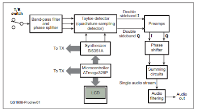
Here is the bloc diagram of the QCX.  It is essentially a phasing rig, using the same principles as my venerable HT-37 transmitter and my version of KK7B's R2 receiver: 


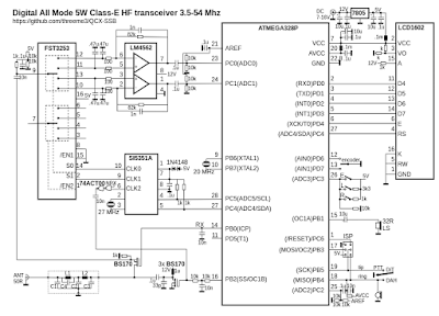
Yesterday Paul VK3HN sent me the schematic of the new multi-mode, multi-band version:  

Notice how different it is.   I thought that perhaps the new rig would keep something of the I-Q circuitry of the QCX, but it does not.  This is not a criticism, just an observation.  

But here is something that harks back to a topic we've been debating on the blog and podcast.  Notice that the top diagram is a bloc diagram.  There is a lot of circuitry in most of those boxes -- lots of resistors, capacitors, inductors, and transistors.   There is a schematic diagram under that bloc diagram.  But look at the second diagram.  While it looks like one, that one is NOT a bloc diagram. That IS the schematic diagram.  Most of the circuity has been sucked into the chips.  

While many will prefer the rig described by the second diagram, I remain an HDR guy, and don't really like seeing the circuitry disappear into the ICs.  But, to each his own.  This is all for fun.  Congratulations to the guys working on the new rig. 


Friday, May 22, 2020

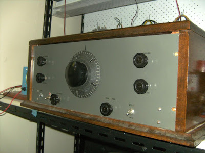
I,Q, and HRO: VK2BLQ's Phasing Receiver with an HRO Dial


I had occasionally fantasized about connecting Armand's HRO dial to the rotary encoder of an Si5351, but I think this was more of a nightmare than a fantasy.   I don't think Stephen VK2BLQ went this far -- I suspect that his HRO dial was connected to an analog VFO.  But still, the combination of HRO with I&Q seems a bit edgy...  FB Stephen.  Please send us more info on this amazing receiver. 
  
Hi Bill,

Hope you are safe there with the bad weather.

Recently you  mentioned HRO dials and the need to build a radio around one and Pete has been discussing phasing SSB; attached photo is a phasing receiver on 80 and 40 m, a combination of both HRO and IQ that I built many years ago, and thanks to Pete I shall get it running again.

And Bill, like you I am from the IGY of 1958 and retired with more free time on my hands.

Best regards to you and your family, especially young Billy.

Stephen,

VK2BLQ

Monday, May 18, 2020

Homebrew Az-El Satellite Antennas from the Philippines and Australia


https://nightskyinfocus.com/2020/05/18/diy-satellite-tracker/

DU1AU is way ahead of where I was when I was working with Low Earth Orbit satellites.   I just aimed the antenna about 45 degrees up from the horizon,  and spun it around with a TV rotator with me --not the computer -- as the controllers of the rotator.  In essence I did the AZ manually and completely ignored the EL.  This design moves the antenna in Azimuth and Elevation, and has the computer control the movements via an Arduino.  FB. 

DU1AU points to the work of VK3FOWL and VK3YSP.   Their site has very detailed info on how to build several versions of this kind of Az-El rotator: 

https://www.sarcnet.org/rotator-mk1.html

This Az-El project represents a great opportunity to move beyond hand-held satellite antennas,  and beyond my Az-only manual approach.   It also give us a way to bring some real homebrewing into a part of ham radio that has come to be dominated by commercial equipment. There are some Arduinos and some lines of code, some motors and some metal work.  Great stuff!   


Tuesday, March 31, 2020

Quarantine Rig: VK3YE Resurrects an Old BITX Project


I think we should start calling these "Quarantine Rigs."  Many of us are pulling off the shelves rigs that we started a while back but then put aside.  Now, with the pandemic,  we have the time (and the need!) to work on them.  

I like Peter's BITX receiver video, especially the part in the beginning where he wipes the grime and oxidation off the long-neglected copper-clad board.  

Follow Peter's lead:   Pull those old projects off the shelf.  Get them going.  Now is the time.  SITS!  Melt solder and flatten the curve. 

Thanks Peter.     
Designer: Douglas Bowman | Dimodifikasi oleh Abdul Munir Original Posting Rounders 3 Column