Just go to http://soldersmoke.com. On that archive page, just click on the blue hyperlinks and your audio player should play that episode.
http://soldersmoke.com
You have long been one of the leading gurus on DSB. I remember absorbing all the info I could from your website when I was getting started in DSB back in 2001.
It's great that you found the article about DSB with inverted audio. It would be very cool to build a transmitter with the inverted audio, then confirm that it could be received with a direct conversion receiver without distortion.
The incompatibility of DSB TXs and DC RXs seems like a very cruel trick of nature. There are only a few people in the world who think about this, and most of them are in the comments section of your YouTube video! An elite group indeed.
Back in 2015 your review of a DSB rig got me thinking about this incompatibility: https://soldersmoke.blogspot.com/2015/07/peter-parker-reviews-dsb-kit-and.html
It is easy to see how a slight frequency difference between TX VFO and RX VFO would cause a lot of distortion, but similar distortion would be caused by a phase difference between the two VFOs. AM SW Broadcast receivers try to minimize the effects of fading by using an internal oscillator to replace the wavering carrier -- but they have to have it exactly on frequency and locked in phase with the distant station's carrier. I have a little Sony portable that has this "synchronous detection" circuitry. It is a complicated task and I don't think you could do it with the highly suppressed carriers of our rigs. Inverted sidebands to the rescue!
Thanks for the great video and all the tribal knowledge.
I've been having a lot of fun with the Lafayette HA-600A receiver that I picked up earlier this month. Adding to the mirth, I noticed that on SSB, the signals sound a bit scratchy, a bit distorted, not-quite-right. (I'm not being facetious; this is an interesting problem and it might give me a chance to actually improve a piece of gear that I -- as a teenager -- had been afraid to work on.)
Before digging into the circuitry, I engaged in some front panel troubleshooting: I switched to AM and tuned in a strong local AM broadcast signal. It sounded great -- it had no sign of the distortion I was hearing on SSB. This was an important hint -- the only difference between the circuitry used on AM and the circuitry used on SSB is the detector and the BFO. In the AM mode a simple diode detector is used. In SSB a product detector and BFO is used. The BFO sounded fine and looked good on the scope. This caused me to focus on the product detector as the culprit.
Check out the schematic above. Tr-5 is the product detector. It is really, really simple. (See Einstein quote below.) It is a single-transistor mixer with BFO energy going into the base and IF energy going into the emitter. Output is taken from the collector and sent to the audio amplifiers. (A complete schematic for the receiver can be seen here: https://nvhrbiblio.nl/schema/Lafayette_HA600A.pdf )
I had never before seen a product detector like this. One such detector is described in Experimental Methods for RF Design (page 5.3) but the authors devoted just one paragraph to the circuity, noting that, "We have not performed careful measurement on this mixer." The lack of enthusiasm is palpable, and probably justified.
To test my suspicion that the product detector is the problem, I set up a little experiment. I loosely coupled the output of a signal generator to the IF circuitry of the HA-600A. I put the sign gen exactly on the frequency of the BFO. Then, I switched the receiver to AM, turning off the BFO and putting the AM diode detector to work. I was able to tune in the SSB signals without the kind of distortion I had heard when using the product detector.
So what do you folks think? Is the product detector the culprit? Or could the problem be in the AGC? Should I start plotting a change in the detector circuitry? Might a diode ring work better?
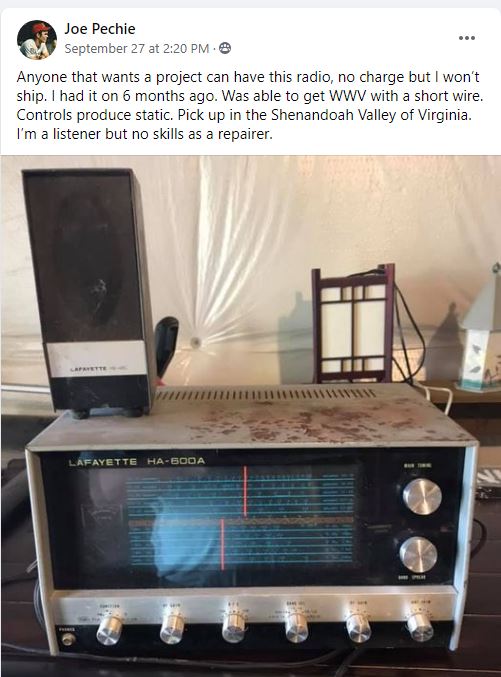
So on September 27,2020, I was sitting quietly in my shack, perusing the postings on various radio-related Facebook groups, when suddenly I saw it: my very first shortwave receiver, the magic box that had put me firmly on the path to amateur radio, the Lafayette HA-600A. Joe, the owner, was offering it FREE to anyone willing to pick it up at his home in Virginia's Shenandoah Valley. Holy Cow! I was scheduled to drive through that very valley later that week. A message was sent and the deal was done. CLEARLY THE RADIO GODS HAD SPOKEN (TRGHS).
Sure, the cabinet looked a bit rough, but I had high hopes for this receiver. A while back I had -- in a similar fit of nostalgia -- bought what had been advertised as a Lafayette HA-600A on e-bay. But it turned out to be a Lafayette HA-600 (no A). I immediately noticed a big difference in performance. That was NOT the radio that I remembered, not the receiver that had carried HCJB and Radio Moscow to me. Joe was clearly offering the A model.
A few days later I was in Joe's front yard for the hand-off, and a few days after that the HA-600A was on my bench.
I quickly realized how little I knew about this receiver. Mine was a Christmas gift, probably in 1973. (A few days ago I talked to my mom and thanked her for driving all the way to New Jersey to get this receiver for me.) I was so taken with this thing that I feared doing something -- anything -- that might mess it up. I lived in fear, for example, that some sort of freak mid-winter lightning bolt might destroy it. I covered it with a towel each night lest dust encumber its "jeweled movements." Obviously I was just not inclined to crack open the case and have a look around. So I didn't, and the receiver remained pretty much an appliance for all the time I owned it. (I eventually sold it on consignment at Electronics 59 in Spring Valley, New York. The proceeds probably went toward the purchase of a much better Drake 2-B receiver.)
I downloaded the manual and familiarized myself with the receiver: It is a single conversion superhet with a 455 kc IF. It is all solid state with no ICs -- all discrete transistors and diodes. The manual claims it has a mechanical filter. I kind of hoped for something like a Kokusai mechanical filter, but it turns out that the filter was really ceramic, not mechanical. Bummer.
The thing fired up right away and was inhaling on the correct frequencies. I noticed immediately that (as Joe had indicated) some of the controls were scratchy. I also noticed that the ganged band selection switch was intermittent and required some jiggling to get it to work properly. A few squirts of Deoxit D5 took care of all that. There seemed to be a bit of dirt in the main tuning capacitor, but I think I managed to blow that out using a can of Dust-off. I was quickly listening to the SW broadcast stations, and to radio amateurs on 75 and 40 meters.
Out of curiosity, I compared schematics of the HA-600 and the HA-600A. There was indeed a big difference -- the front end of the 600 lacks a lot of the RFA amplification circuitry of the A model. That's probably why is seemed so deaf and so different from what I remembered of the A model.
There is really not a lot to do on this receiver. I'll get some paint to fix up the top cover. I may check the alignment. But this single conversion receiver is so simple that alignment would be quite easy. In many ways this receiver seems like a solid state analog to the Hammarlund HQ-100, but without the clock, and without the regeneration circuitry. The dial lacks the exotic station locations (Java!) that make many of the older receivers so much fun. I guess this is an indication that this receiver was aimed more at amateur radio operators than at shortwave listeners ( I was both). I wonder how the ham band-only HA-800 compares to the HA-600A?
I could pair this receiver up with a DX-40 transmitter that I have on the shelf and I'd be most of the way toward re-creating my novice station. Anyone have a Globe VFO Deluxe? That would complete the setup.
Thanks very much to shortwave listener Joe Pechie for providing what is, for me, a very meaningful piece of gear.
I'm more of a single conversion guy myself, but in working with the DX-390 I came to appreciate the benefits (especially regarding image rejection) of the double conversion technique. While working on the DX-390, I discovered that the BFO control on the front panel DOES NOT change the BFO frequency. It was fun to try to figure out why the designers did it this way. It does make sense once you consider the limitation imposed by that PLL main tuning oscillator that only moves in 1 kHz steps. I hope the video explains things. Here is the drawing I used in the video:
And here is a drawing that shows how a single conversion superhet with a fixed or switchable (usually crystal-controlled) BFO works:
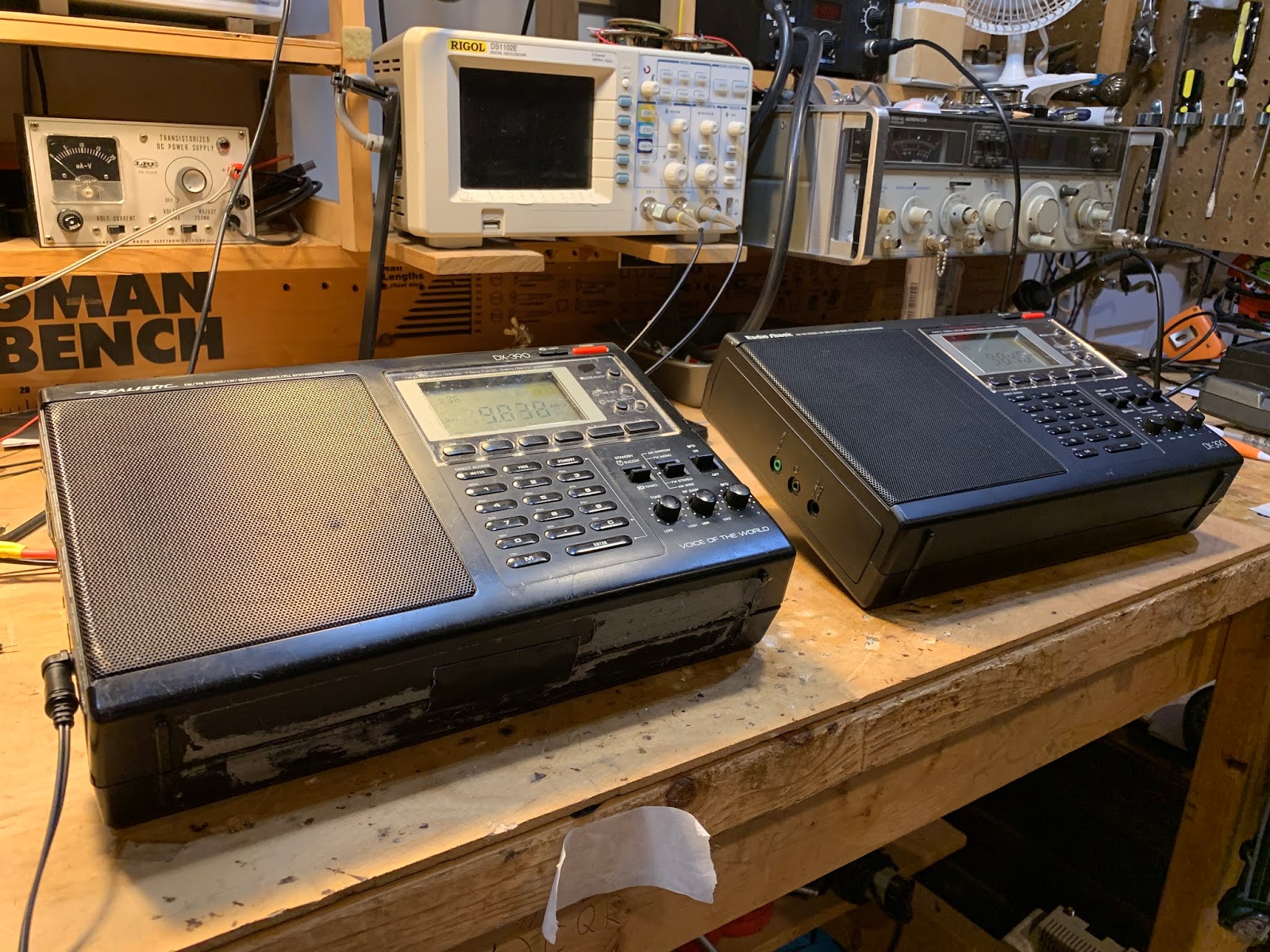
Earlier this month I did a blog post on my repair of a broken DX-390:
I've had this Radio Shack DX-390 portable receiver since the early 1990s. I bought it when I was in the Dominican Republic. It accompanied me on some interesting trips to the Haitian border, and on one very memorable 1994 trip to the Haitian capital. I have made some CW contacts with it serving at the inhaler.
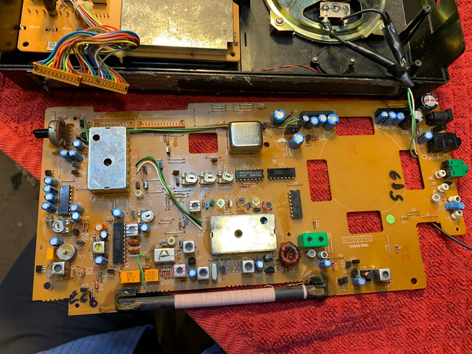
Click on the diagram for a better view. It is a dual conversion superhet. First IF is at 55.845 MHz. There is a big 90's era IC-based PLL oscillator that runs from 55.995 to 118.7 MHz -- The main tuning dial moves this oscillator. Second IF is at 450 kHz. There is an oscillator at 55.395 that takes the signal down to 450 kHz. Selectivity (not a lot) is provided by ceramic filters. Finally there is a product detector and a 450 kHz oscillator that produces the audio. While there are many mystery chips in this receiver, there is also a lot of discrete-component analog circuitry in there -- it is kind of a pleasing mix.
DX-390 Main Board. Note kludged toroidal replacment for L10 (just above ferrite antenna)
The old DX-390 suffered a lot of wear and tear. The case is very beat up. The most serious problem was that at some point, probably on a cold, dry, winter day in Virginia, static electricity took out the FET in the receiver's front end. I made a half-hearted effort to fix it, but it never really worked properly. I occasionally found myself thinking of this receiver. I spotted one on e-bay not long ago, and bought it. This newer one was in very nice shape. But that old one was kind of staring at me from the corner of the shack. "C'mon radio man," it seemed to say, "can't you fix a shortwave receiver?" So this week I took up the challenge. First the FET. I had kludged an MPF102 in there, but that didn't seem to work well. Internet fora seemed to think that a J310 would do better, so I installed one of them -- it did seem to work better. (Note: Pete Juliano likes J310s -- TRGHS.)
Kludged in J310. And two sets of back to back diodes
During my earlier repair effort I had apparently destroyed the front end output transformer (L10) but I discovered that I had replaced this with a toroidal transformer. It still worked, so I left well-enough alone. I was pleased that the old receiver was receiving OK, but there was a problem: The "BFO" control wasn't working. The BFO would come on, but turning the BFO control did not vary its frequency. At this point I discovered that while there are many copies of the DX-390 service manual and schematic on the internet, all of them have seriously degraded copy quality right around the parts of the circuitry that I needed to study. Sometimes Murphy overpowers the Radio Gods. It took me a while to get a useful schematic of the BFO control mechanism. BFO is a bit of a misnomer here: the control actually shifts the frequency of the 55.395 MHz oscillator that drives the second mixer. See Block diagram above). There is a varactor diode in the base circuit of a BLT oscillator circuit. Turning the BFO control varies the voltage going to the varactor thus causing the oscillator frequency to slide up and down. But mine wasn't moving. And that was a problem. So I dove right in, trying to figure out why it was oscillating, but not shifting in frequency. At this point I discovered that I too am afflicted with the disease that Pete Juliano suffers from: Fat Finger Syndrome. That BFO control circuit has a nice big 100k pot, but all the fixed resistors and caps were surface mount and SMALL. As I poked around trying to troubleshoot, I managed to make things worse. It turned out that the lead carrying 6 volts to the BFO control circuitry had broken. But before I discovered this, I managed to do all kinds of damage to the board. I lifted two PC board pads (I should have turned down the temperature on my soldering iron). Then, when I tried to fix this, I managed to put a solder bridge across two parts of the circuit that definitely should not have been connected. This resulted in a bizarre BFO situation. From the center position, turning the BFO to the left OR TO THE RIGHT would move the BFO in the same direction. So I could tune in an SSB station by turning to the right, or by turning to the left. That was just not right.
Lifted solder pads. And small wires that now bridge the gaps
Uffff. It took me a while to find that fault. While trying to figure this out, I built the circuit in LTSpice just to see what it was SUPPOSED to be doing. This helped. Eventually, through careful inspection with magnifying goggles, I found a solder blob, and removed it. Now all was right with the universe. Even though I had caused most of the trouble, it was still quite satisfying to fix it. Some additional observations on the DX-390. -- It really is a Sangean ATS-818 in disguise. Just look at the marking on the PLL board. If you can't find a decent DX-390 schematic, just use an ATS-818 schematic.
ATS 818 marking along the bottom (green) part of the PLL board
-- The service manuals on these receivers are quite good: the include bloc diagrams, detailed alignment instructions, and even voltage charts for all the chips and transistors. Impressive and useful. -- The static discharge vulnerability is hard to understand. There is so much cool circuitry in these receivers, why not add four simple diodes? Not wanting to repeat this saga, I went in and put two sets of back-to-back small signal diodes in each receiver: one set on the telescoping antenna, and other at the input for the external antenna. Curiously, on the newer receiver, it looks like a previous owner had gone in and tried to address this vulnerability -- but he did a very incomplete job. He just put ONE diode between the external antenna input and ground. I had always thought that two diodes back to back would give you good protection from static discharge. And I don't think that single diode protects the front end in any way from discharge coming in from the telescoping antenna.
This was a good project. I got more familiar with general coverage dual-conversion receivers. And I got reacquainted with an old receiver that I liked a lot. Both receivers could probably use some alignment. I'll take that up next.
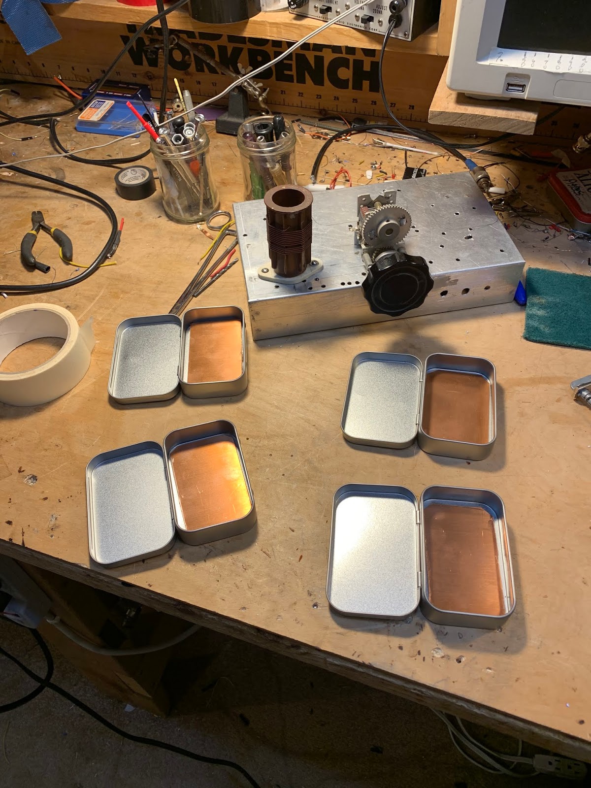
A while back Fred KC5RT sent me a nice collection of parts, including some 6 MHz crystals. I had been thinking of making a converter to put ahead of my Q-31 receiver. When Fred's 6 MHz rocks arrived, I knew that The Radio Gods Had Spoken (TRGHS). I found some NE602 chips in the junk box. I used an Altoid-sized box for the case. The toroids are from W8DIZ. I use trimmer caps from KC5RT to resonate the input and output circuits. Hooray! Now I can listen to 75 Meter AM on the Q-31. I may have to build a transmitter to go with this contraption. Thanks again Fred.
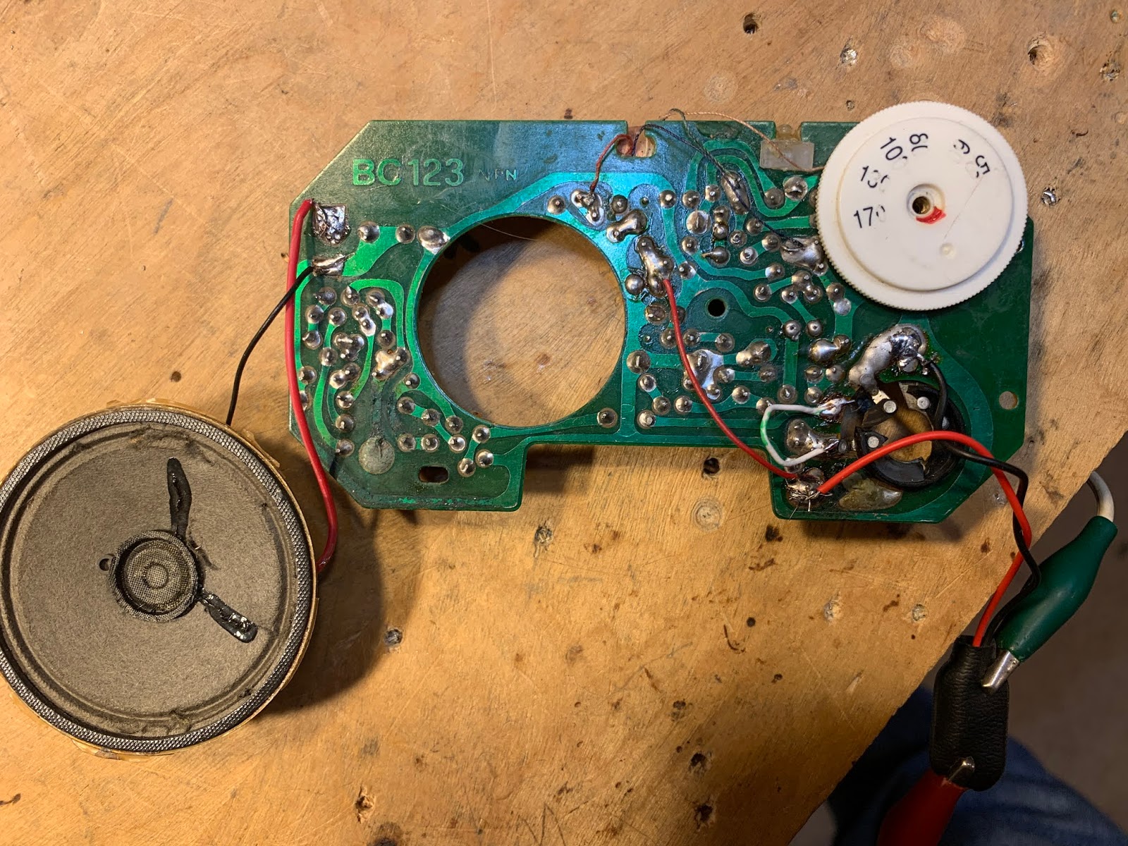
One of the great things about having a "miscellaneous" box in an otherwise well-ordered junk collection is that rummaging through that box will often send you off on fun and interesting radio adventures. I was rummaging yesterday and I came across the guts of the little AM radio that used to be mounted on my bicycle handle bars. I last mentioned this in 2011 :
I was just about to cannibalize this board. The IF transformers were almost certainly at 455 kc and I could use a few of those. But then I started thinking and Googling and trying to figure out the circuit. That all led me this the site that provided the diagram below:
Six transistors, four transformer cans, two audio transformers. Yea, that's pretty close to what I was seeing on my board. So of course I had to see if I could get it going. I hooked up a 9V battery. I connected the pot wiper connection directly to the connection at the top of where the pot had been (it had disintegrated). It works! It is inhaling nearby WFAX, Falls Church, Virginia.
You will notice that the transistors in the circuit above are PNP. I had assumed negative ground and had hooked the battery up accordingly. No smoke was released and the thing worked, so I guessed that I had assumed NPN correctly. Sure enough, perhaps aware of the PNP ancestry, the manufacturer had marked my board "BC123 NPN"!
The author of the book I linked to above dubbed this circuit the "All Japanese 6" -- an obvious allusion to the All American 5.
I see real potential in these AJ6s. A few mods to the front end and you could be shortwave listening, perhaps on 31 meters!
BTW: The space on my handlebars formerly occupied by that little AM radio is now taken up by a Bluetooth speaker that plays tunes streamed to my I-phone from Pandora as I make my way down the same old Washington and Old Dominion bike path. Progress.
Paul Taylor VK3HN's magnificent AM receiver was the inspiration for my Quarantine-31 Shortwave Broadcast receiver. Like Paul I decided to make use of ceramic filters at 455 kHz for selectivity. I started with the +/- 3 kHz filters that Paul used, but I found them kind of narrow for SW listening. So I went with some wider ceramic filters that Bruce KK0S had sent me. But I misread the specs that Bruce sent. I thought they were 10 kHz wide filters. I realized later that they were +/- 10 kHz -- really twice as wide as I needed. So I went back to Mini-Kits in Australia and got some +/- 6 kHz filters. 12 kc wide should be just about right, I thought.
The bandwidth was right, but I started noticing a problem: I could hear strong SW broadcast stations at two places on my dial. This brought to mind an admonition from R.A Penfold, author of "Short Wave Superhet Receiver Construction" (1991 Babani Publications). He advised keeping a few standard 455 kc IF cans in the circuit because, he warned, the ceramic filters have spurious responses, spurs that the IF cans can help knock down.
Penfold was right. Look at the filter response curve on the right (above). There is a nasty spur at around 640 kHz. This was the cause of my problem. Here is why:
Suppose I was tuning Radio Marti's big signal on 9805 kc. My VFO would be running at 9350 kc.
9805-9350=455. Great, but...
With that spur at 640 kc, I could tune down to 9620 kc on my dial. My VFO would be running at 9165 kc.
9805-9165=640. Bad. That 640 kc difference product would make it through to my detector and AF amp. I'd have Radio Marti showing up in two places. I didn't like this.
I thought about putting a series LC circuit tuned to 640 kc at the output of the ceramic filter. This looked like a possible solution, but on the bench it looked like I would have trouble getting a circuit of sufficiently high Q.
So rummaging around in my junk box I found an old Murata CFM455B filter. This filter is quite broad, but it does not have the spur at 640 kc. I could use it as a kind of roofing filter just ahead of the +/- 6 kHz filter. Putting it there would allow me to avoid having to build additional matching circuits for the 455B filter.
+/-6kc filter upper left, 455B wide filter to the lover right.
I'm happy to report that this fix works. The 6 kc filter provides the needed selectivity, and the broader 455B filter knocks down the 640 kc spur.
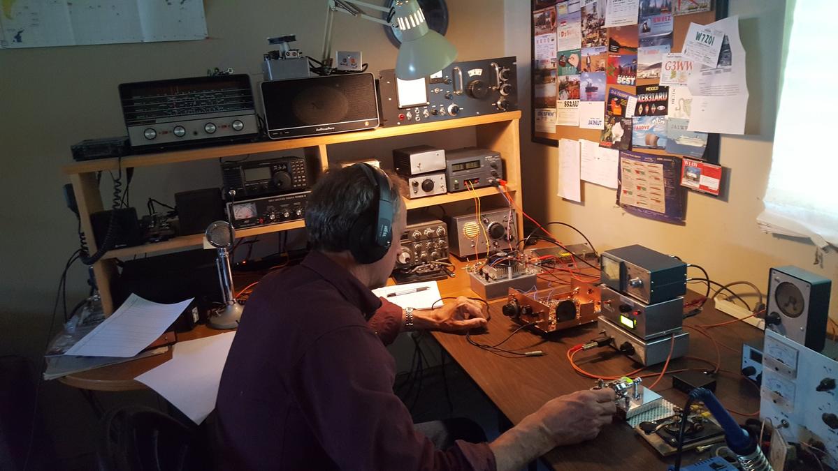
Dean KK4DAS asked me to speak to our local radio club, the Vienna Wireless Society. It was a lot of fun. I talked about my evolution as a homebrewer, some of the rigs I made, the moments of joy, and the tales of woe. You can watch the presentation in the video above. I was really glad to be able to explain in the presentation the importance of people like Pete, Dex, Farhan, Wes, Shep and even Dilbert. I was also pleased to get into the presentation the N2CQR sign that Peter VK2EMU made for me. Thanks Peter! Here is the URL to the YouTube video (also above): https://www.youtube.com/watch?time_continue=3414&v=VHSr-v4QO7Q&feature=emb_logo And here are the PowerPoint slides I used: https://viennawireless.net/wp/wp-content/uploads/2020/06/VWS-presentation-Rig-here-is-homebrew.pdf
This (above) is a general Shortwave Superhet receiver I built over the winter. I chose to go modular so I could interchange some of the modules and make easy repairs and changes to the circuits. I used discreet components and only 2 integrated circuits. I built a Colpitt's buffered oscillator which is remarkably stable, a Gilbert Cell Double Balanced Mixer, a high pass filter to filter out local AM broadcast station. The IF chain uses an old classic collins 455 khz mechanical filter amplified by a J310 feeding into an MC1350P IC... It's using 2 germanium diodes as a detector feeding into an LM386 output amp. It's very, very selective and sensitive. I added a 455 khz BFO (lower right in pic) the other day to tune in SSB and CW. This has been a fun experiment.
I heard this program this morning on my Q-31 receiver. It was on WRMI 9955 kHz at around 1330 UTC. It reminded me a lot of the DX listening program of HCJB. Good stuff. You can listen to the programs on-line at: https://awr.org/program/engmi_wav/
Almost done. A few odds and ends remain, but now I have all the circuitry in their boxes. As I was taking my walk the other day I was thinking of how I didn't have to build a BFO for this superhet. That's because the signals coming in on this rig bring with them their own BFO signal (the carrier).
Today I added two additional stages of IF amplification. This added 30 db to the receiver's total gain. That helped a lot. I also discovered that Germanium (1N34A) diodes work a LOT better as AM detectors than do silicon diodes. This receiver is starting to sound decent. Currently listening to the VORW program on WRMI Miami.
I've been recording short videos on my progress with the Q-31 Shortwave AM Quarantine Receiver. Yesterday was a bit of a milestone -- I put five of the six sub-assemblies together and did some testing. You can see the video above. All the other videos are on my YouTube site: https://www.youtube.com/user/M0HBR Please subscribe and give me a "thumbs up." SITS! Stay in the shack! Flatten the curve. Hang in there. 73 Bill
I've been making some short, stage-by-stage videos of my Q-31 receiver project. So far I have seven videos. They are here: https://www.youtube.com/user/M0HBR/videos Please subscribe to my YouTube Channel. And give me some "thumbs up" if you like the videos. Thanks. SITS! FlattenTheCurve! 73
My work on the S-38Es, on the HRO-dial receiver, on the Mate for the Mighty Midget, and on various mechanical filters has caused me to think (once again) about why we ended up with 455 kHz as the IF frequency for so many radios. I've heard many explanations for this, but unfortunately I've forgotten the explanations and lost the sources. I started digging into this again today. I found the below e-mail from Al N3FRQ on the Boatanchors mailing list (2008). I contacted Al to find out if he had learned anything else on this topic. He has not. So if anyone out there has answers to Al's questions, or anyother info that would shed light on why they went with 455, please let us know. -------------------------------
Every so often the question comes up: Why are all the IF’s 455 KHz? I’d
like to get an article together that solves this riddle while the people
who know are still with us. I know parts of the story, but I need help
with a couple of issues.

There are two major consideration is the choice of the intermediate
frequency used in a superheterodyne receiver. The lower the frequency,
the easier it is to attain high selectivity. Also, in the early days,
before tetrode and pentode tubes, it was easier to achieve a high degree
of amplification at lower frequencies. Conversely, a higher IF frequency
results in better image rejection.

Early superhets had the IF at 100KHz or lower in order to get adequate
gain from the available triode tubes. They suffer severely from
“two-spot tuning” (images). By the early 1930’s, broadcast set had
settled in at 175KHz, and automobile receivers would later adopt 262KHz
as a standard.

The advent of the short-wave craze, and multi-band broadcast receivers
dictated a higher IF frequency to achieve adequate image suppression on
the short-wave bands. The broadcast band occupied 550-1500KHz at this
time, and the designer encounters sever problems if his radio tunes
across it’s own IF. Some shortwave sets used 1600-1700KHz for better
image rejection, but one couldn’t go higher if the 160-meter ham band
(1800-2000KHZ) was to be covered. Most multi-band receiver settled in
near 450KHz, a comfortable distance from the first broadcast channel at
550KHz.

Questions:

Odd multiples of 5KHz, 455, 465, etc., were usually chosen so that the
image of the carrier of a broadcast-band station could be zero-beat with
the carrier of the station being tuned to achieve minimal interference.
(This assumes 10KHz channel spacing. Did the Europeans (9KHz) do
something else?)

The Radiotron Designers Handbook, Third Edition, p. 159, states “A
frequency of 455 Kc/s is receiving universal acceptance as a standard
frequency, and efforts are being made to maintain this frequency free
from radio interference.”

(1) Do FCC and international frequency allocations reflect this?

(2) I’ve heard the term “Clear-Channel IF.” Can anyone cite references?

(3) At lease one news group posting claims that broadcast frequencies in
a particular market are assigned to prevent strong inter-modulation
products from falling near 455KHz. Is this factual? Need reference.”

(4) Was this (3) at least part of the reason for “Radio Moving Day” in
1941? See: http://www.dcmemories.com/RadioMovingDay/032341WINXFreqChange.jpg

(5) Many National Radio sets used a 456KHz IF’s and I think I remember a
437 somewhere. Why? Are there different considerations for short-wave CW
operation?

Further input, corrections, and elaborations are greatly appreciated.
Scolarly reference will be looked upon with great favor.

Regards,
Al

--
Al Klase - N3FRQ
Flemington, NJ
http://www.skywaves.ar88.net/
It is always a pleasure to see a new video on Mr. Carlson's awesome YouTube channel, especially in these days of Staying-In-The-Shack (SITS). Obviously Mr. Carlson is doing his bit in this area. FLATTEN THE CURVE! Thanks OM! My recent bout of S-38E madness has peaked my interest in the All American Five design, so this March 10, 2020 video was especially interesting to me. Mr. Carlson puts out so much great tribal knowledge. I didn't know about "rounder" resistors. I didn't know that you have to be careful not to short out (to the IF can case!) the 455 kc transformers. I really like his approach to dial cord restoration. Mr. Carlson's discussion of the adjustment of the front end tuner circuit on this broadcast band radio was very interesting. Unlike the S-38 radios, there are no front end coils being switched in as you change bands. In fact, it appears that that big coil/antenna inside the back cardboard piece IS the front end coil. This discussion has caused me to question my front end alignment technique for the S-38E. Did I have an appropriate antenna or antenna substitute across the antenna terminal when I set the peak on the input LC circuit? I will check on this. Hooray! One more thing to do during the COVID-19 SITS period. UPDATE: I checked on this using the test set up described in an earlier post, but this time with my antennas connected. First with a 40 meter dipole, then with my 130 foot doublet, then with a 50 ohm dummy load I was still able to see the resonance dips at exactly where I wanted them to be. My favorite bit of Carlsonian wisdom from this video? Mr. C's confirmation that some hum in All American Five receivers IS NORMAL! (This may be too much for the folks who find normal band noise to be offensive.)
Be sure to check out the blog of Dean KK4DAS. He is a new homebrewer who is having great success with one of Pete Juliano's ingenious SSB designs. Dean has a video of his receiver working -- AL FRESCO -- as construction on the full transceiver proceeds. This is amazing. Just a short time ago Dean was taking his first steps as a homebrewer with his version of the Michigan Mighty Mite. He has followed the advice of the Tribal Wizards and has proceeded slowly, step by step, stage by stage, gaining the experience that has allowed him to actually build a superhet receiver and be on the verge of completing a full SSB transceiver. Lots of inspiration to be found on Dean's blog. Check it out: https://kk4das.blogspot.com/2020/03/dean-kk4dass-furlough-40-ssb-rig.html
The COVID-19 emergency is a good time to look around the shack for projects you have been meaning to take on but didn't have the time for. We have the time for them now! When I first built my HRO-dial receiver (using an HRO dial given to me by Armand WA1UQO and an enclosure from Tim KI6BGE) my hope was to have the 40 meter ham band and some shortwave broadcast bands. But it didn't work out that way. I had trouble getting an AM detector to work properly, and I had a hard time getting a sufficiently broad filter to work right. I ended up adjusting the VFO so that the receiver would cover only the 40 meter ham band. My recent S-38E adventures and a video from VK3HN have alerted me to the nice programming that is now on the shortwave broadcast bands (I really like WRMI's afternoon rock music program). So I decided to take another shot at getting this receiver to cover SW BC frequencies. When I built this receiver, I made the front-end bandpass filter tune-able. There is a two section variable cap behind that "Pre-selector" control you see on the front panel. That lets me tune two loosely coupled LC circuits from about 5.5 to about 8 MHz. So without any mods to the front end, I could cover the 49 meter band (5.9 -- 6.2 MHz) our 40 meter band, and the 41 meter band (7.2-7.5 MHz) Here is how I do it: For 49 meters: I now have the VFO set to run from 6.34 MHz to 7.120 MHz. The IF is .455 Mhz. So to get down to the lowest frequency in the 49 meter band, I tune that front end preselector down to that frequency (variable cap in filter almost fully meshed). Then I take the VFO down to 6.355 Mhz. I take the difference frequency out of the mixer -- .455 MHz. For 40 and 41 meters: I just tune the pre-selector to this range (variable cap about mid-range) and tune the VFO accordingly. For a signal at 7.5 MHz, for example, I put the VFO at 7.045 MHz. 7.5 - 7.045 = .455 Mhz. Note: There is no sideband inversion in this case -- this is important because 40 meter SSB is lower sideband. The Kokusai mechanical filter that Pete N6QW gave me is a lower sideband filter. I have my BFO set at the right spot relative to the filter passband for LSB. As you can see, I just tune to the "image frequencies" with the preselector. This gives me double the frequency coverage. As for the filters, well Pete's Kokusai filter works great on 40 SSB. My problem was, ironically, getting a filter that was broad enough to let AM sound good. I concocted a filter using old 455 kc IF cans, but I wasn't happy with it. Paul VK3HN used a ceramic .455 MHz filter that was 6 kHz wide at 6 db down. I ordered some from Australia. That should have been wide enough for AM, but I had gotten spoiled by the very WIDE bandwidth of my S-38Es (no real filters at all, just the two 455 kc IF cans). At this point The Radio Gods interceded. Bruce KK0S heard me talking about this on the podcast and kindly sent me some 10 kHz .455 kHz filters. Now we're talking! I put one of them in this receiver and AM started sounding as good as it does in my S-38E. BTW -- a look at NA5B's WebSDR receiver shows that most of the SW broadcast stations are running at 10 kHz wide. See video below:
Finally, I had to get a decent AM detector going. The SBL-1 product detector I have in there works great, but I had tried several AM detectors and none of them worked well for me. This was puzzling -- it should be so simple, right? Just a diode. But I would get weak and/or distorted audio. I realized that I really needed was something that looked to the rest of the circuitry like an SBL-1, but with just a diode and an RC filter section instead of the SBL-1's diode ring. I ended up using a small 455 kc IF transformer that Michael Rainey (AA1TJ) had sent me a long time ago. My detector looks like this:
It works great. During the day I can hear the Toronto CFRX talk-radio station that simulcasts with 1 kW on 6.07 MHz. In the evening I her WBCQ and many other stations on 41 meters (see videos). And of course I am ready to use it for amateur AM signals on the high end of the 40 meter phone band.
There is a lot of soul and friendship in this receiver:
-- HRO dial from Armand WA1UQO
-- Aluminum box from Tim Sutton KI6BGE
-- Mechanical Filter from Pete N6QW
-- IF transformer from Michael AA1TJ
-- Ceramic filter from Bruce KK0S
-- 10k pot in the detector from Thomas KK6AHT
-- Inspiration and ideas from Paul VK3HN
-- Many parts from Jim...
But you know, I find myself thinking that there are many stations I like on the 39 meter band. I think it might be best to build a separate receiver for those frequencies. Maybe throw in 30 meters. Hmm, let me see what's in the junk box...
"SolderSmoke -- Global Adventures in Wireless Electronics" is now available as an e-book for Amazon's Kindle.
Here's the site:
http://www.amazon.com/dp/B004V9FIVW
Re: EF JOHNSON HISTORICAL TREASURE CHEST
-
The problem with many of Johnson's original manuals was that many of the
page sheets were printed on acidic-type paper. After 60 plus years, sheet
color tu...
Why AM Radio in EVs Could Cost Billions
-
Many thanks to SWLing Post contributor, Dennis Dura, who shares the
following video via the Geerling Engineering YouTube channel: Description:
The Center f...
Moorabbin Radiofest
-
The Moorabbin RadioFest was a terrific show this year. The turnout looked
good to me although I'm told it was down on past years.It was great to see
a vend...
Help wanted for IRTS VHF/UHF management team...
-
The *Irish Radio Transmitters Society* (IRTS) is the national association
for radio amateurs in Ireland. They had this news item on the 12th of May
2024....
Broadcast Band AM Radio
-
See the YouTube series for more information:
http://www.youtube.com/c/CharlieMorrisZL2CTM
Buffer Amplifier
Low Pass Filter
IF Amplifier, Infini...
An Inline RF Step Attenuator for QRPp Work
-
I don’t need to explain the attraction of low power operation; if you’re
reading this, the chances are that you are already a convert. I’ve been
operating ...
A 51S-1 Restoration Story
-
I came across my Collins 51S-1 in a big junkyard in Ankara, Turkey around
2012. It was in a pile with a lot of other electronic scrap, probably from
one o...
New QRP Cluster Online From OM0ET and OM6APN
-
By DX EXPLORER
DX EXPLORER
Paul OM0ET and Peter OM6APN recently launched a new cluster dedicated to
QRP operations. Have a look and I hope you will enjoy...
3D Printing The Hadley 114mm Newtonian Telescope
-
Yes, we’re building a 3D Printed Newtonian Telescope called Hadley. It’s
being printed in PETG and in the video below, I give a quick tour. My build
isn’...
3D printed project boxes
-
I have been busy with some other things that have kept me away from
electronics projects for quite a while. Now I can get back to them, but
realize I n...
Daylight Again – An all Analog Radio
-
What’s all this? In 10 seconds, A high performance, 7MHz, 5 watt SSB rig
Draws just 24 mA of current 90 dB dynamic range, 80 dB close-in dynamic
range 3D ...
Adding Enclosure to your sBitx Boards Order
-
The early buyers of the sBitx board set who bought it for $270 USD might
want to also add the enclosure (box) for in the kit. What you will now get
is a f...
Digi-chirp! Digital synthesis of ‘nostalgic’ CW
-
The bottom ends of 80, 40 and 20m are not what they used to be. For
starters, the busiest part is the digital segment where computers talk to
computers – l...
-
A Simple Speech Processor
(For QRP/SSB Homebrew Transceivers )
Over the last few weeks I had been thinking to build a small AF speech
processor to add to...
A New Look for your uBitx!
-
Adding a "Cool Blue" Display to your uBitx!
The standard "green background" with black lettering frequently reminds me
that I suffer from Chronic seasickn...