
Podcasting since 2005! Listen to Latest SolderSmoke
Sunday, October 24, 2021
WA9WFA's Mate for the Mighty Midget 1966 QST Receiver

Tuesday, April 5, 2016
My Mate for the Mighty Midget Thermatron Receiver


Wednesday, December 11, 2024
Mike WU2D's Video on the SimpleX Super Receiver -- Part II
Another FB video from Mike WU2D.
But you know, I too find myself kind of opposed to front panel on-off switches. I power my rigs with small DC supplies. I just turn on the supply when I want to use one of the rigs. I don't have or need a switch on the front panel of the rig.
I especially liked Mike's use of the gate dip meter and, of course, the Q meter. FB OM.
Friday, November 12, 2021
Mate for the Mighty Midget with 6 kHz Ceramic Filter
Sunday, August 21, 2016
First Signals from the PA3GSV Mighty Midget Mate
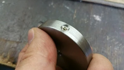
Obviously the Radio Gods (Spirits in the Sky) approve of Jan's work. How could they not? I can now see why he took the trouble to cut that hole in the sewer pipe cap that forms the large wheel on his homebrew reduction drive. But what are we going to see through that center hole Jan? What will the frequency readout be like?
----------------------
Hi Bill,
Wednesday, June 15, 2016
Jan PA3GSV's Amazing Mate for the Mighty Midget
Sunday, October 7, 2012
My Mate for the Mighty Midget
Al, W1UX, asked for a picture of the receiver that I used to listen to his dulcet tones this morning. Here you go Al. Here is an article on the project:
http://www.gadgeteer.us/erart.htm
Above is the Mighty Midget RX paired up with a DX-60 and a VF-1 (circa 1998)
Our book: "SolderSmoke -- Global Adventures in Wireless Electronics" http://soldersmoke.com/book.htm Our coffee mugs, T-Shirts, bumper stickers: http://www.cafepress.com/SolderSmoke Our Book Store: http://astore.amazon.com/contracross-20
Saturday, October 9, 2021
Recent Homebrew Projects from Jan PA3GSV (of "Mate for the Mighty Midget" Fame)
Recent talk of the Mate for the Mighty Midget receiver and Pete's PIMP SSB transmitter brought me back in contact with the work of Jan, PA3GSV. I took a look at his QRZ.com page and found that he has some projects that rival even his seemingly unbeatable MMM RX project.
Check it out for some real homebrew eye candy:
Monday, February 14, 2022
6EA8s in the Mate for the Mighty Midget, and WA9WFA Re-Builds a Heath HW-12
I reported to Scott and Grayson that I had finally gotten around to changing the three aging 6U8 tubes in my Mate for the Mighty Midget receiver. I replaced them with three more youthful 6EA8s. This switch really seemed to perk up the old receiver. I'm listening to 75 meters on it right now.
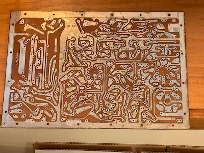
Speaking of 75 meters, Scott sent me this picture of his latest effort: re-building a Heathkit HW-12. FB. This is a way of experiencing (or re-experiencing) the construction of a Heathkit. I did something similar, but much less complicated) with a Heathkit VF-1. Scott did a wonderful job taking this old rig apart. That PC board looks great (see photo below).
Scott's e-mail:
Hi Bill and Grayson, I’m glad to hear of your good results with the 6EA8’s in your MMMrx! I had similar results when I finally got rid of the 6U8’s with their iffy performance and went with the 6EA8’s. I did put a set of 6GH8A’s and tried it out, it worked, but I don’t have any data on performance improvements. After completing the outboard power supply and audio amplifier, I’ve taken a break from my MMMRx and it’s sitting there on the bench. I’ll get back to it in a while.
In the meantime I’ve started a new project where I’m re-kitting a Heathkit HW-12 eighty meter transceiver. I have completed the disassembly process including the pcb. I bought a Hakko vacuum desoldering iron for taking all (ALL) parts off of the pcb, and it’s bare now. I’m planning to start rebuilding this coming week. 73 Scott WA9WFA
Sunday, August 22, 2021
Joe Galeski's 1960 "IMP" 3 -Tube Filter SSB Transmitter, and the Spirit of SSB Homebrew
Here is another important bit of SSB history. In May 1960, Joe Galeski W4IMP published an article in QST describing his super-simple SSB transmitter. While Tony Vitale's "Cheap and Easy" rig was a phasing design, Joe came up with a filter rig. He built USB filter at 5775 kc. With it, he ran a VXO at around 8525 kc. This put him on 20 meter USB.
Here is the QST article: http://marc.retronik.fr/AmateurRadio/SSB/A_3_tubes_filter_rig_%28SSB%29_%5BQST_1960_5p%5D.pdf
In discussing how to put this rig on other bands, Joe got the sideband inversion question exactly right:
Monday, October 4, 2021
Scott WA9WFA's Mate for the Mighty Midget Receiver is WORKING! (Video)
Saturday, April 23, 2016
A Reduction Drive for the Mighty Midget's Mate Receiver
Sunday, July 10, 2016
Update: PA3GSV's Amazing Mighty Midget Receiver (video)
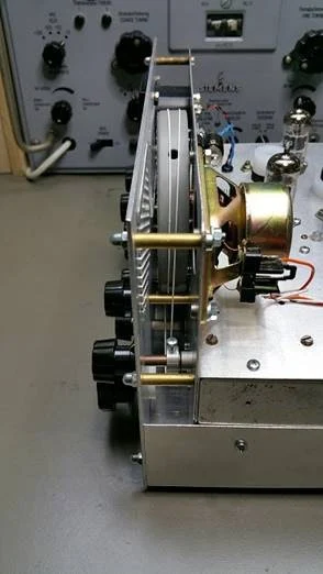
Jan sent me an amazing update on his Mate for the Mighty Midget Mk 2 receiver project. I'm really blown away by the skill that he brings to the mechanical phase of this project. This is a homebrew dial-string reduction drive using the end cap from a sewer pipe as the big wheel. Think about that. Amazing. Jan reports that with the mechanical work almost done, he is almost ready to start melting solder. FB Jan! Check out the video above and the photos below.
Saturday, October 29, 2016
DONE! Jan's AMAZING Mate for the Mighty Midget Receiver
For the lower end of 80m I had to add additional 47 pF next to the 47 pF trimmer caps, so there it is about 600-650 pF max!
Saturday, June 11, 2022
Putting the "Mate for the Mighty Midget" Back to Work -- With a DX-100 on 40 Meter AM
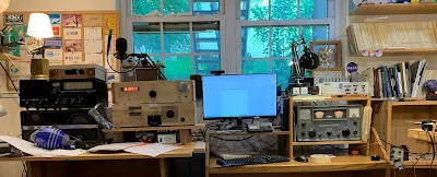
After working on it for a while I got so fond of my old Hammarlund HQ-100 that I moved it from the AM/Boatanchors operating position over to a more convenient spot right next to my computer. This left a big gap on the receive side of the AM station.
I briefly put my HRO-ish solid state receiver above the DX-100, but I'm afraid that receiver needs some work. More on that in due course.
I thought about putting my SOLID STATE Lafayette HA-600A atop the thermatronic DX-100, but this just didn't seem right. The Radio Gods would NOT approve.
So I turned my attention to the Mate for the Mighty Midget that I built in 1998 and have been poking at and "improving" ever since.
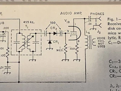
This receiver worked, but not quite right. It received SSB stations well enough, but when I turned off the BFO I could no longer hear the band noise. I wasn't sure how well the RF amp's grid and plate tuned circuits tracked. And I had serious doubts about the detector circuit that Lew McCoy put in there when he designed this thing back in 1966.
As I started this latest round of MMMRX poking, I realized that I now have test gear that I didn't have in 1998: I now have a decent oscilloscope. I have an HP-8640B signal generator (thanks Steve Silverman and Dave Bamford). I have an AADE LC meter. And I've learned a lot about building rigs.
FRONT END TRACKING
The MMRX has a tuned circuit in the grid of the RF amplifier, and another in the plate circuit of the RF amplifier. There is a ganged capacitor that tunes them both. They need to cover both 80/75 and 40 meters. And they need to "track" fairly well: over the fairly broad range of 3.5 to 7.3 MHz they both need to be resonant at the same frequency.
McCoy's article just called for "ten turns on a pill bottle" for the coils in these parallel LC circuits. The link coils were 5 turns. No data on inductance was given. Armed now with an LC meter, I pulled these coils off the chassis and measured the inductances of the coils. I just needed to make sure they were close in value. They were:
L1 was .858uH L2 was 2.709 L3 was .930uH L4 was 2.672
Next I checked the ganged variable capacitors. At first I found that one cap had a lot more capacitance than they other. How could that be? Then I remembered that I had installed trimmer caps across each of the ganged capacitors. Adjusting these trimmers (and leaving the caps connected to the grid of V1a and V2A, I adjusted the trimmers to get the caps close in value. I think I ended up with them fairly close:
C1: 63.77-532 pF C2 64.81 -- 525.1 pF
I put the coils back in and checked the tracking on 40 and on 80/75. While not perfect, it was close enough to stop messing with it.
DETECTOR CIRCUIT
I've had my doubts about the detector circuit that Lew McCoy had in the MMMRX. In his 1966 QST article he claimed that the circuit he used was a voltage doubler, and that this would boost signal strength. But I built the thing in LT Spice and didn't notice any doubling. And consider the capacitors he had at the input and output of the detector: 100 pF. At 455 kHz 100 pF is about 3500 ohms. At audio (1 kHz) it is 1.5 MILLION ohms. Ouch. No wonder years ago I put a .1 uF cap across that output cap just to get the receiver working.
Scott WA9WFA told me that by the time the MMMRX appeared in the 1969 ARRL handbook, the second "voltage doubling" diode was gone, as were the 100 pF caps. Now it was just a diode, a .01 uF cap and a 470,000 ohm resistor. I switched to the 1969 Handbook circuit (but I have not yet changed the 1 meg grid resister to 470k -- I don't think this will make much difference). Foiled again by a faulty QST article, again by one of the League's luminaries.
6U8s out, 6EA8s in
We learned that the 6U8 tubes originally called for by Lew McCoy are getting old and not aging well. So I switched all three to more youthful 6EA8s. This seemed to perk the receiver up a bit.
MUTING from the DX-100
My K2ZA DX-100 has a T/R relay mounted in a box on the back of the transmitter. When the Plate switch goes up, it switches the antenna from receiver to transmitter. The box also has a one pole double throw switch available for receiver muting. I put the common connection to ground, the normally connected (receive position) connect the ground terminal of the AF output transformer to ground -- it is disconnected from ground on transmit. The other connection (normally open) is connected to the antenna jack -- on transmit this connection ground the receiver RF input connection. These two steps mutes the receiver very nicely.
Replacing Reduction Drive
Over the years I have had several different reduction drives on the main tuning cap. I had a kind of wonky Jackson brothers drive on there that needed to be replaced. I put in a new one -- this smoothed out he tuning considerably.
Ceramic Resonator
I never could get McCoy's 455 kc two crystal filter to work right. So at first I made due with the two 455 kc IF cans. This made for a very broad passband. Then I put a CM filter in there. This was more narrow, but with a lot of loss. There may have been others. But the filter spot is currently held by a 6 kHz wide ceramic filter. This one is my favorite so far.
Digital Readout
When I was running the DX-100 with the Hammarlund HQ-100 I built a little frequency readout box. The box was from a Heath QF-1 Q multiplier (I am sorry about this). The readouts are in Juliano Blue and come via e-bay from San Jian. I now have it hooked up to the DX-100's oscillator. I haven't tapped into the MMMRX's oscillator yet.
Thursday, December 18, 2014
N5AB's Mighty Midget 40
Friday, June 17, 2022
SolderSmoke Podcast #238 -- SolderSmoke Shack South, Cycle 25, Chiquita Banana Radio, RCA, HQ-100, Mate Mighty Midget, Sony SWL RX , Mailbag
SolderSmoke Podcast #238 is available: http://soldersmoke.com/soldersmoke238.mp3
TRAVELOGUE:
Cathartic decluttering: Bill preparing for future winter travel to Dominican Republic. Will build SolderSmoke Shack South. Dividing everything up: Rigs, parts, tools, supplies, antennas, test gear. Everything.
PETE'S BENCH:










.webp)


