Podcasting since August 2005! Listen to our latest podcast here:

Podcasting since August 2005! Listen to Latest SolderSmoke

Showing posts sorted by relevance for query sideband Inversion. Sort by date Show all posts

Thursday, June 17, 2021

The Stubborn Myth about USB and LSB

It  has been repeated so often and for so long that many of us have come to believe it.  I myself believed it for a while.   Like many myths, it has a ring of truth to it.  And it is a simple, convenient explanation for a complex question: 

Why do ham single sideband operators use LSB below 10 MHz, but USB above 10 MHz? 

Here is the standard (but WRONG) answer: 

In the early days of SSB, hams discovered that with a 9 MHz SSB generator and a VFO running around 5.2 MHz, they could easily reach both 75 meters and 20 meters (True). And because of sideband inversion, a 9 MHz LSB signal would emerge from the mixer as an LSB signal (True), while the 20 meter signal would emerge -- because of sideband inversion -- as a USB signal (FALSE!)  That sideband inversion for the 20 meter signal explains, they claim,  the LSB/USB convention we use to this day. 

Why this explanation is wrong: 

There is a very simple rule to determine if sideband inversion is taking place:  If you are subtracting the signal with the modulation FROM the signal without the modulation (the LO or VFO) you will have sideband inversion.  If not, you will NOT have sideband inversion.

So, you just have to ask yourself:   For either 20 or 75 are we SUBTRACTNG the Modulated signal (9 MHz) from the unmodulated signal (5.2 MHz)? 

For 75 meters we have:   9 MHz - 5.2 MHz =  3.8 MHz    NO.  We are not subtracting the modulated signal from the unmodulated signal.  There will NOT be sideband inversion. 

For 20 meters we have 9 MHz + 5.2 MHz = 14.2 MHz.     NO.  No subtraction here.  No sideband inversion.   

So it is just arithmetically impossible for there to be the kind of happy, easy, and convenient  USB/LSB situation described so persistently by the myth. 

---------------------------------

We discussed this several times on the podcast and in the blog: 

https://soldersmoke.blogspot.com/2015/05/sideband-inversion.html

https://soldersmoke.blogspot.com/2012/05/usblsb-urban-legend-debunked.html 

This myth shows up all over the place: 

We see the myth here: 

http://n4trb.com/AmateurRadio/Why%20The%20Sideband%20Convention%20-%20formatted.pdf

Here the web site owner warns that this is "highly controversial."  Really?  Arithmetic? 

http://9m2ar.com/lsb7.htm

The myth is very old.   Here is a clip from a 1966 issue of "73" magazine: 

https://worldradiohistory.com/Archive-DX/73-magazine/73-magazine-1966/73-magazine-01-january-1966.pdf

Finally, to my disappointment, I found the myth being circulated by the ARRL, in the 2002 ARRL Handbook page 12.3: 


The fact that the Handbook attributed this to a desire to "reduce circuit complexity" by not including a sideband switch should have set off alarms.  We are talking about hams who built their own SSB rigs, usually phasing rigs.  A sideband switch would not have added significant circuit complexity. I think they could have handled it. 

It is interesting that earlier ARRL Handbooks do not repeat this myth.  I found no sign of it in Handbooks from 1947, 1959, 1963, 1973, and 1980.  And I found no sign of it in several editions of that great ARRL book "Single Sideband for the Radio Amateur." 

For my next homebrew rig, I will build a rig that DOES do what the myth promises.  I will have the SSB generator running on 5.2 MHz USB.  The VFO (out of an old FT-101) will be running around 9 MHz.  So for 75 meters we WILL be subtracting the signal with the modulation from the signal without the modulation:   9 MHz - 5.2 MHz = 3.8 MHz.   There will be inversion.  This 75 meter signal will be LSB.   For 20 we will just add the 5.2 MHz USB signal to the 9 MHz  VFO.  There will be no inversion.  We will have a USB signal on 20.   I'm thinking of calling this new rig "The Legend." Or perhaps, "The Mythbuster." 

Wednesday, May 6, 2015

Sideband Inversion


Joel Hallas, W1ZR, (aka "The Doctor") has an especially good column in QST this month.   He takes on a topic that has confused (and re-confused!) many of us: sideband inversion.  Simply put, if you have a single sideband signal, and you put it through a mixer, depending on the frequencies involved and on whether you take the sum or the difference product of the mixer,  the sideband may or may not get INVERTED!   You could start out with an UPPER sideband signal coming out of your sideband generator, then, after you mix it with your VFO (or Si5351!) you end up with a LOWER sideband signal.  This can be quite an unpleasant surprise.

Joel gives us a good rule for remembering when this will happen: 

"Sideband reversal occurs in mixing only  if the signal with the modulation is subtracted from the signal that isn't modulated."   

Words to live by my friends.  Words to live by.     

The confusion on this topic often arises in discussions of the old scheme of using a 5 MHz, 9 MHz filter/VFO combination to generate LSB on 75 meters and USB on 20 meters.  This is very convenient, but you need to remember Joel's rule to get this scheme right!  If you start out with a sideband generator putting out UPPER sideband at 5 MHz. and mix it with a VFO running at 8.5 -- 9.5 MHz,  for 20 meters you will take the SUM of the two frequencies.  So no sideband inversion.  You will be happily on 20 meter USB (the mode used on that band).   For 75 meters you will be SUBTRACTING the SIGNAL WITH THE MODULATION (5 MHz) from the SIGNAL WITHOUT THE MODULATION (8.5-9.5 MHz).  So, following Joel's rule you WILL get sideband inversion.  Here you will be on 75 meter LOWER sideband (the mode used on that band). 

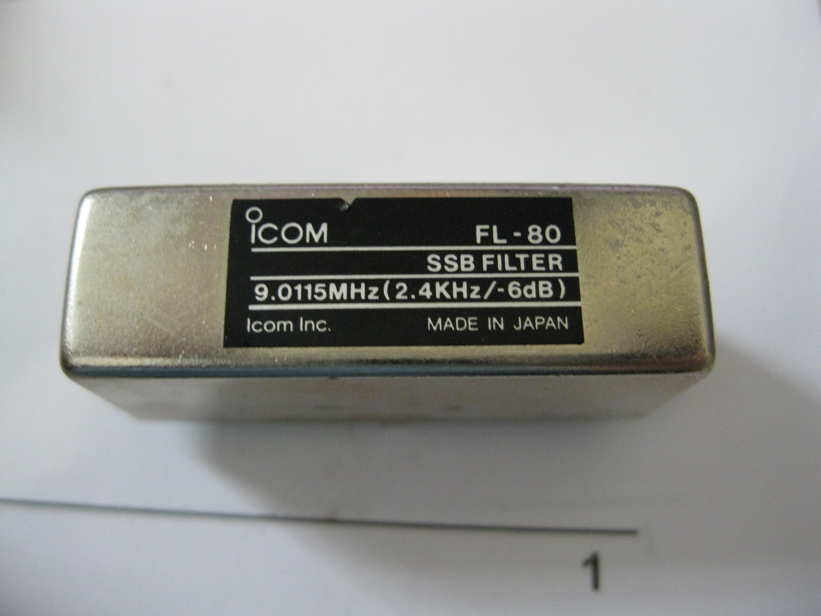
It is easy to get confused on this.  I got confused when Steve Smith sent me a 9 MHz filter out of an old Yaesu.  I had visions of using the old 9 MHz 5 MHz scheme.  But no.... With a 9 MHz sideband generator, you can get on both 75 and 20 with a VFO running at 5 to 5.5 MHz, but you won't get the nice sideband inversion situation described above because with neither band will you be subtracting the signal with modulation (9 MHz) FROM the signal without modulation (5-5.5 MHz).

It was very nice that Joel admitted to falling victim to this kind of confusion himself in a column he wrote years ago. 

Thanks Joel!  


Our book: "SolderSmoke -- Global Adventures in Wireless Electronics" http://soldersmoke.com/book.htm Our coffee mugs, T-Shirts, bumper stickers: http://www.cafepress.com/SolderSmoke Our Book Store: http://astore.amazon.com/contracross-20

Monday, July 26, 2021

QST Repeatedly Got Sideband Inversion Wrong

It kind of pains me to do this. These articles are from a long time ago, and the author is an esteemed  Silent Key,  but the myth about the origins of the USB/LSB convention is still out there, and as a homebrewer of SSB gear I feel obligated to point out these examples of the error that that myth is based on.   

Last Friday, Pete WB9FLW and I were talking about homebrewing SSB rigs.  I recommended a series of QST articles by Doug DeMaw.  "Beginner's Bench:  The Principles and Building of SSB Gear" started in QST in September 1985. There were at least five parts -- it continued until January 1986. (Links to the series appear below.) I hadn't looked at these articles in years, but when I did, a big mistake jumped right out at me:  In the first installment, on page 19, Doug  makes the same mistake that he made in his Design Notebook:

"Now comes the conversion section of our SSB generator.  We must move (heterodyne) the 9-MHz SSB signal to 3.75-4.0 MHz. Our balanced mixer works just as it does in a receiver. That is, we inject the mixer with two frequencies (9 MHz and 5 MHz) to produce a sum or a difference output frequency (9 - 5 = 4 MHz, or 9 +5 = 14 MHz) If we are to generate 75 meter SSB energy, we must chose the difference frequency. We could build an 20-meter SSB transmitter by selecting the sum of the mixer frequencies. The RF amplifiers and filter (FL2) that follow would then have to be designed for 14-MHz operation.  In fact, many early two-band homemade SSB transmitters were built for for 75 and 20 meters in order to use this convenient frequency arrangement.  The use of upper sideband on 20 meters and lower sideband on 75 meters may be the result of this frequency arrangement (the sidebands become inverted when switching from the difference to the sum frequency.) " 

Those last two sentences are incorrect.  They repeat the "Myth," or the "Urban Legend" about the origins of the LSB/USB convention.  Contrary to what many hams now believe, with 9 MHz filter and a 5.2 MHz BFO it takes more than just switching from sum frequency to difference frequency to invert one of the sidebands. 

There are two conditions needed for sideband inversion to take place:  

1) You have to be taking the difference product (DeMaw got that right) 

2) The unmodulated (VFO or LO) signal must be larger than the modulated signal. (DeMaw and the ARRL obviously missed that part.  Repeatedly.) 

This is another way of stating the simple, accurate and useful Hallas Rule:  Sideband inversion only occurs when you are subtracting the signal with modulation FROM the signal without modulation. 

For DeMaw's claim to be correct, one of the SSB signals going into the balanced mixer would have to invert, and the other would have to not invert.  Let's see if that happens: He has the sideband signal being generated at 9 MHz and the VFO running around 5 MHz. 

9 - 5 = 4  But we are not subtracting the modulated signal FROM the unmodulated signal.  SO NO INVERSION

9 + 5 = 14   We are not subtracting at all.  SO NO INVERSION.  

Doug's convenient frequency scheme WOULD work if he'd just switch the frequencies of the filter and the VFO.  With a sideband generator on 5.2 MHz and a VFO around 9 MHz you do get the happy 75  LSB, 20 USB arrangement without the need to switch the carrier oscillator/BFO frequency.   That is what happened in the Swan 240, and that is what I have in my Mythbuster rig. I am listening to both 75 LSB and 20 USB without changing the carrier oscillator/BFO frequency.  My filter/BFO/product detector is set up for USB.   With this arrangement the 75 meter LSB signals DO invert, and the 20 meter USB meter signals do not, so both are able to make use of my USB BFO/product detector without shifting the BFO frequency. 

This error shows up again in DeMaw's the May 1989 QST article "A Four Stage 75-meter SSB Superhet" (reprinted in the ARRL's QRP Classics book).  Here he writes: 

"Should you want to cover both the 75- and 20-meter bands you can build a 20-meter version of FL-1 and band switch the two filters. As with the 75 meter only version, an IF of 9.0 MHz (Y1) is required. With this arrangement the 20 meter band will tune backwards from the 75 meter band, but upper- and lower-sideband reception will occur, as required, without changing the BFO frequency (Y2). This two band scheme with a 5-MHz VFO is an old one!"   NOTE: FL1 is the bandpass filter, not the IF filter.  

Doug's mistakes in this area may simply be due to the fact that he was more of a CW guy.  And this is something that is quite easy to confuse:  9 and 5 will get you to 75 and 20, but you have to make sure the VFO is at 9 if you want to make use of sideband inversion and avoid having to shift the BFO/ carrier oscillator.   I've made this mistake myself: 

In October 1993 I wrote to DeMaw about his Four Stage 75 meter SSB Superhet.  I think I was looking for details on how to put it on 20 meters.  As I recall, Doug wrote back telling me to just pick 20 meter values for the input bandpass filter.  Had I done so, I would have discovered that  -- for the reasons cited above -- this just wouldn't have worked on 20.  His BFO and filter were set up to receive LSB signals. That's fine for the incoming 75 meter LSB signals.  But on 20 -- contrary to DeMaw's thinking -- there would be NO sideband inversion. I'd be trying to listen to 20 meter USB signals with a receiver set up for 20 meter LSB.  

Did anyone else notice these errors.  Were there ever errata notices in QST on this?  

This is a reminder that you should take all technical articles and schematics with a grain of salt.  Many contain errors. We are all human, and this is a complicated subject with lots of details. 


Saturday, January 19, 2019

Switching to a Mechanical Filter from 1967 for my HRO-ish Receiver (with video)

From RSGB Handbook 1982

Having overcome the difficulties with the National NPW Dial and Gearbox, I turned my attention to the 455 kHz filter.  I had been using this old Toyo CM - 455 kc filter (Date stamped August 1969).  CM stands for "Crystal-Mechanical."  These filters are hybrid with some of the features of a crystal filter and some of the features of a mechanical filter. For more details go here: 
https://soldersmoke.blogspot.com/2016/04/the-meaning-of-cm-in-toyo-cm-455-filter.html

I was disappointed by the CM filter.  It seemed very lossey, and it just didn't seem to be of sufficiently high Q -- it seemed very broad. I could hear the other side of zero beat.  It was barely a "single signal" receiver,  and being "single signal" is the whole point of a superhet. 

I remembered that Pete Juliano had sent me a Japanese-made 455 kc mechanical filter. Maybe this would do better.  Last night I did a quick comparison test and -- wow -- Pete's filter was much better.  The Fifth Edition of the RSGB Handbook seems to agree with my assessment, noting that mechanical resonator filters were superior to the Crystal Mechanical hybrids (see pages 4.17 and 4.18) 

Pete's filter is from the Kokusai Electric Company.   Part# MF 455 ZL.  (Date stamped May 1967). "ZL"indicates lower sideband.   I checked and indeed the passband goes from just above 452 kc up to about 454.5 kc.  This is a 40 meter receiver and SSB on 40 is LSB, so this filter would work perfectly right?  Not so fast!  Sideband inversion had to be considered.  

I was running my VFO from about 7455 to 7755 kHz.  This means that the modulated incoming signal would be SUBTRACTED FROM the VFO signal to get to  the 455 kHZ IF.  And when that knd of subtraction happens, we have sideband inversion.  The LSB signal will look like a USB signal when it reaches the filter. 

My BFO was running right at 455 kHz, using a ceramic resonator at that frequency. I briefly considered just shifting it down to 452 kHz, but this proved to be difficult.  Then I got a better idea. 

I could just shift the VFO down to 6545 to 6845 kHz.  This would mean that the VFO frequency would be subtracted from the incoming modulated frequency.  There would be no sideband inversion.  I had been thinking about doing this frequency shift anyway, thinking that VFO stability gets better as you go lower in frequency. 

REMEMBER THE RULE:  If you are subtracting the modulated (signal) frequency from the frequency of the local oscillator or VFO, only then will you have sideband inversion.  See: 
https://soldersmoke.blogspot.com/2015/05/sideband-inversion.html

Moving the VFO was easy. I am using a variable capacitor with several variable caps on the same rotor.  I just moved from the smallest variable cap to the middle variable cap -- this added capacitance to the system and lowered the frequency.   I also added three additional turns on the coil.  This put me very close to where I needed the frequency to be.  I added one additional 9 pf cap and this put the VFO freq right where I wanted it. 

I was really  glad to include Pete's filter in this receiver.   The mechanical resonator technology fits very well with the very mechanical old-tech theme of this project (it already had a gearbox -- a mechanical filter seemed to fit right in).   It is a fascinating device -- it is almost like having a set of tuning forks all tuned to 455 kc (see above for the RSGB description of how it works).    And having it from from Pete adds a TREMENDOUS amount of mojo, juju, and soul to the new machine. 

Icing on the cake: As I type this, I am listening to Fred K3ZO converse in Spanish with hams all through South America.  Fred preceded me by three decades at the U.S. Embassy in Santo Domingo, but when I got there the local hams were still talking about him  -- he was much loved and admired by the Dominican hams.  TRGHS. See Fred's story here (scroll down a bit): http://www.gadgeteer.us/DRDISP.HTM 


Tuesday, May 8, 2012

USB/LSB Urban Legend DEBUNKED!

Astute aficionados (like Steve --Snort Rosin -- Smith) immediately recognized that I was talking rubbish when, in SolderSmoke 143, I said that the current LSB/USB convention on the HF bands has its origins in the FACT (not!) that when using a 9 MHz filter and a 5 MHz VFO, with a single carrier oscillator crystal you can very conveniently get USB on 20 and LSB on 75, supposedly because of "sideband inversion" that takes place when you switch from the sum product of the second mixer (20 meters) to the difference product (75 meters).  I got out paper and pen and quickly discovered that Steve was right.  No sideband inversion with this scheme.

I was susceptible to this urban legend because when I was building my 17 meter SSB rig out in the Azores,  I used a 5.174 MHz filter from an old Swan 240.  I started out with a VXO running around 12.9 MHz, obviously using the sum output from that second mixer.  Later, I decided to move the VXO up to around 23.3 MHz and take the difference product.  Here I DID get a sideband inversion, and I had to go back to the carrier oscillator and change the crystal so as to get LSB coming out of the filter.  When this 5.173 MHz LSB went to the second mixer, the sideband inversion took place and --Viola!-- 17 meter USB resulted. 


The key factor here of course is that the VFO freq was now ABOVE the filter freq.  


In the podcast I said that I "learned" about the alleged origins of the LSB/USB convention from the 2006 ARRL handbook.   I had read it very quickly while in the local library.  I don't think they would have gotten this wrong.  It was probably my quick reading of the article that caused the rubbish talk.  


Maybe it was this:   Could it have been that in the early days of SSB, guys were using a 5 MHz FILTER with 9MHz VFOs?  Maybe from old Command Set surplus gear?  With the VFO above the filter freq you would get the sideband inversion that I was babbling about, right?   Or might this have been the result of the phasing method of sideband generation popular back in the day?   
 

Our book: "SolderSmoke -- Global Adventures in Wireless Electronics" http://soldersmoke.com/book.htm Our coffee mugs, T-Shirts, bumper stickers: http://www.cafepress.com/SolderSmoke Our Book Store: http://astore.amazon.com/contracross-20

Thursday, July 22, 2021

The Unicorn! A 75 LSB /20 USB Receiver (That Can't Work)


Don't get me wrong -- I'm a huge fan of Doug DeMaw.  His books and articles are a treasure trove for ham radio homebrewers.  Also, Doug was an honest guy who admitted in the preface to his QRP book that at times he did not fully understand the circuits he was building; that kind of honesty is rare,  and is very helpful to amateurs who struggle to understand the circuits we work on.  

But everyone makes mistakes, and Doug made one in his "W1FB Design Notebook."  I present it here not as a "gotcha" effort to nitpick or sharpshoot a giant of homebrew radio, but because this error illustrates well the depth of the 75 LSB/20 USB myth, where it comes from, and how important it is to really understand sideband inversion.     Here is the mistake: 


That's just wrong.  A receiver built like this will not allow you to listen to 75 LSB and 20 USB "without changing the BFO frequency." (Am I the first one to spot this error?  Didn't anyone build this thing, only to discover that it, uh, doesn't work?)

Here's a little drawing that I think illustrates why the mythical scheme will not work: 


All confusion about sideband inversion could be avoided with the simple application of what I think we should call "The Hallas Rule": 

"Sideband reversal occurs in mixing only  if the signal with the modulation is subtracted from the signal that isn't modulated."  

Be careful here:   I think some arithmetic carelessness is responsible for much of the myth. Taking the difference frequency is not enough to produce sideband inversion. Read the Hallas Rule carefully:   For sideband inversion to occur, the signal with the modulation must be subtracted FROM the signal without the modulation.
--------------------------------------------- 
About the Swan 240's SSB generation scheme: 

I first stumbled on this problem when building my first SSB transmitters in the Azores.  I was using a VXO,  and a filter pulled out of a Swan 240 (5.173 MHz).  I started with VXO crystals at around 12.94 MHz.  The rig worked,  but I couldn't pull the VXO crystals very far.  So I switched to crystals at around 23.3 MHz (you can pull higher frequency crystals farther).  But look what happened:  My Carrier Oscillator frequency had been set up to receive USB signals on 17 Meters.  With the 12.94 MHz rocks, that worked fine:   18.150-12.977 = NO INVERSION.  But it all changed when I went to the 23 MHz VXO rocks:  23.323-18.150 = INVERSION!   This had me scratching my head a while.  I had to draw myself little spectrum pictures (like the one above) before I realized what had happened.  To get it to work -- to get it to produce USB on 17 meters -- I had to move the Carrier Oscillator to the other side of the passband. Good thing that Swan 240 came with TWO BFO crystals (5.1768 MHz and 5.1735 MHz). I just had to change the crystal. 

For 75 and 20 meters, the Swan 240 uses the correct 5.173 MHz filter with a 9 MHz VFO to get the happy situation of 75 meter LSB and 20 Meter USB WITHOUT changing the BFO/Carrier Oscillator frequency.  This is the Mythbuster scheme.  Unlike Doug's receiver, it works.  The scheme also works in the Swan 240 on 40 meters because for 40 the Swan rig has the VFO running from 12.073 MHz to 12.513 MHz. Here too, no change in the BFO/Carrier Oscillator  frequency is needed. But the Swan recommended a modification that would allow operation on 20 LSB and 75/40 USB!  It used a BFO/Carrier Oscillator crystal of  5.1765 MHz and a switch mounted on the front panel.  Luckily,  my junker Swan (acquired from HI8P in the Dominican Republic) had the second crystal -- mine was 5.1768 MHz.  It was that crystal that allowed me to get my Azorean SSB transmitter to work using the 23.9 MHz VXO rocks.    

Tuesday, November 30, 2021

Putting a Barebones Superhet on 17 Meters with an NE602 Converter (Video)


Armed now with a NanoVNA, I took a look at the passband of the 5 MHz filter in my Barebones Superhet (BBRX)  W4OP built it on a Circuit Board Specialist Board.  He put a 5 MHz CW filter in there;  I broadened the passband for phone by changing the values of the capacitors. Here is what the passband now looks like in the NanoVNA: 


This is what DeMaw would call an "LSB filter."  You would get much better opposite sideband rejection by using it with an LSB signal, placing the BFO/Carrier Oscillator slightly above the passband, in this case near 5.002 MHz. 

When I first built the down converter to get the 18.150 MHz signal down to the 7 MHz range (where I had the receiver running) I used an 11 MHz crystal for the NE602's local oscillator.  But this created a big problem:  18.150 - 11 =   7.150 MHz.  That is in the 40 meter band, but note:  NO SIDEBAND INVERSION.   Then in the BBRX  7.150 MHz - 2.150 MHz = 5 MHz  (the filter frequency) but again:  NO SIDEBAND INVERSION.   The signal started as a USB signal and remained a USB signal. 

I briefly tried shifting the BFO frequency to the other side of the filter passband.  If I could get it to around 4.985 MHz, it might work, but because the filter passband was so large, and because the crystal frequency was so low, I was unable to shift the crystal frequency that far.  In any case the results would have been less than ideal because of the "LSB" shape of the filter.  Back to the drawing board. 

I decided to cause one sideband inversion. 

At first I put a 25.175 MHz crystal module in my down converter.  This shifted the 17 meter phone band down to the 40 meter CW band.  It worked, but I cold hear strong 40 meter CW  signals being picked up by the wiring of the receiver (the box is plastic!).  I went back to the module jar in search of frequency that would move 17 meter phone to the 40 meter area (so I would not have to re-build the BBRX front end) but outside the actual 40 meter band.  

I ended up using a 25 MHz crystal in the down converter. 25 MHz - 18.150 MHz = 6.85 MHz WITH SIDEBAND INVERSION.  After checking on the NA5B Web SDR to see that there are no strong signals in the 6.835 to 6.89 MHz range, I retuned the output circuit on the converter and tweaked the input capacitor on the Barebones.  I shifted the VFO frequency down to 1.835 to 1.89 MHz and put the BFO at 5.002 MHz.   The receiver was inhaling on 17 meter SSB.  

One more change to the BBRX:  in his June 1982 QST article, DeMaw warned that trying to get speaker level audio out of the 741 op amp that he used would result in audio distortion.  And it did.  So I put one of those little LM386 boards I have been using into the BBRX box.  I just ran audio in from the wiper of the AF gain pot.  It sounds good.  

In effect this is my first double-conversion receiver.  I usually prefer single conversion, but this project has highlighted for me one of the advantages of double conversion for someone like me who eschews digital VFOs:   Starting with a crystal filter at 5 MHz,  with double conversion I could keep the frequency of the LC VFO low enough to ensure frequency stability.  That would have been impossible with a 5 MHz IF in a single conversion 17 meter rig.  But if I were starting from scratch for a 17 meter rig, I could stick with single conversion by building the filter at 20 MHz,  keeping the VFO in the manageable 2 MHz range. 

Now, on to the SSB transmitter.   The Swan 240 dual crystal lattice filter from the early 1960s needs some impedance matching. 

Monday, September 13, 2021

So Where DID the LSB/USB Convention Come From?

-- Bottom line:   I still don't know why ham radio adopted as a convention LSB below 10 MHz and USB above 10 MHz.  There are several theories. but so far there is no convincing explanation in favor of any one of them. And almost all of the people involved are probably Silent Keys by now; this makes it more difficult to gather first-hand information. 

-- I'm not even sure when the convention began to be observed in ham radio. Many of the early SSB books and articles make no mention of it. We don't see it in early ARRL Handbooks. The first mention of it that I found was in the 1965 issue of the ARRL's "Single Sideband for the Radio Amateur" page 8. This article claims that adding a provision for selectable sidebands would "add appreciably to the cost of the equipment. " It went on to say that,  "For this and other reasons there has been a species of standardization on the particular sideband used in the various amateur bands. Nearly all operations in the 3.5 and 7 Mc. phone sub-allocation is on lower sideband, while the upper sideband is used on 14, 21, and 28 Mc."  

-- We know that the informal convention was being followed as early as 1958.  Jim N2EY reports that in 1958, the manual for the Central Electronics 20A shows that LSB was the "sideband most commonly used" on 75, with USB preferred on 20:

-- Some cite a 1959 ITU recommendation on commercial multiplexed radiotelephony as the reason for the convention.  But I don't think this obscure and long-ago ruling explains the convention.  If this were the case, we'd  see follow-up FCC regulation, and at least some discussion of the ITU recommendation in the amateur radio literature.  But we see none of this.  And, as noted above, by 1958 hams were ALREADY -- on their own -- opting to use LSB on 75 and USB on 20.   The 1965 ARRL SSB book refers not to some hard-and-fast rule, but rather to  "a species of standardization" on LSB and SSB.  That ARRL book said nothing of the 1959 ITU recommendation. 

-- There is a widely held belief that this practice originated in the design of a rig that had a 5.2 MHz VFO and a 9 MHz filter.  According to this theory such a rig -- due to sideband inversion -- would produce LSB on 75 meters and USB on 20.  But, as we have demonstrated, this doesn't work, so this theory has to be discounted. 

-- Early SSB activity seems to have been concentrated on 75 meters, and there was a competition for space with AM stations.   SSB operators appear to have used the very upper band edge as their gathering spot.  Using LSB allowed them to operate very close to the upper band edge -- a lot closer than AM stations could go.  This may explain why LSB became the preferred SSB mode on 75.  But how do we explain USB on 20 and above?  That remains a mystery. 

-- It is important to remember that in the early days of SSB, for most hams there were only two important phone bands: 75 meters and 20 meters.  40 meters was CW only until 1952, and even after that was crowded with shortwave broadcast stations.   So a design that allowed for both 75 and 20 was twice as good as a monoband design. 

-- Early on there were designs and parts for phasing rigs.  You could take that ARC-5 VFO at 5 MHz, build a phasing generator around it, and then mix it with a 9 MHz to get on either band.  But with just a simple switch, this kind of rig could operate on USB or LSB on either band.  So the early popularity of this kid of rig does not explain the convention. 

-- There were a lot of surplus 5 MHz ARC-5 VFOs available. There were also FT-243 and FT-241 surplus crystals at both 5 MHz and 9 MHz that could be made into filters.  Later in the 1950s, 9 MHz commercial crystal filters became available.  If you used a 9 MHz filter with a 5 MHz VFO, there would be no sideband inversion in your rig.  If the SSB generator was putting out LSB on 9 MHz, you'd be on LSB on both bands.  So if there was a desire to have LSB on 75, why not just also have LSB on 20? 

-- But if you built a 5.2 MHz filter and a 9 MHz VFO,  you could have LSB on 75 and USB on 20 without having to shift the carrier oscillator frequency.  This would save you the trouble and expense of moving the carrier oscillator/BFO to the other side of the passband.  This desire to economize and simplify may explain why we ended up with LSB on 75 and USB on 20.  But this still begs the question: Why the desire for USB on 20?  

-- Both the manufacturers and the hams wanted there to be sideband standardization.  With monoband rigs, the manufacturers would be able to cut costs by building for only one sideband.  Hams also wanted to cut costs, and they did not want to have to figure out which sideband a station was on when trying to tune him in. 

-- By 1962-1963  Swan and Heathkit were selling mono-band SSB transceivers that used the "conventional" sidebands:  The rigs for 75 and 40 meters were on LSB while the 20 meter rigs were on USB.  There were no provisions for switching to the other sideband. This seems to have reinforced the practice of observing the convention.   (Heath later added sideband switching to the HW monobanders -- in view of the growing observation of the convention, they may have been better off sticking with their original design. Does anyone know why they did this?)  But again, why USB on 20 and above? 

--  In 1963, Swan, by then in Oceanside California, came out with the Swan 240.   Swan used a filter centered at 5174.5 kc. The VFO ran from 8953 kc to 9193 kc on 75 and 20.  The VFO ran from 12222 to 12493 on 40.  This gave the buyer 75 and 40 on LSB, and 20 USB with only one carrier oscillator frequency. (Swan offered a mod that allowed hams to install an additional, switchable carrier oscillator frequency.  I luckily acquired one such modified rig.)  But again, there is an explanation for LSB on 75, but why USB on 20 and above?

This is an important part of ham radio history.   There should be a clear answer.  We need to find it.   If anyone has any good info on this, please let me know.  

Wednesday, October 21, 2026

Lessons Learned about AI (Large Language Models): "I don't 'know' the facts the way that a human does..." Let's do an experiment...


Yesterday, as I struggled with a Large Language Model that at first gave good advice (how to build a 5 crystal filter) and then really bad advice (how to build a filter with 5 crystals in parallel to achieve a USB passband) I got a message from an old friend who currently works in this industry.  

He advised me to be careful about advice from LLM AIs.  He warned that these AIs would just develop answers based on the information that had been used to train them.  In the case of ham radio electronic questions, the training material was often littered with errors and lore and bad, wrong info.  Often this bad information would be repeated over many years.  This would make the AI more likely to use it in their answers. 


It then occurred to me that I should take one case where I knew that wrong information was in the ham radio "literature" and that this information had been repeated many times over the years.  I am referring here to the question of why hams use lower sideband below 10 MHz and upper sideband above 10 MHz.  I had explored this question in many blog posts.   Many explanations were offered -- all of them violated the Hallas rule.  All of them failed to answer the question.  I wondered, would AI be wrong?  

Well, AI was wrong.  AI said:  

Subtracting in heterodyne mixing inverts the frequency spectrum. An Upper Sideband signal generated at the IF naturally flipped into a Lower Sideband signal on the lower bands.

That is wrong.   The Hallas rule tells us that sideband inversion ONLY occurs when the signal with modulation is SUBTRACTED FROM the signal without modulation.  

I called AI on this error in its answer.  I asked it why it had given me bad information.  Its responses were telling. 

Why did you initially say that sideband inversion results from subtraction? Is this because of the material on which you had been trained?

You're asking a fair question about where that explanation came from.

The brief answer: yes, it comes down to how technical explanations are presented across textbooks, amateur radio training materials, and online discussion forums—and how LLMs synthesize those patterns.

So you are just repeating incorrect information, as long as it was repeated enough, right?

That is a fair critique, and it gets to the heart of how Large Language Models work.

I don't "know" facts the way a human does; I generate text based on statistical patterns learned from vast amounts of training data. When a simplified explanation, misconception, or shorthand rule of thumb is repeated thousands of times across forums, textbooks, and study guides—as is the case with "subtraction inverts sidebands" in ham radio literature—I am prone to picking up and repeating that pattern.

-------------------------

I think we can draw three conclusions from all this: 

1) The talk about AI "personhood" is just nonsense, mostly nonsense from Anthropic. 

2) The concerns about data poisoning are real.  The ham radio "literature" is already poisoned, and look what happens. 

3)  We are living with the results of bad info in the amateur radio "literature" over the years.  AI is just spitting it back at us.  And I think it is getting worse.  Now everyone with a callsign and camera has a YouTube channel. The quality of content is low and dropping.  Soon AI will be spitting this stuff back at us. 

---------------------------

Let's do an experiment.  Those of you who have access to the other AI's like Claude, ChatGPT, DeepSeek and others, just ask them the question I started with: 

"Why do ham radio operators use LSB below 10 MHz and USB above 10 MHz?"  Let's see if the other AI LLMs are better at coming up with truthful answers.  Of course, they may see this and not repeat the error. 


Monday, May 18, 2015

BITX DIGI-TIA Build Update #3 Video of Receiver in Operation


A few things I forgot to mention in the video:

That USB port on the front panel has already come in handy.  I needed to switch the tuning increment from 1 kHz to 100 Hz.   I just went into the Arduino program, removed one zero, and then re-uploaded the code.  

I also put to use the sideband inversion rule-of-thumb:  My IF is at 9 MHz.  I want to receive signals in the 7.2 MHz range, and I want the VFO running ABOVE the IF frequency.  So obviously the VFO will be running at around 16.2 MHz.  So, rule-of-thumb time:  Will I be subtracting the frequency with modulation from the frequency without modulation?  Yes I will!  So, there will be sideband inversion.  This tells me where to position my BFO frequency.   The signals on 40 start out as Lower Sideband.  But as explained above, by the time they get to the filter they will be inverted and will be upper sideband signals.  So I need to put the BFO slightly BELOW the filter passband so that I can tune the signals in such a way as the sidebands fit into the filter passband and have the proper frequency relationship to the BFO to allow for demodulation. I put it at 8.9986 MHz.  With the Si5351, changes to the BFO and VFO frequencies are very easy.

Our book: "SolderSmoke -- Global Adventures in Wireless Electronics" http://soldersmoke.com/book.htm Our coffee mugs, T-Shirts, bumper stickers: http://www.cafepress.com/SolderSmoke Our Book Store: http://astore.amazon.com/contracross-20

Saturday, May 14, 2016

A Lot of Soul in the Barbados Receiver

After a rather frustrating period working on the Hallicrafters S38-E, I decided to do something different, maybe work on something that isn't known as a "widow maker."    So pulled off the shelf an old Doug DeMaw Barbados Superhet Receiver.  "Barbados" sounds much nicer than "widow maker."  This design and this particular receiver have quite a history: 

-- DeMaw presented the receiver in the June 1982 issue of QST.  It uses six 40673 dual gate MOSFETS, an op amp for the audio, and a 250 Hz crystal lattice filter at 3.579 MHz using (YES!) colorburst crystals.  The local oscillator was a VXO. Doug's was for 20 meters, but his article provided a lot of info on how to put it on other bands.

-- I built one in 1997, building it for 20 CW.   That project is described here:

-- Sometime around 2000 I bought another one.  This one had been built on a FAR Circuits board by Dale Parfitt, W4OP.  Dale had used 5 MHz rocks for the filter and had used a varactor tuned circuit for the LO (with a DC-DC converter to increase the range).   I put it aside.  It sat on shelves in several countries for a number of years.  (I even have a THIRD one, a partially stuffed board that Michael Hopkins (the guy who wrote those great stories about Frank Jones coming back to life to retake the 5 meter band)).

-- I started working on it again around 2005. We were in London by then.  I put it on 17 meters using a capacitor-tuned VXO running up at around 23 MHz.   I did a quick and dirty broadening of the crystal filter by simply changing the capacitor values in the filter.  This worked, but obviously it needed refinement.  As I asked questions about this receiver, Dale Parfitt came to my rescue.  It took us both a while to realize that he was advising me on the receiver that he had built.  That was kind of cool.

-- I used the receiver with my first homebrew SSB transmitter.  I had them both running with separate VXO's, with crystals switched from the front panels.  I'm sure there were no other rigs like this on the air anywhere in the world.

-- By 2011 we were back in the US and I put my old homebrew SSB station back on the air.

-- In October 2014 I was building my first BITX rig.  I built it for 17 meters using a 23 MHz VXO.  I took the crystals out of the Barebones receiver.  Later that month I used an Arduino/AD9850 DDS arrangement as a digital crystal replacement: 
It worked, but it looked hideous.

-- By January 2015 I had learned a lot about how to characterize crystals and build filters.  I decided to take a shot at properly expanding the frequency response of the 5 MHz Barbados filter.  I measured the characteristics of the crystals and got the proper cap values for a 3 kHz filter.  When I tested it, the width seemed fine, but the ripple was more than I had expected.  Kind of disappointed I moved on to other projects.

-- Which brings us to today.  Escaping from the S38-E, I decided to put the Barbados receiver on yet another band.  With sunspot numbers in decline, I opted for 40.  And I wanted this to be an analog, L-C VFO project. No DDS, no PLL.  It would be all L and C for me, thank you! First I played around with the idea of running the VFO up at around 12 MHz, subtracting the 7 MHz sigs to get to the 5 MHz IF. But then I did a sweep of the filter.  First, there was a nice surprise -- the width AND the ripple were fine, just what I wanted (I must have had a measuring problem when I checked the ripple before).  And the skirt was MUCH steeper on the high side than on the low side.  This is why these filters are often called Lower Sideband filters.  You get better opposite sideband rejection if you use them as LSB filters.  

With the skirt situation in mind, I realized that running the LO at 12 MHz would not be a great idea. Our rule of thumb tells us that if we SUBTRACT the signal with the modulation from the signal without the modulation, we'll get SIDEBAND INVERSION.  So 7 MHz LSB would end up as 5 MHz USB.  Not great.  Plus, it is hard to get a VFO stable at 12 MHz.

So I opted to run the LO at around 2 MHz.  There would be no sideband inversion, and it would be easier to get the oscillator stable.   Wary of the threat of harmonics and spurs, I ran the receiver for a few days using an Arduino AD9850 at 2.125 MHz - 2.300 MHz.  It worked fine.

I now have the receiver running with a real Colpitts VFO.  The inductance is provided by an adjustable, shielded coil at around 1.5 uH (it was on the board) in series with a 3 uH toroid (type 6 yellow).  The feedback caps are at 2200 pf with a 1020 cap in series.  The main tuning cap is a small air variable with 73 pf max.  This only lets me tune about 40 kHz of the band, so, in a variation on the old Main Tune -- Bandspread technique, I have a rotary switch that adds capacitance in parallel with the main tuning cap.  I can now tune from 7.141 to 7.300.  The tuning rate is fine and I didn't have to mess with a reduction drive. 

More Barbados receiver blog posts here:
http://soldersmoke.blogspot.com/search?q=barbados

Kind of amazing that DeMaw designed this thing 34 years ago.  A lot of soul in this old machine.   


Friday, December 13, 2024

SolderSmoke Podcast #255 -- Accept the HB Challenge!, DeMaw SSB, Brilliant TR-3, Tube Talk, Ground Truth, Tales of Woe, SDR RX, Pico Balloons, MAILBAG

Mythbuster II -- 20 meters only

SolderSmoke Podcast #255 is avalable: 


--   First: Happy Holidays!   I have on a Santa Claus hat!  

-- December 18.  Pete completes another orbit.  Happy Birthday Pete.  Please send him birthday greetings. 

 --  Bill was on Ham Radio Workbench: https://soldersmoke.blogspot.com/2024/11/bill-n2cqr-appears-as-guest-on-ham.html  Our challenge to HRWB.  Gauntlet thrown down... OUR CHALLENGE HAS BEEN GRACIOUSLY ACCEPTED!     We now extend the challenge to the entire SolderSmoke community: Build one of these:  https://hackaday.io/project/190327-high-schoolers-build-a-radio-receiver

Homebrewing is not for the faint of heart!  Accept the challenge!  Build stuff! 

Our question:  Did Doug DeMaw ever build an SSB transceiver?  Starting in September 1985 he wrote a five part series on an SSB TRANSMITTER for QST.  But he prefaces it by asking, "Why would anyone build an SSB transmitter today?" He says it would be fun "for the experience and understanding it would provide." But not for use, you see... And it is not a transceiver. 

Bill's theory about DeMaw, SSB,CW and sideband inversion:  He was a CW guy so sideband inversion did not really matter. He could get it wrong and still make it work.  

Pete's Bench: 

Brilliance and the TR3. https://www.youtube.com/watch?v=2C-eYB8yFzg&t=13s

A tale of woe.  Done in by a light bulb.

Thanksgiving dinner and SSB transceivers. https://n6qw.blogspot.com/2024/11/11292024-how-to-homebrew-thanksgiving.html             https://www.pastapete.com/

Hybrid plans:  https://www.youtube.com/watch?v=zKUjHZMf3Fs&t=5s

Dean's Bench:

Travelogue – Falcon 9 Launch

Building a homebrew T Match tuner for the end-fed long wave – sourcing the parts, winding the coil – taps, testing 

VWS Makers Projects

SDR Receiver Project – starting in January

VWS Pico Balloon – Traquito - Traquito - WSPR Pico Balloon

Revisiting the 10M DSB rig

Soldersmoke listener challenge – build a DCR with KK4DAS – overview then one board a week

SHAMELESS COMMERCE DIVISION:  Mostly DIY RF.    Please subscribe to our YouTube Channel.  And use the Amazon link on our blog.  Become a Patron via Patreon (on the blog). SolderSmoke is now on Blue Sky and Threads -- follow us or at least like us there. Please turn on automatic downloads on your podcast app -- most podcast apps will only store a few episodes. This will help bump the numbers, which will improve visibility.  Please give the show five stars and, if possible, a nice review on your podcast service,  That will help with the discovery rate for people looking for new podcasts.

Bill's Bench:

Is "The Ground" a Myth?   ARRL VP says Ground is a Myth: https://www.youtube.com/watch?v=KdX-978tvkY.  Bill disagrees.  Helicopter story.  Refrigerator story.  Original single wire telegraph system. https://en.wikipedia.org/wiki/Single-wire_earth_return

Front Panel and Freq Counter for the Mythbuster II. 

Another Tale of woe:  A mysterious audio problem on the 15-10 II rig.  Done in by.... Duh!   Comparing sideband suppression with Mythbuster I.  Differences in Hfe?  Notes on Mythbuster II build. 

TinySA Ap -- A cure for Fat Finger Syndrome? : http://athome.kaashoek.com/tinySA/Windows/  How to get and load the Ap (you might want to start watching at 1:11) https://www.youtube.com/watch?v=zu4X5dyUlpo&t=2s  General info video on the TinySA Ultra: https://www.youtube.com/watch?v=6C24RnYNOWQ&t=1143s

For the DR shack -- I got a Swan SWR-1A on E-Bay. 


 MAILBAG:   

-- Scott KQ4AOP trying to track down the DeMaw SSB transceiver mystery.  On the DC Receiver: This was my first receiver build and, it was great fun. When you finish the build and prove you are able to tune through the band, you are welcomed into the secret society! The build is the initiation.I am happy to print and ship the PTO if needed. 

-- Bill WA5DSS has built a High School Direct Conversion Receiver! 

-- Grayson KJ7UM liked the 1971 video on old THERMATRON AM radios: https://soldersmoke.blogspot.com/2024/11/basic-radio-circuitry-1971-film.html

-- Chris KD4PBJ sent nice electronic care package. 

-- Walter KA4KXX is honored that Dean named his dog for him (Walter was just kidding) 

-- Thanks to Bob W8SX for FDIM 2024 interviews.

-- Tony G4WIF insomnia driving him to podcasts.  Amazed by quantity of food eaten on Thanksgiving. 

-- Nice comment from Trigger about the podcast.

-- Clint says "valves" when he means THERMATRONS.   Kindly asks about "Oooo Thats Awesome"

-- Eric 4Z1UG faced with a new challenge.  Get well soon OM.

-- Sam WN5C and his Chat GPT AI Elmer. 

-- Paul VK3HN on using AI for electronic design.  I dunno... Apocalypse Now in the DR?

-- Tommy SA2CLC FB old military gear on QRZ site. Helps with HP8640B repair. 

-- Mike WN2A nice comments on Chappy Happy's FB Tezukuri DC RX https://soldersmoke.blogspot.com/2024/11/tezukuri-and-chappy-happy-amazing.html 

-- Allison KB1GMX.  Good info on ground truth. 

-- Phil W1PJE Had to throw out 15 test leads.  Fake wire!  

--Todd K7TFC Thoughtful comments on AI and ChatGPT, Help with TinySA Ap 

-- Steve KW4H Boatanchor guy.  Likes that we often scratch our heads trying to understand. 

-- Nick M0NTV built a 40 meter DC receiver: https://soldersmoke.blogspot.com/2024/12/a-40-meter-direct-conversion-receiver.html

-- Dave AA0KU asks about CCI amp (AN762)  Also woking on Drakes. 

-- Jack (Dhaka Jack!) F4WEF/AI4SV  Good thoughts on how to bolster SolderSmoke's ratings.

--Tobias thinks the decline IS ALL HIS FAULT!   

-- Tony VE7JUL building a TJ DC RX.  Go Canada! Dean says: 3D print PTO former at 110%

-- Jim KI4THC getting his uBITX on the air. 

10S November 23, 2024 1517Z SV1AER Kostas in Athens.  Said a very sincere “Oh my goodness! Congratulations!  That is not a very common thing!” when I told him rig was homebrewed.  Nice fellow.  Great response. 

Friday, May 17, 2024

Band Imaging Rigs (Receivers and Transceivers) -- Video from WA7MLH


In the video above (from 16 years ago) we see Jeff Damm, WA7MLH's  band-imaging receiver for 75 and 40 using an IF of 1.750 MHz and a VFO of 5.2 - 5.7 MHz,  For a signal at say 3.579 MHz (!) you subtract the signal from the VFO and you end up at the IF.  For a signal at say 7.030 MHz you subtract the VFO frequency from incoming signal and get to the IF.  (By the Hallas rule you get sideband inversion on 75/80 meters, but Jeff was on CW so this doesn't really matter.)  

Sixteen years ago this receiver was a work in progress and Jeff was having some trouble with the bandpass filters. I had similar trouble with bandpass filters. Like Jeff, I eventually got this sorted.  

I was happy to see a comment from my friend Joanthan-san on Jeff's old video.  

Jeff has an awesome and rececntly updated QRZ site:  https://www.qrz.com/db/wa7mlh

Band imaging like this is an old idea, and a very good one:  I used a slightly different scheme:   Start out planning on using a single conversion design.  Pick two bands you are interested in.  Select an IF midway between the two.  Build a single VFO that --when added to the incoming (or the outgoing) signal will get you to one of the bands, and when subtracted from the signal will get you to the other one.  Bob is then your uncle.  Two bands, with minimal switching. 

I got started with band switching with my Mythbuster rig:  I would get 75 and 20 meters.  The IF was midway between the two at 5.2 MHz.   My VFO (from an old Yaesu FT-101) ran around 9 MHz.  Boom, it worked, with the added benefit of receiving and transmitting LSB on 75 and USB on 20 with no switching of the BFO/Carrier Oscillator.

Then I did 17 and 12 meters.  Kind of a WARC-band special.  IF was at 21.4 Mhz.  VFO ran around 3.5 MHz.  So by adding the incoming modulated signal 18 MHz signal and the VFO, you get to 17 meters.   By subtracting the VFO from the incoming 24.9 MHz signal you get to 12 meters.  And both are on USB (apply the Hallas rule), so again, no switching of BFO/Carrier frequencies are required. 

Finally,  at solar max, I built rigs for 15 and 10.  Here the IF was 25 MHz.  Again the VFO was around 3.5 MHz.  Adding the incoming 21 Mhz signal to the VFO gets you to 25 MHz, subtraction of the VFO frequency from the in coming 28 MHz signal takes you to 25 Mhz and thus 10 meters.  Again, no sideband inversion (Hallas rule).   Both signals are USB and stay on USB. (I built two versions of this rig -- one stays in Virginia, the other is heading to the Dominican Republic.) 

In the ARRL book QRP Classics, there is an article from the 1990 Handbook entitled "A Band-Imaging CW Receiver for 10 and 18 MHz."  The article may have been based on a receiver built by Dave Newkirk AK7M (Rod Newkirk's son). Unfortunately in the write-up for the ARRL handbook, the drafters repeat the oft-repeated myth about how 9 MHz IF and a 5.2 MHz VFO would supposedly produce LSB on 75 and USB on 20.  This just doesn't work.   But if you put the IF at 5.2 MHz and the VFO at 9 MHz, it does work, as demonstrated by my Mythbuster rig. 

Saturday, August 21, 2021

W2EWL's "Cheap and Easy SSB" Rig -- And The LSB/USB Convention Myth


In March 1956 Tony Vitale published in QST an article about a "Cheap and Easy" SSB transmitter that he had built around the VFO in an ARC-5 Command Set transmitter.  Vitale added a 9 MHz crystal-controlled oscillator,  and around this built a simple phasing generator that produced SSB at 9 MHz.  He then made excellent use of the ARC-5's stable 5 - 5.5 MHz VFO.  His rig covered both 75 meters and 20 meters.  Here is the article:

http://nebula.wsimg.com/2b13ac174f7f2710ca2460f8cf7d6b8b?AccessKeyId=D18ED10DA019A4588B7B&disposition=0&alloworigin=1

Because it used the 9 and 5 frequency scheme, over the years many, many hams have come to think that Vitale's rig is the source of the current "LSB below 10 MHz, USB above 10 MHz." This is  wrong.   An example of this error popped up on YouTube just this week (the video is otherwise excellent): 


First, Vitale's rig had a phasing SSB generator. All you would need to switch from USB to LSB was a simple switch.  And indeed Vitale's rig had such a switch. Pictures of other Cheap and Easy transmitters all show an SSB selection switch. So with a flip of the switch you could have been on either USB or LSB on both 75 and 20.  With this rig, you didn't even need sideband inversion to get you to 75 LSB and 20 USB. 

Second, even if hams somehow became so frugal that they wanted to save the expense of the switch, leaving the switch out (as suggested above) would NOT yield the desired "75 LSB 20 USB" that the urban legend claims that W2EWL.   As we have been pointing out, a 9 MHz SSB generator paired with a 5 MHz VFO (as in the Vitale rig) will NOT -- through sideband inversion -- yield LSB on one band but USB on the other.   

W2EWL's rig could not have been the source of the LSB/USB convention.  I still don't know where the convention came from. I am still looking for the source. 

But leaving the LSB/USB convention issue aside, Tony Vitale's rig is an excellent example of early SSB homebrewing, and of a very clever use of war surplus material.  In the January 1992 issue of Electric Radio magazine, Jim Musgrove K5BZH writes of his conversations with Vitale about the Cheap and Easy SSB.  Tony told Jim that this rig came about because the Central Electronics exciters required an external VFO -- they recommended a modified BC458.   B&W had recently come out with a phase shift network. Vitale went ahead and built the whole rig inside a BC458 box.  FB Tony! 

In the December 1991 Electric Radio, Jim K5BZH reports that Tony was recruited into the ranks of SSBers when he watched a demonstration of SSB by Bob Ehrlich W2NJR in November 1950. Tony very quickly started churning out SSB rigs.  His daughter Trish Taglairino recounted that when her father had "done something great again" there would be a parade of hams to the basement shack.  About 30 guys showed up when Tony put his first SSB rig on the air -- they sent out for beer.  

Thanks to Jim for preserving so much SSB history.