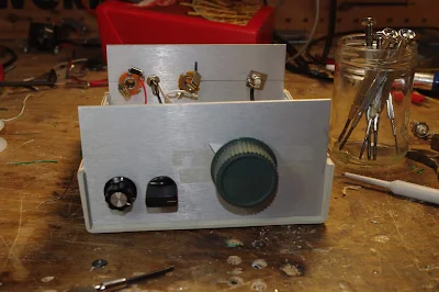
After a rather frustrating period working on the Hallicrafters S38-E, I decided to do something different, maybe work on something that isn't known as a "widow maker." So pulled off the shelf an old Doug DeMaw Barbados Superhet Receiver. "Barbados" sounds much nicer than "widow maker." This design and this particular receiver have quite a history:
-- DeMaw presented the receiver in the June 1982 issue of QST. It uses six 40673 dual gate MOSFETS, an op amp for the audio, and a 250 Hz crystal lattice filter at 3.579 MHz using (YES!) colorburst crystals. The local oscillator was a VXO. Doug's was for 20 meters, but his article provided a lot of info on how to put it on other bands.
-- I built one in 1997, building it for 20 CW. That project is described here:
-- Sometime around 2000 I bought another one. This one had been built on a FAR Circuits board by Dale Parfitt, W4OP. Dale had used 5 MHz rocks for the filter and had used a varactor tuned circuit for the LO (with a DC-DC converter to increase the range). I put it aside. It sat on shelves in several countries for a number of years. (I even have a THIRD one, a partially stuffed board that Michael Hopkins (the guy who wrote those great stories about Frank Jones coming back to life to retake the 5 meter band)).
-- I started working on it again around 2005. We were in London by then. I put it on 17 meters using a capacitor-tuned VXO running up at around 23 MHz. I did a quick and dirty broadening of the crystal filter by simply changing the capacitor values in the filter. This worked, but obviously it needed refinement. As I asked questions about this receiver, Dale Parfitt came to my rescue. It took us both a while to realize that he was advising me on the receiver that he had built. That was kind of cool.
-- I used the receiver with my first homebrew SSB transmitter. I had them both running with separate VXO's, with crystals switched from the front panels. I'm sure there were no other rigs like this on the air anywhere in the world.
-- By 2011 we were back in the US and I put my old homebrew SSB station back on the air.
-- In October 2014 I was building my first BITX rig. I built it for 17 meters using a 23 MHz VXO. I took the crystals out of the Barebones receiver. Later that month I used an Arduino/AD9850 DDS arrangement as a digital crystal replacement:
It worked, but it looked hideous.
-- By January 2015 I had learned a lot about how to characterize crystals and build filters. I decided to take a shot at properly expanding the frequency response of the 5 MHz Barbados filter. I measured the characteristics of the crystals and got the proper cap values for a 3 kHz filter. When I tested it, the width seemed fine, but the ripple was more than I had expected. Kind of disappointed I moved on to other projects.
-- Which brings us to today. Escaping from the S38-E, I decided to put the Barbados receiver on yet another band. With sunspot numbers in decline, I opted for 40. And I wanted this to be an analog, L-C VFO project. No DDS, no PLL. It would be all L and C for me, thank you! First I played around with the idea of running the VFO up at around 12 MHz, subtracting the 7 MHz sigs to get to the 5 MHz IF. But then I did a sweep of the filter. First, there was a nice surprise -- the width AND the ripple were fine, just what I wanted (I must have had a measuring problem when I checked the ripple before). And the skirt was MUCH steeper on the high side than on the low side. This is why these filters are often called Lower Sideband filters. You get better opposite sideband rejection if you use them as LSB filters.
With the skirt situation in mind, I realized that running the LO at 12 MHz would not be a great idea. Our rule of thumb tells us that if we SUBTRACT the signal with the modulation from the signal without the modulation, we'll get SIDEBAND INVERSION. So 7 MHz LSB would end up as 5 MHz USB. Not great. Plus, it is hard to get a VFO stable at 12 MHz.
So I opted to run the LO at around 2 MHz. There would be no sideband inversion, and it would be easier to get the oscillator stable. Wary of the threat of harmonics and spurs, I ran the receiver for a few days using an Arduino AD9850 at 2.125 MHz - 2.300 MHz. It worked fine.
I now have the receiver running with a real Colpitts VFO. The inductance is provided by an adjustable, shielded coil at around 1.5 uH (it was on the board) in series with a 3 uH toroid (type 6 yellow). The feedback caps are at 2200 pf with a 1020 cap in series. The main tuning cap is a small air variable with 73 pf max. This only lets me tune about 40 kHz of the band, so, in a variation on the old Main Tune -- Bandspread technique, I have a rotary switch that adds capacitance in parallel with the main tuning cap. I can now tune from 7.141 to 7.300. The tuning rate is fine and I didn't have to mess with a reduction drive.
More Barbados receiver blog posts here:
http://soldersmoke.blogspot.com/search?q=barbados
Kind of amazing that DeMaw designed this thing 34 years ago. A lot of soul in this old machine.


No comments:
Post a Comment