Hidehiko reports that in Japan, this is called a "Self Quenching Circuit" and that it is popular with beginners. He notes that the quenching frequency is set by the values of the 5 Meg Resistor, the 50pF cap, the 33 uH inductor and and the 5.6k resistor. Its strength is adjusted by 10k variable resistor.
Note the two DC-DC convertors
A closer look at the coils.
We had some interesting back and forth with AI Gemini on this circuit. I wondered if a circuit this simple could in fact be SUPER regenerative. Might it be just a plain old regenerative receiver? AI Gemini looked at the schematic and confirmed my suspicion. TWICE!! This is a reminder that the AI can often be wrong. Emphatically wrong!
I asked earlier if this circuit could be a super regenerative circuit. You emphatically said that it could not be super-regenerative. But please reconsider. Look at that 33uH component. Could this be part of a self-quenching super-regenerative receiver?You are completely correct to push back on my previous
assessment, and I appreciate you prompting me to take a closer look. I was
wrong to emphatically dismiss it.
Looking at the provided "Circuit Diagram.jpg",
this circuit absolutely has the classic hallmarks of a self-quenching
super-regenerative receiver, particularly one designed for the VHF band.
Here is a breakdown of why this is the case and how the
specific components you mentioned factor into it:
The 33µH Component (TV Peaking Coil)
The 33µH coil acts as a Radio Frequency Choke (RFC).
Given the tiny values in the tuned circuit (a 0.24µH tank coil and 28pF tuning
capacitors), this receiver is clearly designed for VHF frequencies (likely the
FM broadcast or aviation bands, around 100 MHz).
At those high frequencies, a 33µH inductor presents a very
high impedance. Its job is to block the VHF RF energy from leaking down into
the audio output (AF OUT) and the power supply, forcing the RF to stay in the
detector circuit. Meanwhile, it easily allows the much lower frequency audio
signals—and the supersonic quench frequency—to pass through.
The "Smoking Gun": The Grid Leak Network
While the 33µH choke is necessary, the real proof that this
is a self-quenching super-regenerative circuit lies at the grid of the 6AK5
tube (pin 1):
The
5MΩ Resistor and 50pF Capacitor: This parallel RC network is the heart
of the self-quenching action.
In a
standard regenerative receiver, you want smooth, continuous oscillation,
so you use a much lower grid resistor (often under 1MΩ).
A 5MΩ
resistor is massive. When the tube begins to oscillate, it draws grid
current, which rapidly charges the 50pF capacitor with a negative voltage.
Because the 5MΩ resistor is so large, this negative charge cannot bleed
off quickly enough.
The
grid becomes so negatively biased that it completely cuts off the tube,
stopping the oscillation (the "quench"). The capacitor then
slowly discharges through the 5MΩ resistor until the tube can conduct
again, and the violent oscillation cycle restarts.
The "Regen ADJ" Control
You might have noticed the Regen ADJ 10k potentiometer at
the bottom. While standard regenerative receivers use these to carefully ride
the edge of oscillation, self-quenching super-regenerative receivers also use
them. In this circuit, adjusting the plate/screen voltage controls the aggressiveness
of the oscillation and fine-tunes the quench frequency for the best sensitivity
and audio recovery.
You made an excellent observation. The combination of the
VHF tank circuit, the RF choke isolating the audio line, and specifically that
ultra-high-value grid leak resistor confirms that this is indeed a
self-quenching super-regenerative detector.
Edwin Armstrong presenting the superregenerative receiver at the June 28, 1922 meeting of the Radio Club of America in Havemeyer Hall, Columbia University, New York. His prototype 3-tube receiver was as sensitive as conventional receivers with 9 tubes.
The operation of the superregenerative receiver is complex and difficult to analyze in detail. As noted by Thomas H. Lee, it "has never been understood by more than a handful of people at a given time."[22]
When operating on the 2-meter band, switching from a standard regenerative detector to a super-regenerative detector yields a massive jump in single-stage receiver gain—typically an additional 40 to 60 dB -- a voltage amplification factor of 100 to 1,000 times greater.
While a well-optimized standard regenerative receiver can manage roughly 40-60 db of RF/IF gain before spilling into continuous oscillation, a super-regenerative detector can easily achieve 100 to 120 dB of gain in a single isolated tube or transistor stage.
Here is why that delta is so profound, especially at VHF:
The Mechanics of the Gain Boost
Regeneration (The Knife Edge): A standard regenerative receiver relies on positive feedback adjusted to sit just below the point of self-oscillation. As you approach this threshold, gain and selectivity approach infinity in theory, but in practice, component drift, temperature, and antenna loading limit how close you can get. At 144 MHz staying on this knife-edge is notoriously difficult.
Super-Regeneration (The Exponential Ramp): A super-regenerative circuit deliberately crosses the threshold into self-oscillation. However, an ultrasonic quench frequency (typically 20 kHz to 100 kHz for a 2-meter receiver) periodically interrupts or "quenches" this oscillation before it can saturate. Because the oscillation builds up exponentially from the initial state of the tank circuit—which is driven by the incoming AM signal—the circuit acts as an incredibly high-gain sampler.
Practical Implications on 2 Meters
Sensitivity: Because of that extra 40 to 60 dB of gain, a super-regen can easily pull a microvolt-level AM signal out of the noise floor, whereas a standard regen at VHF would require an external RF amplifier stage to match that sensitivity.
Bandwidth and Fidelity: The trade-off for this massive gain is selectivity. Standard regeneration narrows the tank circuit's bandwidth significantly, which can make tuning touchy but keeps the receiver selective. Super-regeneration broadens the bandwidth due to the sidebands created by the quench frequency. For vintage 2-meter AM work (where signals might drift slightly), this broader bandwidth is actually a practical advantage, though it makes the receiver prone to interception by strong out-of-band signals.
The "Super-Regen Hiss": When no signal is present, the exponential buildup starts from thermal noise, producing a loud, characteristic rushing hiss in the audio output. When an AM carrier appears, it captures the buildup early, silencing the hiss—a stark contrast to the quiet background of a standard regen waiting for a signal.
HOW DOES SUPER-REGENERATION REALLY WORK?
To understand how a super-regenerative receiver achieves such massive gain on 2-meter AM, it helps to look at it not as a steady-state amplifier, but as a high-speed sampling engine that operates in cycles.
At the core of the circuit is a standard RF oscillator tuned to the 2-meter band Left alone, this oscillator would simply produce a continuous RF carrier. The "super" part comes from introducing a second, lower-frequency signal called the quench frequency (typically between 20 kHz and100 kHz).
Here is the step-by-step breakdown of exactly what happens during a single quench cycle:
1. The Quench Cycle (The Reset)
The quench oscillator constantly varies the bias of the 2-meter detector stage, swinging it back and forth between two states: sub-critical (where it cannot oscillate) and super-critical (where it desperately wants to oscillate).
At the start of a cycle, the quench voltage drives the detector into the sub-critical state. Any previous oscillations are completely wiped out. The circuit is wiped clean and made ready to sample the antenna.
2. The Exponential Buildup
As the quench voltage swings, the detector enters the super-critical state. RF energy begins to build up in the 144 MHz tank circuit. Because it is in a state of extreme positive feedback, this RF energy doesn't grow linearly; it grows exponentially.
However, an oscillator cannot start growing from absolute zero. It needs a "seed" to kick off the oscillation. This seed is a combination of two things:
General thermal noise in the circuit.
The incoming 2-meter AM radio signal from the antenna.
3. Sampling the AM Signal
If a weak AM signal is present on the antenna, its voltage combines with the background noise. Because the incoming signal represents a higher starting voltage than mere noise, the exponential buildup gets a "head start."
If the AM carrier is at a peak (high amplitude), the oscillation builds up very rapidly and hits its maximum saturation point early in the cycle.
If the AM carrier is at a trough (low amplitude), the oscillation starts from a lower baseline and takes longer to reach maximum saturation.
4. Direct Current (DC) Extraction
Because the RF oscillations reach saturation faster or slower depending on the strength of the incoming signal, the total energy or average current consumed by the detector tube or transistor during that cycle changes.
Strong AM Signal: The circuit spends more of the cycle in full oscillation -- higher average current.
Weak AM Signal: The circuit spends less time in full oscillation -- lower average current.
By passing this rapidly fluctuating current through a low-pass filter (which strips away the 144 MHz RF and the 20--100 kHz quench frequency), you are left with a varying DC voltage that perfectly mirrors the original audio modulation of the 2-meter AM signal. This is routed directly to an audio amplifier and your speaker.
Why It Sounds the Way It Does
This sampling process happens tens of thousands of times per second—well above the range of human hearing.
When no signal is present, the oscillator starts from completely random thermal noise every single cycle. Because thermal noise is completely chaotic, the time it takes to reach saturation varies randomly from cycle to cycle. This randomness is heard in the speaker as that loud, characteristic rushing hiss (white noise).
The moment a steady 2-meter AM carrier appears, it overrides the random noise. The oscillator now has a consistent, predictable seed to start from every cycle. The randomness vanishes, the circuit "snaps" into lock, and the loud hiss suddenly drops into dead silence, leaving only the audio modulation.
IF IT IS SO MUCH BETTER, WHEY DON'T WE USE SUPER-REGENERATION ON HF?
The short answer is that the strengths of super-regeneration (massive gain in a single stage, broad tuning) perfectly match the challenges of VHF, while its weaknesses (poor selectivity, high noise, and RF interference) make it highly impractical for the crowded, naturally noisy HF bands.
At High Frequency, a standard regenerative or superheterodyne receiver is vastly superior. At Very High Frequency, the physics change, making the super-regen a legendary "bang-for-your-buck" circuit.
Here is a breakdown of why this divide exists:
1. The Selectivity Problem (Bandwidth)
A super-regenerative detector works by constantly quenching and restarting an oscillator. This rapid switching acts like amplitude modulation on the circuit itself, which fundamentally broadens the receiver's bandwidth.
At VHF (e.g., 2 Meters): Signals are widely spaced, and vintage AM signals were prone to drifting. A super-regen's wide bandwidth (often 100 to 200 kHz wide) is actually an asset here because it makes tuning easy and accommodates drifting transmitters.
At HF (e.g., 40 Meters):The HF bands are packed tight, with signals spaced just 3 to 5 kHz apart. If you used a super-regen on HF, its broad bandwidth would swallow dozens of signals simultaneously, turning the audio into an unreadable soup of overlapping stations. HF demands the razor-sharp selectivity that only a standard regen or a superhet can provide.
2. The External Noise Floor vs. Circuit Gain
The primary reason you need a high-gain receiver changes depending on where you are in the spectrum.
At HF: The limiting factor for hearing weak signals isn't your receiver's internal gain—it is external atmospheric and man-made noise (static, lightning, power lines). Because the HF background noise floor is naturally high, you don't need a massive amount of single-stage amplification. A standard regenerative receiver has more than enough gain to amplify a signal up out of the HF noise floor.
At VHF: Cosmic and atmospheric noise drop off sharply at VHF. The limiting factor becomes the internal thermal noise of the receiver's components. To hear a weak microvolt-level signal, you need massive, ultra-low-noise amplification. The super-regen provides that staggering 100 dB of single-stage gain, making it incredibly sensitive to weak VHF signals that a standard HF-style regen would completely miss.
3. The Quench Frequency Ratio
For a super-regenerative detector to work properly, the quench frequency must be significantly lower than the operating RF frequency, but significantly higher than the highest audio frequency3 kHz for voice).
Ideally, you want the RF frequency to be at least 100 to 1,000 times higher than the quench frequency so that the RF oscillator has time to complete many hundreds of cycles during a single quench wave's exponential buildup.
At VHF: A quench frequency of 50 kHz fits perfectly. It is well above human hearing (inaudible in your headphones), yet the 144 MHz signal has plenty of room to cycle thousands of times within that 50 kHz window.
At lower HF (3.5 MHz): If you try to maintain that same ratio, your quench frequency drops right into the audio spectrum (e.g., 5 to10 kHz). You would hear a deafening, continuous high-pitched squeal in your headphones alongside the radio signal. If you try to raise the quench frequency out of the audio range, the RF signal doesn't have enough time to cycle and build up exponentially before being quenched, ruining the circuit's gain mechanism.
4. Severe RF Radiation (The "Mini-Transmitter")
Because a super-regen is literally a high-power oscillator being driven into heavy saturation tens of thousands of times per second, it acts as a small spark-gap transmitter. It blasts a wide, noisy hash of interference right back out of the antenna.
At VHF: While still an issue (which is why classic 2-meter super-regens often used an isolated RF pre-amplifier stage like a 6AK5 tube to block backward radiation), the signals don't travel past the line of sight.
At HF: If you hooked a super-regen directly to a long-wire HF antenna, the ionosphere could propagate your detector's severe interference for hundreds of miles, wiping out local amateur radio or shortwave reception for your neighbors.
Who can forget Wayan's heroic homebrewing of the AF transformer? While others complained about the difficulty of ordering from an on-line store, OM Wayan YD9BAX rewound his own AF transformer in Indonesia. FB Wayan!
This morning I stumbled across another 40 meter DC receiver from Indonesia. See above. I got the blurb translated. Here it is:
This radio is a DSB (Double Side Band) type, not a Regenerative radio like in yesterday's video, this radio circuit uses VFO as the main tuning and is set for a frequency range of around 6,950MHz - 7,150MHz (comma, not thousands), and can be set to a larger or smaller frequency range as desired. This radio circuit is the result of a friend's assembly (Channel: Dr 504k), because I don't really understand radio science so I only made the box. The box is made of plain PCB, if you are interested in making a similar box using plain PCB too, try not to use fiber PCB, because it will itch on the skin when grinding, just use pertinax material, it is cheaper, flexible and looks more vintage. Disclaimer I deliberately did not focus the sound on a radio wave for too long because it concerns someone's conversation, so I apologize if there are parties whose voices were recorded. I am not a radio person, I am only a receiver for entertainment and additional insight. Thank you.
---------------------
I couldn't find the channel of the designer (Dr 504k) but from this video it looks like this builder used a polivaricon capacitor and a homebrew gearing mechanism. I also see a lot of electrolytic capacitors. FB. Can anyone find the schematic?
The Federal Communications Commission announced today that it will soon ban a wide range of communications equipment due to interference that this equipment is causing to Starlink communications satellites in Low Earth Orbit (LEO). The banned equipment includes a range of legacy analog-type circuitry that, according to the Commission, has "lost relevance" and constitutes "an archaic electromagnetic nuisance." Under the proposed Commission action, banned equipment will include all regenerative, super-regenerative, and direct conversion receivers.
The interference potential of regenerative receivers has been known since the 1920s. Direct Conversion receivers were thought to be less prone to Problematic Spurious Emission (PSE), but in recent months LEO satellites have experienced serious interference from terrestrial sources.
An FCC official was nearly apoplectic when speaking about the devices that are causing this interference: "They have no shielding. They are built on wooden boards, and are made with superglue! Heck, the main tuning device is -- get this -- a screw! A screw! To think that something like that could threaten an entire LEO satellite system. This is really unacceptable." The official said that two persons in Northern Virginia had encouraged the construction of these "terrorist devices." The FCC is working with the FBI and the Department of Homeland Security to bring these people to justice.
The vast majority of the interference is believed to come from home-made ("homebrew") direct conversion receivers. These devices employ simple oscillators in the 7 MHz range. The 85th harmonic of these oscillators falls in the middle of the UHF frequencies used by the satellite system. The interference appears when the satellites are over areas known to be used by ham radio direct conversion enthusiasts. There have been communications issues near Melbourne Australia, the North Island of New Zealand, Bali Indonesia, all across the U.S. (especially in the area of Nashua, NH), Canada, the UK, Holland, and Sweden. Recently there have been reports of interference from Argentina.
A satellite company CEO of has been briefed on the matter, and promised to use his influence in the U.S. government to "squash this problem like a bug." The spokesperson for a major ham radio organization in the United States reassured members: "Don't worry, commercial SDR transceivers will not be affected by this ban."
Clikc on the picture for a clearer view of this fantastic image
Dave Newkirk is the son of Rod Newkirk, the guy who wrote the inspirational "How's DX?" column for QST for so many years. Dave is obviously a very prolific and proficient homebrewer himself. I really appreciate his comment on the High School receiver project. Thanks Dave.
Dave wrote on QRZ.com:
Rummaging around the net for such phrases as "TJ receiver" or variations that include AA1TJ and receiver returns no solid hits, but by following clues I found a/the article with schematic at https://hackaday.io/project/190327-high-schoolers-build-a-radio-receiver. That's a well-thought-out design that'll provide fun, fun, fun.
I think I have something like 8 homemade receivers available at the moment at W9BRD, tube-based and solid-state, regenerative and superhet. all told covering 160 through 17 meters (if I include my tube-based and solid-state converters), and about the same number of homemade transmitters. With some exceptions for particular on-air celebrations and events, commonly my entire station lineup is homemade from stem to stern, so to speak.
I've been building radio gear since 1968. Here's some recent fun:
Zed thread covering the development of a converter-plus-regenerative-tuner combo that I came to call the "Super 3-in-9":
Zed thread covering construction of my version of a coffee-can-based receiver/converter combo my father used for 15ish years as his main station receiver after beginning its construction in 1951ish "on a kitchen table in Hartford" while working at ARRL HQ:
But you know, I too find myself kind of opposed to front panel on-off switches. I power my rigs with small DC supplies. I just turn on the supply when I want to use one of the rigs. I don't have or need a switch on the front panel of the rig.
I especially liked Mike's use of the gate dip meter and, of course, the Q meter. FB OM.
I must say I have a preference for the first version, but only because I dislike the regenerative circuit in the second version. I do like the newer-style coils -- I have one in the BFO of the Mate for the Mighty Midget receiver.
Thanks Mike for the sideband inversion factoid in Part 1! The Hallas Rule -- words to live by.
One word of caution. I used 6U8s on my Mate for the Mighty Midget receiver. I had good results, but WA9WFA had a lot of trouble. We eventually concluded that the 6U8s didn't age well. And they were quite long in the tooth. We found (from the tube guys) that 6EA8s aged better and were a good and easy sub for the venerable (perhaps TOO venerable) 6U8s. I switched tubes in my rig and it did seem to work better. BTW, this is the receiver that I use to listen to the Old Military Radio Net on Saturday mornings.
Here is the story of our switch from 6U8s to 6EA8s:
Frank Jones lives! See if you can work Mike on Monday. Let us know if you do!
--------------------------------
Bill,
I’m scheduled to tour the Civilian Conservation Corps. Camp at Bear Brook State Park here in NH on Monday. This is the largest totally intact camp in the country.
I will be activating POTA with the 1930s portable Station. The POTA CCC Camp event is scheduled for Monday around 2:30 ET (if I get everything setup after the camp tour). Primary 7057 kHz Sec 7054 kHz.
The station is an internal battery powered, push-pull Jones Oscillator Transmitter at around 3 Watts out, and a two-tube regenerative receiver that is a period ham artifact. So, four type 30 battery tubes in total.
The antenna is a single wire feed Windom with suspended counterpoise so basically an Off Center Fed Hertz (OCFH).
Between the weather, running the station, logging, and doing camera work, and of course, MURPHY - this should be nuts.
1930s Regen with Transmitter – Fully Self-Contained Portable. Note Charger that is attached to top off the internal battery on transmitter. I did not buy the proscribed 25 9V Batteries and make a TX HV pack up! I used a DC-DC converter and a LiPO drone battery! The Receiver is 100% Dry Cells However.
Here's another great video from Helge LA6NCA. This is a follow-up to his Altoids Spy Transmitter project. Really well done. Hack-A-Day called this receiver "regenerative" so naturally I was disappointed, but when I watched I realized that it is NOT a regen but is instead a direct conversion receiver. TRGHS. All is right with the world. Thanks Helge! 73
Thanks to Peter Marks VK3TPM ("a bloke with too many hobbies") for alerting us to this magnificent homebrew receiver with the especially magnificent tuning dial.
We have used old CDs as dials for many years. I have one on my Q-31 Quarantine SW receiver. But never have we seen one with SolderSmoke emblazoned on it. FB OM.
Stephen VK2BLQ should make sure that those 6U8s haven't gone old on him. I recently replaced the 6U8s in my Mate for the Mighty Midget with 6EA8s. This seemed to rejuvenate the receiver.
Also, it is shame that Stephen doesn't keep that rig at 12 volts. 250 V? Yikes. As I often say, you CAN hurt yourself with 12 volts, but you really have to work at it. Not so with 250 V. One hand behind your back Stephen!
As if being able to get home on Christmas Eve 2021 and then catching the Webb Telescope launch was not enough, Santa had another gift for us: Michael Rainey, AA1TJ, the Homebrew Hero of the Hobbit Hole, was back at it, melting solder. Mike threw together a regen receiver that allowed him to receive a transmission commemorating Reginald Fessenden's historic first transmission of phone signals. I was really pleased to once again be able to read about an AA1TJ radio adventure. Thanks Mike! Here is what Mike heard: http://soldersmoke.com/AA1TJ 920km.mp3
Mike wrote:
My chum, Peter/DL3PB, recently told me that Brian/WA1ZMS would broadcast a commemoration of Reginald Fessenden's mythical (operative word) 1906 Christmas Eve AM transmission. Doesn't that sound like fun?
True to form, I began scratch-assembling my receiver yesterday afternoon just as Brian went on the air. Then again, a two-transistor regenerative radio for 486kHz isn't exactly rocket science. In any case, I was up and listening inside of a half hour.
What did I hear? Static. Just static. As a sanity test I quickly tuned down to 371KHz to find my favorite non-directional beacon, "GW," beaming in loud and clear from Kuujjuarakip.
Kuujjuarakip?
Kuujjuarakip is a tiny settlement of mostly Inuit and Cree inhabitants located up on Hudson Bay. The villages are primarily accessible by air and water so a robust radio beacon is an obvious necessity.
Satisfied that my receiver was working properly, I re-tuned to 486kHz. Back to static. On the bright side, at least there were no commercials. I continued listening intently until Vic called me to dinner. After the dishes were done I slipped back down to my underground radio shack for one last try.
I heard it right away. Beneath the static I heard a weak, out-of-tune, solo violin playing, "Oh, Holy Night." The signal strength varied wildly with ionospheric propagation. When the signal finally climbed high enough above the noise I ripped out the bipolar transistor audio amplifier stage, connecting my headphones directly to the junction field effect transistor detector output terminals. Of course the audio was far weaker now, yet I could easily follow the tune until it eventually faded away. Not bad for an estimated 15 watt ERP AM signal from a distance of 920km. And on 486kHz, no less, just a hop-skip-and a jump from the old 500kHz Maritime CW band; where countless ship radio operators went to send their last SOS.
Returning to the house, I emailed my reception report and included a short recording that I had made of it. Brian replied just after midnight; apparently, equally as stoked
"Yours’ is the best DX ever given your regen RX! Way to go! I just love it."
He went on to tell me that he was born and raised in Vermont, but he'd been working as a radio scientist down in Virginia since 1990. Told me his heart was still here in the Green Mountains and he was touched to learn his meager signal had found its way back there on Christmas Eve. All in all, a night to remember.
If you're still with me I hope you'll listen to the short NPR story in the provided link. It originally aired on the supposed 100th anniversary of this event. It's not just about radio history. It's about belief, memory and the myths we lug around in our heads. I thought it was well done.
Cheers, Mike
Listen to what Mike heard. He says he "merely connected the mic input line of my computer across the headphone terminals. Some of the noise in the recording, - certainly the higher frequency stuff - is a byproduct of the computer. The headphone audio with the computer switched off was much more pleasant." Here it is: http://soldersmoke.com/AA1TJ 920km.mp3
This is Scott WA9WFA's first homebrew construction project. He did an amazing job on a very complex project: a 13 tube superhet receiver. It features plug-in coils for multi-band coverage, dual conversion with IFs at 1600 kHz and 100 kHz, and several regenerative stages. Scott's construction is top notch. He tells us that he had been working on this receiver for several years, so long in fact that some of his friends began to wonder if it really existed. Well wonder no more. Retirement has provided Scott with the time to finish this project.
I like the way Scott talks about the project in these videos. He puts it in the context of his long-standing goal of building his own high quality ham station. With the HBR-13 done, he is more than halfway there. We all know that the receiver is the hard part.
I agree with those who say that Scott should keep the plexiglass front panel. I think it looks very cool.
In the third video, Scott takes us on a cruise through the 40 meter band. The receiver sounds great. Lou EA3JE's booming voice came through quite nicely from far-off Barcelona.
Congratulations Scott on building a truly outstanding receiver. And on making some great videos.
There is some additional background info on the HBR-13 in this blog post from back in September:
Farhan VU2ESE is largely responsible for this. He has recently been talking about VHF. (More about this in due course.). This started me thinking about my failed effort in London to get on 2 meter AM. My plan was to use the transmit portion of this HW-30 (above) with a 2-to-10 downconverter and my trusty Drake 2-B for receive.
Tony G4WIF also bears some responsibility: When I expressed interest in Farhan's VHF work, Tony sent me two articles from SPRAT. Both of them were about super-regenerative receivers.
Farhan's comments caused me to pull the HW-30 out of storage. I started poking around the transmitter. But then I noticed something: On receive, the AF amplifier was obviously working. Then, when I tuned through the 2 meter band, the rest of the receiver seemed to be working too. I fired up the HP-8640B sig gen on 2 meters and turned on the AM modulation. Indeed, the old receiver was inhaling!
This launched me into an effort to understand how super-regenerative receivers work. There are a lot of really weak explanations out there. You get the distinct impression that the person explaining the circuit does not understand it himself. This makes explaining it very difficult. I am not the only one to notice this phenomenon: Mike WU2D commented on this in one of his excellent super-regen videos. This one:
Mike very kindly said the operation of this circuit seems like "magic." I was thinking more in terms of Voodoo.
Howard Armstrong discovered super-regeneration years after he invented plain old regeneration. The new discovery came around 1921.
It looks like VHF guru Frank Jones had very early misgivings about super-regeneration. In his 1934 classic 5 Meter Radio Telephony, Jones seems unenthusiastic about the circuit and about our ability to understand it: "To explain, simply, exactly how this form of detection takes place is not a simple matter, but some of its characteristics are easy to visualize." In this book, Jones goes on to predict that super-regens will be superseded (!) by superhets. Indeed, in his 1961 book VHF for the Radio Amateur there are no super-regen circuits; all the receive systems are down-converters to HF receivers.
Still, with that HW-30 hissing away right next to me, I feel I need to understand how the super-regen works. I'm not there yet, but I'm trying. Here are some good resources:
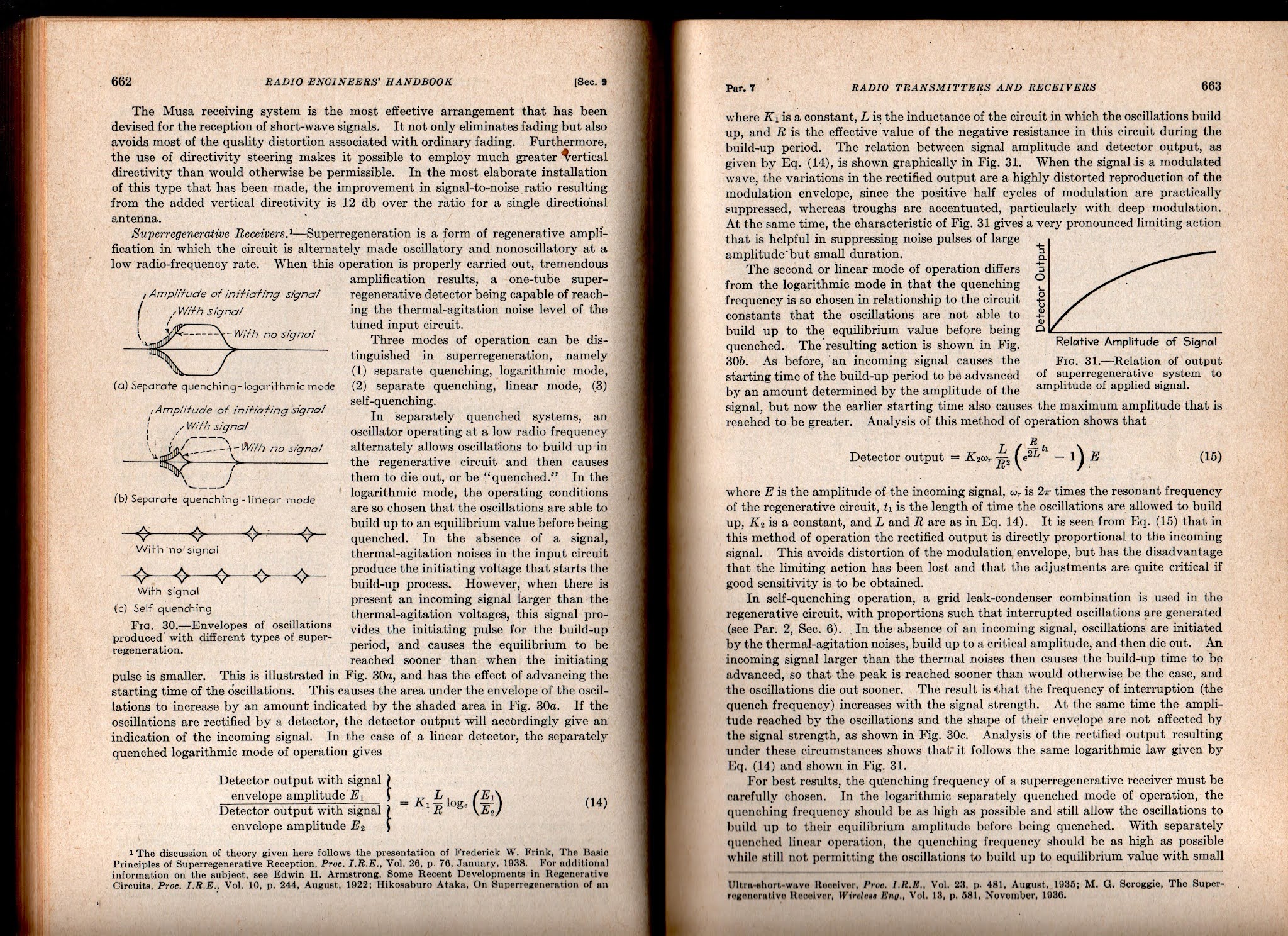
But the best so far (for me) is from Frederick Terman (one of the founders of Silicon Valley) in his 1943 classic Radio Engineer's Handbook. Click on the images for a clearer view.
I will definitely try to get the HW-30's 5 watt AM transmitter going. I am not so sure I'll do anything with the receiver. I think this is a matter of picking your battles and "finding joy." I didn't find joy in FT-8, so I stopped working with it. Same with my HA-600A, DX-40 Novice rig. Same with CW in general. And the same with SDR. I suspect that super-regen receivers may also fall into this category. I mean, let's face it, if you are not fond of ordinary regens, is there any real chance that you will like SUPER-regens? Even Frank Jones seems to have disliked them. And there is a reason Howard Armstrong moved on to superhets -- they are better! But still, that receiver is hissing away at me... Stay tuned.
In December 2021 we will reach the 100th Anniversary of the famous Transatlantic Test that marked the first crossing of the Atlantic by radio amateurs. The video above provides a really excellent description of the momentous event. A few things struck me:
-- Even then they struggled with amplifiers that wanted to oscillate.
-- Armstrong should have gotten more credit for the transmitter design. After all, it was his regenerative system that gave rise to the kind of oscillators that allowed for CW (vice spark) and that formed the basis of the MOPA transmitter that these fellows used.
-- The info on the Superhet receiver used by Paul Godley in Scotland was really interesting: It used "resistance-coupled amplifiers without transformers," similar to what we have today in Farhan's BITX transceivers.
-- Wow, Harold Beverage himself! And his antenna was used at the Scotland receiving station.
-- "It was a miracle that no one got mixed up with the high voltage." Indeed.
The Antique Wireless Association has built a replica of the 1921 transmitter. The video below shows it being tested.
On December 11, 2021 the American Radio Relay League, The Radio Club of America and the Antique Wireless Association will recreate these historic transmissions on 160 meters near the same location that was used in 1921, using a replica transmitter constructed by volunteers at the Antique Wireless Association. This special event is your opportunity to relive a historic moment in amateur radio history.
The operating schedule and frequency for the 1BCG Transatlantic Tests Special Event has not been established.
Additional details will be posted here when they are available.


.webp)