Podcasting since 2005! Listen to Latest SolderSmoke

Sunday, July 5, 2020

The Ceramic Spurs (not a rock group)


Paul Taylor VK3HN's magnificent AM receiver was the inspiration for my Quarantine-31 Shortwave Broadcast receiver.  Like Paul I decided to make use of ceramic filters at 455 kHz for selectivity.  I started with the +/- 3 kHz filters that Paul used, but I found them kind of narrow for SW listening.  So I went with some wider ceramic filters that Bruce KK0S had sent me.  But I misread the specs that Bruce sent.  I thought they were 10 kHz wide filters. I realized later that they were +/- 10 kHz -- really twice as wide as I needed.  So I went back to Mini-Kits in Australia and got some +/- 6 kHz filters.  12 kc wide should be just about right, I thought. 

The bandwidth was right, but I started noticing a problem:  I could hear strong SW broadcast stations at two places on my dial.  This brought to mind an admonition from R.A Penfold, author of "Short Wave Superhet Receiver Construction" (1991 Babani Publications).   He advised keeping a few standard 455 kc IF cans in the circuit because, he warned, the ceramic filters have spurious responses, spurs that the IF cans can help knock down.  

Penfold was right.  Look at the filter response curve on the right (above).  There is a nasty spur at around 640 kHz.   This was the cause of my problem. Here is why: 

Suppose I was tuning Radio Marti's big signal on 9805 kc.  My VFO would be running at 9350 kc. 
9805-9350=455.  Great, but... 
With that spur at 640 kc, I could tune down to 9620 kc on my dial.  My VFO would be running at 9165 kc. 
9805-9165=640.  Bad.   That 640 kc difference product would make it through to my detector and AF amp.  I'd have Radio Marti showing up in two places.  I didn't like this. 

I thought about putting a series LC circuit tuned to 640 kc at the output of the ceramic filter.  This looked like a possible solution, but on the bench it looked like I would have trouble getting a circuit of sufficiently high Q.  

So rummaging around in my junk box I found an old Murata CFM455B filter.  This filter is quite broad, but it does not have the spur at 640 kc.  I could use it as a kind of roofing filter just ahead of the +/- 6 kHz filter.  Putting it there would allow me to avoid having to build additional matching circuits for the 455B filter.  

+/-6kc filter upper left,  455B wide filter to the lover right. 

I'm happy to report that this fix works.   The 6 kc filter provides the needed selectivity, and the broader 455B filter knocks down the 640 kc spur. 

Beware the Ceramic Spurs!  

Q-31 with can for first IF amps and filters open


Tuesday, June 30, 2020

A Backyard Pandemic Field Day in France (Smoke Released!)


Thank you Alain! 

-------------

Hello Pete and Bill,

As you know I am a great fan of your blogs. The fields days are not usual here but because our both countries have been hard hit by the Covid I felt good to participate in this kind of (solo) activity.

My wife Patricia shot 2 pictures for you.

I did some QSO with my callsign followed by FD, but in my enthusiasm I pushed a bit the pressure on my small TX and the PA Mosfet went promptly to the sky...

As you will see, even my dog Guerlain (no callsign) participated...

Hope that you enjoyed a great FD.

Take care my friends.

73 Alain F4IET


Monday, June 29, 2020

SolderSmoke Patreon -- What We Will Do with the Money


I mentioned our Patreon fund-raising effort in Podcast #223.  We immediately got a number of new sponsors.  Thanks!  We also got a question:  "Hey Bill, what are you going to do with all that money?" In the spirit of SolderSmoke full transparency, I will attempt to answer that inquiry right here and now: 

All funds will be used at the discretion of SolderSmoke management.  

Possible (likely) uses include: 

-- Buying air time on shortwave broadcast stations so that the SolderSmoke podcast can be transmitted over the airwaves. We dream of stealing listeners from Brother Stair.   

-- Computers.   From time to time we need to upgrade. This 486 machine is getting kind of rickety. 

-- Paying fees to our internet service providers and to the server that hosts our podcast. 

-- Contributing to worthy charitable causes, including the Color Burst Liberation Army (CBLA), and the Constructor Crusaders.  

-- Buying audio gear we use in the podcast like the really cool microphones that have DRAMATICALLY improved our audio.  No more baby-wipe pop filters for us! 

-- Legal fees to the law firm of Dewey, Cheatam and Howe to fend off law suits, many of which are related to our obstinate use of 60/40 solder, and to our occasional use of images that SOME PEOPLE find offensive.   We also need to pay legal fees to fight our long-contemplated expulsions from the QRP Hall of Fame (Pete is especially vulnerable here). 

-- Magazine subscriptions (to those few remaining publications that have not pissed us off ).  

-- Buying stuff we use in video production (cameras, tripods, lights etc.) 

-- Further development of the SolderSmoke 401k Retirement fund.  We currently invest in Drake 2-Bs, SSDRA books, Hallicrafters S-38Es, 3579 kc crystals, and other items sure to rise in value over time. 

-- Buying gear we will talk about on the podcast or in videos (like the NanoVNA).  

-- Parts.  Si5351s and Raspberry Pi's for Pete.  2N3904s and J-310s for Bill.  

-- A new effort to assist electronics manufacturers in China with product name selection.  "Mean Well" is just not a good name for a voltage regulator.  And "FeelTech" does not bring to mind a signal generator.   For a fee, we can help!  

-- Travel.  If this ever becomes possible again, we need to get to India to meet up with Farhan.  This will undoubtedly result in some awesome podcast/blog/video material.   We also contemplate trips to the UK, Italy, Australia, China and New Zealand.  But we still probably won't go to Dayton. 

-- Buying miscellaneous tools, test gear, books, solder, rosin etc. to be used in the podcast, the blog, and in video production. 

-- Buying stuff for carefully selected new homebrewers (people who will not sell the stuff we give them and then use the money to buy Baofengs). 

-- A new Baofeng buy-back program.  You know, like for assault rifles, but for VHF/UHF walkie-talkies instead. 

We seek your input!  What else should we do with the money?  

DK7IH Improves his Shirt-Pocket Transceiver


More great stuff from Peter DK7IH.   He recently made some improvements to his "Shirt-Pocket SSB Transceiver.  On his blog he explains why he made the changes.  Note the Si5351 that is in there now.  I liked the 1 cm square T/R unit that Peter wrapped in heat shrink tubing. He also provides a really nice description of how to do front panel labeling with a laser printer.


Thanks Peter!

Saturday, June 27, 2020

SolderSmoke Podcast #223 Field Day, Club Talks, Patreon, NanoVNA, Farhan Video, SPRAT, BIG MAILBAG


SolderSmoke Podcast 223 is available: 


27 June 2020

Quarantine Field Day!   
Ironically, THIS YEAR we are both participating
Pete's FD Plan, Bill's FD plan 

Talking to Clubs: 
Pete's talk to the Cedar Valley Iowa Club
Bill's talk to the Vienna Wireless Society

Pete's Bench
DDC SDR
Ideas from the Summer SPRAT
Mean Well Voltage Regulator

SHAMELESS COMMERCE DIVISION: PATREON.   SS is an  SV DELOS WANA-BE!
We got our very first Patreon Patron!  Jonathan Magee from the UK!  Upper Left on the blog.
Continue to use our site for your Amazon purchases. 

Bill's Bench
NanoVNA
Understanding L Networks
+/- 6kHz Ceramic filter for Q-31
Lobes, Nulls and WSPR

Miscellaneous: 
Farhan's feedback Amplifier Video
British Antarctic Broadcast heard (sort of)

MAILBAG:
Mauro VA6BRO liked the SolderSmoke book.  Thanks Mauro
Tryg in Galway Ireland is listening.  Hope to get you the signed books Tryg. 
Michael N4MJR suggested that I use N2 Corona Quarantine Radio as my phonetics.  I dunno... 
Ed DD5LP has been helping us get SS rebroadcast on a German SW broadcast station. Stay tuned! 
Rogier PA1ZZ in California sent an e-mail about the Don Lee Broadcast System.  Thanks Rogier!
Rick KE3IJ  Silver Skirt on his 2B also. W3GOO did it.  Rick traded his Commodore 64 for the 2B.  Yea! 
Walter KA4KXX has a simplified circuit for the MMM!  From UK
Peter VE1BZI thank us for the tribal knowledge.  Dipolo Crilolo
Peter VK2EMU Wee need someone to make the Constructor Crusader badge. 
Scott KA9P sent us the Amateur Wireless cover from 1934 with the Constructor Crusader thing. 
John GM4OOU Built lockdown rig.  we want pictures! 
Jerry KI4IO  His version of the Sproutie by AA7EE   FB 
Adam N0ZIB built a MMM
Wouter ZS1KE in South Africa -- comparing notes on Drake 2-Bs
Randall KD5RC wants to get started in HB. 


Thursday, June 25, 2020

Pete Juliano's Presentation to the Cedar Valley, Iowa Amateur Radio Club (Slides)


Earlier this month Pete N6QW spoke via Zoom to the Cedar Valley,  Iowa Amateur Radio Club.  This was an especially appropriate venue for Pete, the creator of the KWM-4;  Cedar Rapids was the long-time home of Collins Radio.  Many of those in the club used to work for Collins. 

Here is Pete's PowerPoint presentation: http://soldersmoke.com/N6QWslides.pptx

Some notes on the event: 

For the Zoom connection, Peter used his Linux Mint computer. 
  
Pete mentioned that Gene Senti,  while tinkering in his basement,  developed the KWM-1.  One of the guys in the audience confirmed Pete's account, but added something: Collins employees could buy ham gear at a discount. Senti bought a brand new 75A4 receiver (commercial price in late 50s was about $900) and he modified it from being just a receiver into a transceiver.  Imagine taking a new radio and doing that!  But when he got it working,  Art Collins came over to his home to see the invention. The rest is history.

Pete got grilled a bit on why he was still using “analog’ front ends on his several SDR builds -- why not Direct Digital Conversion?   Pete says he may now try to build a DDC rig. 

There was also a lot of very nice feedback on the SS Podcasts – there were many regular listener’s in that group. 

You can see Pete's slides here:  

http://soldersmoke.com/N6QWslides.pptx

Wednesday, June 24, 2020

Arduino, Si5351, GPS linked atomic clock, GPS disciplined frequency counter and more...


Wow, it has been a while since I first talked to Rick, N3FJZ.  Above you can see his QSL card.  And here is a link to a SolderSmoke blog post (with videos) that describes our Homebrew to Homebrew contact:

The e-mail below shows that Rick continues to melt solder, bringing into his rigs some very cool technology:  atomic clocks, GPS modules, and color displays.  That's a long way from the original PTO Direct Conversion receiver that he first heard me with.  FB Rick! 
--------------

Leif, 

I've made great progress on my Arduino Mega 2560 based rig controller I call the ZX-Front-Panel. I just finished a feature I always wanted which is a built-in *GPS disciplined frequency counter*. It uses the 1-pulse-per-second timing output from the GPS module to create a frequency counter with atomic-clock accuracy. It's on the solderless breadboard with the rest of the ZX-Front-Panel right now, and even so, it can count up to 30MHz with no trouble! and it should be able to count up to 100MHz or more if built on a ground plane with a little shielding. The best part about it is that it only required one additional chip (a 74LV8154 32-bit counter $1 from Mouser) in addition to the existing parts already on the ZX-Front-Panel; i.e. the Arduino Mega 2560 ($10), the Ublox NEO-6N GPS module ($15), the display ($25), and the Si5351 PLL RF Oscillator ($8). 

Check out my video series covering the ZX-Front-Panel development progress. The first link below will bring up the video page on my website with the latest video at the top, so you'll have to scroll down a bit to get to the earlier development stages. Check out the rest of the website too for the schematics of my Bitx / TIA inspired rig design (which I call the ZX-SSB-II) that I used an early version of to make my first HF HB2HB contact with Bill (N2CQR) back in 2014 or so (Bill and Pete, via the Soldersmoke podcast, were my inspiration to build my first SSB homebrew rig). 

YouTube videos: http://www.remmepark.com/circuit6040/ZX-SSB-II-Front-Panel/ZX-SSB-II-Front-Panel.html#video 

Homepage: http://www.remmepark.com/circuit6040/index.html

Dean AC9JQ and I have been communicating via emailing about his progress in building his own copy of the ZX-Front-Panel, and I'm very excited to learn that he might be thinking about producing a future homebrew rig featuring the ZX-Front-Panel as its controller/VFO. The best thing about the ZX_Front-Panel is that ounce you install the sketch into the Arduino Mega, you don't need to modify the Arduino sketch itself when you build your rig; i.e. the SSB crystal filter's center frequency (the I.F. frequency), the Si5351's clock output drive level, the display brightness and contrast, and the Si5351 crystal correction factor (crystal trim) are all configurable, real-time, right from the ZX-Front-Panel's user interface, and once set, can be saved to the Arduino's non-volatile EEPROM to be automatically loaded on the next power-up. Also, since it has a GPS module, it features a UTC/Local real-time clock with atomic clock accuracy too. 

Anyway that's all for now, take care Leif. 

73 Rick.

Monday, June 22, 2020

Feedback on Farhan's FB Feedback Amp Video


As I said a couple of days ago, Farhan has put out a very informative video on amplifier design. During the video we can see him determine bias, feedback and load levels, then select component values. We then see him actually build the amplifier "ugly style" and use his Antuino to test it.  Fantastic.   

Watch Farhan's video here:  https://www.vu2ese.com/index.php/2020/06/18/feedback-amplifier/


I sent Farhan some of my reactions to the video.  In the hope of stimulating some discussion, I repeat them here: 

___________________

Wow Farhan, I really enjoyed your video and learned a lot.  You definitely have the Knack for explaining this stuff. 

I have been struggling to understand feedback amps for a long time.  I took up this topic on pages 187-190 of the "SolderSmoke -- Global Adventures" book.  I was more focused on the benefits of FB amps, and on how and why feedback affected input impedance.  

 I took notes as I watched: 

-- I liked the fulcrum analogy. 

-- Really wonderful how you describe the selection of components to get desired bias. 

-- Even better when you explain tapping down of RF coil to get 50 ohms to look like 200 ohms. Great stuff. 

-- Standardized on BNC.  FB! 

-- .1uF caps.  Love them!  No argument here! 
 
-- I copied your resistor list.  Will use it with Mouser. 

-- Saving the pigtails.  Indeed!
 
-- I like your ugly "resistors first" technique.  I may have to move away from Manhattan. 

--  Wow.  Ugly circuits IN SPAAAAACE!  FB!
 
--  2N3904   I always think it is EBC when looking at the flat end of transistor with leads facing down. Only had reverse pinout with PN2N2222.  EBC is my usual assumption.
 
-- I still have the big box of trifilars you left me.  I use them.  Thanks!

-- I like that VTVM in your Antuino.   Very handy. Want one!  Also, We need to get the Antuino to go down to below 455 kHz. 

-- I also like your dual Return Loss and SWR display.  I think in terms of SWR.  Return Loss sometimes messes me up. 

-- Didn't know about the Hold and Zoom feature on Antuino. FB.
 
-- Your measurement of the Q of the crystal was awesome.
  
-- I checked my soldering iron temp:  I'm at 480 C   A bit too hot. Will back off. 
 
-- Good description of need for an attenuator at amp output to keep it in Antuino's range.
 
-- As I watched you tug on the components after the solder cooled, I remember an old and silly admonishment from the ARRL Handbook:  NEVER  use solder for mechanical connections.  Ha!  They were WRONG!
 
-- Demonstration of the flatness of feedback was great.
 
-- I found your measurement of impedance using the SWR feature of the Antuino to be very useful.  Is there a chart relating the SWR/Return Loss to actual impedance values? 

-- Loved your description of how output impedance affects input impedance.  That is why you advised use of TIA amps in my DIGI-TIA.   But now I'm thinking that if I can accurately measure impedances of non-TIA amps, I can design L networks that will keep the crystal filter passbands ripple-free, right? 

-- Great explanation of the benefits of the 6 db pads at amp output.  Allison often recommends this. Now I know why. 

-- Wow!  Now I KNOW what that two-tone box you left with me is for!  Now I understand how it can be used to measure IMD on FB amps.  I pulled mine out just as you began to discuss yours.  Really cool. 

Thanks a lot Farhan for doing this.   These videos will be of long-lasting use to homebrewers around the world.  I hope we will see many more VU2ESE videos like this one. 

73  Bill 

Join up NOW!


From the front cover of the July 14, 1934 issue of Amateur Wireless.   This UK weekly magazine was the predecessor of Practical Wireless. 

Saturday, June 20, 2020

Excellent Video from Farhan on Amplifier Design


Farhan has produced a really excellent video explaining the theory behind the feedback amplifiers that we use in so many of our circuits.  He takes us through the design and construction of these amplifiers, then uses his Antuino network analyzer to test an amplifier  and to measure input and output impedances.  

There is a lot of tribal knowledge and wisdom in this video! 

Check it out here:  

https://www.vu2ese.com/index.php/2020/06/18/feedback-amplifier/

Thanks Farhan! 

Thursday, June 18, 2020

You must join the CONSTRUCTOR CRUSADERS


Wow. This 1934 front-page presages so many things that we talk about today. 

"The Constructor Crusaders,"  reminds me of "The Color Burst Liberation Army."

"Wear the badge and be in fashion," is clearly just another way of saying "chicks dig it," and brings to mind Pete's beret. 

Finally, "Constructor Crusaders will get the best out of radio!"  Well, that's what we've been saying all along.  

Note that as early as 1934 they were talking about TV:  "Radiovision."

Thanks to Scott KA9P for passing this to us. 

Wednesday, June 17, 2020

Lobes, Nulls, and "Gain Dipoles" -- Testing the Theory with WSPR

In the last podcast Pete and I were discussing dipole antennas.  We mentioned dipoles that were multiples of 1/2 wavelength and said the result could be a "gain dipole."  This provoked some head scratching.  Listener Riley asked for more info. See the comments section under this post: http://soldersmoke.blogspot.com/2020/05/soldersmoke-podcast-222-antennas.html

A short time later Pete was corresponding with Brad WA8WDQ who had questions about his antenna pattern.  Pete recommended using WSPR to test his antenna's effectiveness. 

These two exchanges got me thinking about the radiation pattern of my 135 foot doublet antenna, especially on 20 meters.  Where are my lobes, where are my nulls?   Following Pete' advice I turned to WSPR.   But first, a quick look at the PREDICTED patterns.

ON5AU has on his site a great article by antenna guru L.B. Cebik  W4RNL with exactly the info I needed.  Above is W4RNL's chart of predicted radiation pattern for 20 meters on a 135 foot doublet.  Note the orientation of the wire.

My antenna is oriented almost exactly north-south (broadsides to the east and west).  So with a standard north at top map, my pattern on 20 should look like that of W4RNL's chart.  What did I get from WSPR?   Here is the pattern for an hour or so of 250 milliwatt transmissions from my station using the 135 foot doublet on 20 meters (using homebrew balanced tuner): 


You can clearly see at least three of the four predicted lobes (NE, NW, SW). 

Now, part of this WSPR pattern could, I suppose, be the result of the geographic distribution of WSPR stations.  If there are just more of them in the areas where I am seeing lobes, the pattern could just be the result of geographic distribution.   I don't think that is the case, but to test this idea (a bit) I decided to look at the 40 meter pattern.  

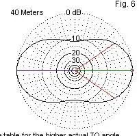
Here is what W4RNL predicted (same north-south antenna orientation): 


And here is the WSPR map that I got, again using about 250 milliwatts for about an hour): 


I think this pattern matches nicely with the prediction.  You don't see the nulls that you see in the 20 meter pattern.  You do see some stations directly north of me (as predicted).  There does not seem to be a big disparity in the geographic distribution of WSPR stations.

One note on the use of WSPR:  I started out using WSPR in receive mode, thinking that the pattern I'd see would be similar on receive or transmit  due to the antenna reciprocity principle.  But I worried that the results could be easily skewed by higher power WSPR stations.  So I shifted to the transmit mode and limited my output to 250 milliwatts. 


Here is the W4RNL chart showing the patterns for all the bands: 


Here is the azimuth chart for my location: 


Designer: Douglas Bowman | Dimodifikasi oleh Abdul Munir Original Posting Rounders 3 Column