Podcasting since 2005! Listen to Latest SolderSmoke

Monday, November 15, 2021

SSB History: Selling SSB in 1954


K9YA Telegraph ran (on Facebook) this ad from 1954.  It provides an interesting view of where phone operations were in that year.  Note that Dale was so intent on selling SSB gear that they were willing to make on-the-air schedules to demonstrate SSB superiority.  

Dale claims that with SSB you could have TWO roundtable QSOs on the same frequency, with one group on USB and the other on LSB.  I think this assumes really great opposite sideband rejection in the transmitters, and excellent selectivity in the receivers. That might have been a bit of a stretch.  But the assumption here was that hams could use USB or LSB -- no rigid adherence to the USB/LSB convention.  And the ad seems to focus on the 75 meter band which was seen as the most important phone band at that time. 

Dale was selling Collins mechanical filters for 55 dollars.  That is the 1954 equivalent of $566 dollars today.  No wonder the phasing method was so popular.  Note that they were selling Central Electronics phasing rigs right next to the ad for the Collins filters. 

I like the graph showing opposite sideband rejection with the Sideband Slicer.  Note that the selected sideband was referred to as the "exalted" sideband.  All Hail the Single Sideband!  

Saturday, November 13, 2021

"First Wireless" 1922 book by Allen Chapman with Foreword by Jack Binns (free download)


The cover caught my eye.  Thanks to the K9YA Telegraph for posting it.  I think it captures the allure of radio that most of us felt when we were kids of this age.  

Fortunately this 1922 book is available for free download: 

It is all about radiotelephone.  They are phone guys.  Just like us.  

And they were homebrewers.  They had The Knack. From Chapter II: 

Another thing that drew the boys together was their keen interest in anything pertaining to science. Each had marked mechanical ability, and would at any time rather put a contrivance together by their own efforts than to have it bought for them ready made. It was this quality that had made them enthusiastic regarding the wonders of the wireless telephone.

And they correctly viewed wireless telephony as being similar to Aladin's lamp.   I remember writing that my homebrew DSB transceiver was like Aladin's magic carpet, carrying my voice from the Azores to friends around the world.  From Chapter III: 

They had already heard and read enough of the wireless telephone to realize that it was one of the greatest marvels of modern times. It seemed almost like something magical, something which, like the lamp of Aladdin, could summon genii who would be obedient to the call.


This is a reminder of how young the radio art is.  This book came out just three years before my father was born. Many of us have in our shacks working rigs that are half as old as radio itself. 


Friday, November 12, 2021

Mate for the Mighty Midget with 6 kHz Ceramic Filter


I built this receiver back in 1998, but I continue to have fun tinkering with it. I wrote an article about it for "Electric Radio" magazine (Number 115).   One of the major shortcomings was the crystal filter that Lew McCoy prescribed.  It was very difficult to get 455 kHz crystals to work well as filters.  At various times I've had all kinds of replacements in there in place of Lew's filter:  a 455 kHz IF can, a Toyo CM-5 hybrid ceramic filter, a fancy Millen high Q IF transformer. None of them really worked well. 

Recently I put a little +/- 3 kHz ceramic filter in there.  This is a 6 kHz wide filter at around 455 kHz.  I think it works really well.  Above you can see the receiver in action.  I use it with a little powered computer AF amplified speaker -- I just don't like headphones.  


The latest  filter mod with the 6 kHz ceramic filter  is shown above. 


Above you can see what the whole 455 kHz filter and transformer passband looks like. The input was through a 2k resistor placed between the .001 uF cap and the filter. The output was also through a 2k resistor placed at the top of the secondary of T1. (So don't pay any attention to the insertion loss.) 

The NanoVNA is displaying 2 kHz per division.   I put the BFO at 451 kHz.  This results is excellent opposite sideband rejection.  The filter is really too wide for SSB, but it is about perfect for AM, which I listen to quite often on both 75 and 40.  SSB and AM both sound quite good.  Check out the video above. 

It is kind of amazing what can be done with just three 6U8 tubes. 

There are many previous SolderSmoke blog posts about the Mate for the Mighty Midget Receiver here:
https://soldersmoke.blogspot.com/search?q=Mighty+Midget   Be sure to keep selecting "earlier posts" so see more. 

Thursday, November 11, 2021

Scott WA9WFA's Beautiful HBR-13 Receiver (3 videos)

This is Scott WA9WFA's first homebrew construction project.  He did an amazing job on a very complex project:  a 13 tube superhet receiver.  It features plug-in coils for multi-band coverage, dual conversion with IFs at 1600 kHz and 100 kHz, and several regenerative stages.  Scott's construction is top notch. He tells us that he had been working on this receiver for several years, so long in fact that some of his friends began to wonder if it really existed.  Well wonder no more.  Retirement has provided Scott with the time to finish this project. 


I like the way Scott talks about the project in these videos.  He puts it in the context of his long-standing goal of building his own high quality ham station.  With the HBR-13 done, he is more than halfway there.  We all know that the receiver is the hard part.   

I agree with those who say that Scott should keep the plexiglass front panel.  I think it looks very cool.  


In the third video, Scott takes us on a cruise through the 40 meter band.  The receiver sounds great.  Lou EA3JE's booming voice came through quite nicely from far-off Barcelona. 

Congratulations Scott on building a truly outstanding receiver. And on making some great videos. 

There is some additional background info on the HBR-13 in this blog post from back in September: 

Wednesday, November 10, 2021

Right to Repair Update

Allan WA9IRS sent me this article.  Thanks Allan.  

https://www.digitalengineering247.com/article/right-to-repair-movement-attracting-attention?oly_enc_id=4802E9408878H3Y 

The French "repairability index" is an interesting concept.  I wonder how modern ham radio "radios" would score. I think our homebrew rigs would max out the index. 

Pete has commented on manufacturing processes that do (or don't) factor in access for repair. 

One of the recent horror stories we've heard is about a certain manufacturer of mobile phones.  It seems that they have designed the phones so that if you dare to replace a broken screen, the new screen won't work unless you de-solder the associated chip, then re-solder in the SAME CHIP.  

Previous blog posts on this: 

https://soldersmoke.blogspot.com/2010/11/knackers-of-world-unite-you-have.html

https://soldersmoke.blogspot.com/2021/03/mending-vs-ending-fight-against-planned.html

Tuesday, November 9, 2021

Zigbee Radios on the Ingenuity Mars Helicopter


In his recent interview with Eric Guth, Courtney Duncan N5BF told us that the communication between the Ingenuity helicopter on Mars and the Perseverance rover is being handled by off-the-shelf Zigbee 900 MHz transceivers.  

I did some Googling and found some more details on this: 

----------------------------

"Once separated from the host spacecraft (lander or rover), the Mars Helicopter can only communicate to or becommanded from Earth via radio link. This link is implemented using a COTS 802:15:4 (Zig-Bee) standard 900 MHz chipset, SiFlex 02, originally manufactured by LS Research. Two identical SiFlex parts are used, one of which is an integral part of a base station mounted on the host spacecraft, the other being included in the helicopter electronics.


These radios are mounted on identical, custom PC boards which provide mechanical support, power, heat distribution,and other necessary infrastructure. The boards on each side of the link are connected to their respective custom antennas.


The helicopter antenna is a loaded quarter wave monopole positioned near the center of the solar panel (which also serves as ground plane) at the top of the entire helicopter assembly and is fed through a miniature coaxial cable routed through the mast to the electronics below. The radio is configured and exchanges data with the helicopter and base station system computers via UART.


One challenge in using off-the-shelf assemblies for electronics systems to be used on Mars is the low temperatures expected on the surface. At night, the antenna and cable assemblies will see temperatures as low as -140 C. Electronics assemblies on both base station and helicopter will be kept “warm” (not below -15 C) by heaters as required. Another challenge is antenna placement and accommodation on the larger host spacecraft. Each radio emits approximately 0.75 W power at 900 MHz with the board consuming up to 3 W supply power when transmitting and approximately 0.15 W while receiving. The link is designed to relay data at over-the-air rates of 20 kbps or 250 kbps over distances of
up to 1000 m. 

A one-way data transmission mode is used to recover data from the helicopter in real time during its brief sorties.When landed, a secure two-way mode is used. Due to protocol overhead and channel management, a maximum return throughput in flight of 200 kbps is expected while two-way throughputs as low as 10 kbps are supported if required by marginal, landed circumstances."


A citation for the above quoted text: https://trs.jpl.nasa.gov/bitstream/handle/2...L%2317-6243.pdf I believe.

A more detailed reference for the telecom system with some good detail about the helicopter in general is https://trs.jpl.nasa.gov/bitstream/handle/2...L%2318-3381.pdf

----------------------------

Data Sheet from Mouser: 

Monday, November 8, 2021

Did You Contact My Novice Station WN2QHL in 1973-1974? Please Check My List and Let Me Know

Yesterday I went through my novice logs from 1973-1974.  I was in Congers, NY and my call was WN2QHL. Please take a look at the callsigns from my log and let me know if we had a contact.  I will then let you have more details from my log. 

Novice Contacts 1973-1974 from WN2QHL

WN2NEC

WN2RTH

WA4DCL

WN4CBB

WN9LLX

WN1RWX

WN4ETR

WB2CSO

WN8QHM

WN8ONA

WN4KID

WN8PMF

WN2INN

WN2ECU

WN4DSO

WN3UCL

WN4KBL

WB4WDQ

WN0IHH

WN9MNW

WN8ODW

WA8VCH

VE1BAD

WN8NIJ

WN8MYJ

WA3TKP

WN2GMQ

WN8LDI

WN5JZP

WN5JXZ

WN2PNQ

WN2HKY

WB2PPP

WN4EIS

WN4DNV

WA8WIK

WN3TPJ

WN1RRR  WN1RPR?

W2MJR

WN2SHL

WN3TZR

W1DUQ

WN2ROW

WN2SLA

WA3HNZ

WN2JXT

W2HAG

WA2CDE

WN8ORL

WN4FYL

WN1PXM

WN2FPQ

WN4ZFF/3

WN3VDU

WN8QPJ/8

WN3TBW

WN4BWT/4 OR BWJ

W9MZO/9

WN1SLG

WN0KTR

W9KCT

WN3VKH

K1BXZ

W1AW

WA2QNX

K2BBU

K1BXZ

WN2ROZ

W1TRS

VE3FMF

WN3UPO

K1OOL

WN2RNJ

WN2KWK

WA2CDE

WN2JDE

WN3UQO

WN2IZY

W3CNN

WN2NNA

WB2EVS

VE2AJQ

WN1SBE

WN4ZIN

WA2JXM

WA3TVE/3 OR JVE OR UE

WASQWF

WA3JRU

W3ABT

WA2IWX

WN3FLK

WN1RZW

WN3TBW

WB2PYM

WN1RXM

WN2ERU

WB8HHN

WN2LVV

WB8JBM/8

WN2TEO

K4LDR

WN2EHE  Friend of KD2E Dave

K8MFO

WN2NAE

W3IN

WN3SZX

WA1EOT

W2MUM

WA2UOO

WB2RKK

W4KFL

WN2NEC

WN4EJJ

WN1SCL

WN2NQL

WA1RXJ

WA2YAS

WN2QHN

WN8POK

WB2ABJ

WN1QKD

WN2SDO

WN1SRT

WN2KOH

WN8DOB

WN1SQM

WN2SXT

W2HN

WA1RFF

WN2VNA

WN1RME

WB4YNY

WB8ALE

WN4AQM

WN4DMO

WN3USU

WN8NXE

W2HAG

WA1KLB

WB2NDL

WN2JXG

WN1RIP

WN2LKN

WA3IYA

WB9LJS

WN2RPL

K1BOM

WN4GOC

WN8QGO

WN8OPB

WN8OOE

WN2SAM

WN4FXN

WB2SXD/2

WN2IQM

WN3VUU OR UUU?

WN8PGD

WN8PIU

WN8OGY

WN8OWD

WN8OHP

WN9JOI

WN2GMQ

WN3VUR UR UUR

WN2LOC

WN2SAM

WN2TJQ

WA43PM

WA4YDR

WN9LDS OR LOS

WN9LSR

WN3UDR

WN1RGU

WA1RYL

WN2LBO

WN1RIM

WN2TAG

WN2TLQ

WN8ODP

WN2TBB OR JBB   now Dave KD2E 

WN4CRZ             First QSO with DX-100

WN4HKG

WA6TLH/HK6         FIRST DX  40 METERS   Feb 23 1974

WN2JHP

WN2TAS OR JAS

WN8QXR

W4DRJ

WN4GBX

WN4DAQ

WB8KUQ

WN4BPN

WN2SAM

WN8OVW

VE3GXX

WN0JOZ

WN6CPQ

WA4CNL

WN0LLT

WN0KUU OR KVU OR KUV

WN8QIN

WN4HLQ

K0IEU

WA1DWL

WN4GUF

VE1IC

WN4FOM

K2AVX

WA9AKY

VE2DJB

WN4EDQ

WN8PLH

WN2TPD

WN1SZS

WN4HRC

WA0WTV

VE3HEF

WN3UOO

K2IY

W4AHN

WN8OIF

WN9NYO

VE3AFX

K1PNB

K5EQX

WB6ALD

WB6LUS

WN0LQE

WA1POJ

WA5RFT

WN8NYU OR V

WN4GUF

K1BXZ

WN5GTE

WB5GDN

WB5GEN

WN2TJQ

WN2JXT

WN4CQX

WA1ASU/1

WN2IOJ

WN4GMY

WN2RUZ

WB8PRJ

WN4BTL

WB8MOI

VE3AGY

W8JEI

WN3VUZ

WA2CME

WN5KYK

WA1JUY

WN2NIL

K3DHD/9

WN4CTJ OR CWJ OR WUJ OR CVJ Gadsden AL.

WP4DRE/5

WN2GMQ

WN1SIP

WN9MOS

WN9OCO

WN2UAC

WN8NPY

WB5DIZ

WN2JHD

WN2RYH

WN2RXL

WB8OFU

WN8RTU

WN8MTW

WN8PIY

WA8JPC

K1OOL

WB2MYV

WN4CNE

WN4DXW

WN2PHE

WN8MYJ

WM2TTQ

WN4AYX

WN4ECB

WNOJGT

W4UHF

WN4FPU

WN8QCV OR U

WN8PCV

WN2STZ

WN2KLX

WN2FUN

WN2SLF

WN8RTZ/9

WN9MLY

WA7SCG

KP4USN

WN2UMV

WA6ARG

WA4BPS

WN9MAO

WN5HRI OR 4

WN2PWM

KZ5VV

ZL2ACP

WA6UUR OR VVR JACK IN Pasadena

KN5KSX

YU1NFT

YU2QZE

WA7STW

WN8RIK/4

WN2UMU

WN2PNQ

WN2QCE

YU2QZ

WN2TJQ

Save $2970! Build this $30 DIY Microphone!


There are a number of good ideas in this video.  We've known for a long time that many expensive mics are really simple, cheap mic capsules in fancy packaging.  This video takes a $12 mic capsule (which looks a bit like the ones we are using for the podcast), adds come amplification, a USB interface, and some really cool looking bronze packaging to come up with a very nice microphone. 

I liked his use of solder wick as a shield for the DIY mic cable.  Who knew the wick was hollow!  I also like the cooking torch for use in soldering the brass.  I need one of those. The little Murata DC voltage booster with positive and negative output seems useful. 

It seems that anyone working on this kind of project quickly gets pulled into the use of "audio speak." Late in the video Matt says his mic has nice low-end "presence."   A quick look at the comments section shows one person saying that one or the other of the mics sounds a bit "moist."   

There are many other similarly interesting projects on Matt's YouTube channel:

Sunday, November 7, 2021

JPL, Mars Helicopter, Cube Sats, Ham Radio and more: N5BF talks to Eric Guth 4Z1UG


This morning Eric Guth has a really interesting interview on his QSO Today podcast.  
Courtney Duncan N5BF had a full career at JPL and is the current president of the San Bernardino Microwave Society.  There is a lot of interesting stuff in this interview, much of it about space exploration.  Courtney tells us about how experience with re-purposing radio gear came in handy at JPL.  For example, the helicopter that they have been flying on Mars has a very cheap and light off-the-shelf Zigbee transceiver.  He also talks about the origins of the Cube Sats.   

Here is Eric's page on this interview, with useful show notes: 

https://www.qsotoday.com/podcasts/n5bf

I like to listen to Eric's shows on YouTube -- here is the YouTube recording of the N5BF interview: 

https://www.youtube.com/watch?v=Fbr4jE11vfg

Here is N5BF's ham radio web site: 

http://cbduncan.duncanheights.com/HamRadio/HamRadio.html

Here is the club page of the San Bernardino Microwave Society:

http://www.ham-radio.com/sbms/

Thanks to Eric and Courtney! 


Saturday, November 6, 2021

M0NTV's "Crystal Filters for the Fearful" (video)


I really liked Nick M0NTV's approach to making a crystal filter (see video above).  He really simplifies a process that desperately needs simplification. I remember when I was building my first superhet receiver,  I came across Doug DeMaw's schematic for a crystal tester that would allow me to properly build the filter.  But the piece of test gear was far more complicated than the receiver I was building.  I never built Doug's device. 

Nick's technique is simpler even than the G3UUR method that many of us have been using for years.  Nick dispenses -- wisely I think -- with the need to calculate motional parameters, Q,  and equivalent series resistance.  This also eliminates the need to fidget around with the design software such as Dishal or AADE.  

Nick uses the Cohn topology (good choice) and uses kind of an "informed cut-and-try" technique to come up with the capacitor values.  

Filter impedance is determined with series trimmer resistors and the NanoVNA to watch the resulting passband.  Nick says this is a Charlie Morris ZL2CTM suggestion.  It obviously works very well -- the ripple that would result from impedance mismatch is eliminated.  

Nick's determination of the best turns ratio for the impedance matching transformers is brilliant.

Nick apologizes for what he says is a long video.  But it is only 30 minutes or so long, and if you are going to build your own superhet or SSB filter rig, it is well worth watching.   

Three cheers for Nick and for Charlie!  Thanks guys!   

Friday, November 5, 2021

The Importance of Keeping the Noise FLAT


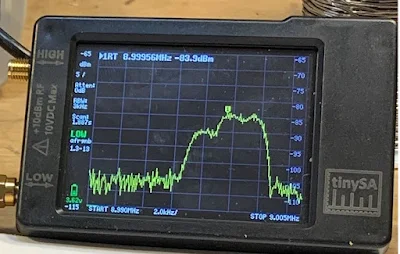
A few days ago I put up a blog post about using a noise generator (in my case my cheap FeelTech sig generator) and my TinySA spectrum analyzer to look at the passband of a crystal filter.  I was using the 9 MHz filter used by Dean KK4DAS and the Vienna Wireless Makers Group.  The idea is simple: insert broadband noise into the input. The filter should pass more of the noise that falls within its passband.  The TinySA should let you see this.  At first, I was pleased that I could clearly see the passband.   I thought I had succeeded.  See above. 

But I was bothered by something.  Look at that bump in the passband.  It should be close to flat across the top.  

I decided to take a look at the same filter with my NanoVNA.  Here I was not using a noise generator.  The NanoVNA sweeps the filter using and looks at output in the Log-Mag mode.  Here is what it looked like (below): 


That was much better.  But why the difference?   Tony Fishpool G4WIF suggested that my noise source might not be putting out noise at the same level on all frequencies.  I took at look at the noise output of the FeelTech sig gen in the range of the filter passband (with some above and below frequencies for reference) and I found that the flatness of this noise depended a lot on what frequency I had the sig gen set to.  I tuned it around a bit until I found a setting that produced a flat noise output in the desired frequency range.  Then I went back and swept the filter with the noise and the TinySA again.  Here is what it looked like with the "flat" noise: 


Better,  I think.  Closer to the passband displayed by the NanoVNA.   

Tony points out that these Chinese sig gens don't really put out random noise -- they give us predictable noise.  Dean said "Predictable Noise" would be a good name for a rock group.   I said they could open for my favorite: "The Ceramic Spurs." 

Designer: Douglas Bowman | Dimodifikasi oleh Abdul Munir Original Posting Rounders 3 Column