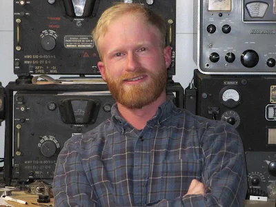
Our Direct Conversion Receiver is being built around the world, but one of the most exotic locations for a build is the island of Bali in Indonesia. There Wayan YD9BAX set out to build the receiver.
Early on, Wayan noted that he would have difficulty getting the 1000:8 ohm AF output transformer we were using. This transformer was easy to get if you have easy access to Mouser, but a few prospective builders in Europe and the U.S. expressed deep objections to our use of this device. Some complained that we should have used a push-pull amplifier. Others complained that they didn't have one of these in their junk box. Some even hinted that we should have gone with an LM386 chip. But we stuck to our plan, noting that the very simple AF amp circuit we had developed would be understandable in ways that the alternatives were not. Still, I worried about Wayan. He might have really been out of Mouser range.
Yesterday the above video appeared. Wayan finished the receiver. It is inhaling nicely on both SSB and CW. The CW signal you hear in the recording is that of YB1IHL. That is CW from Indonesia as picked up by a homebrew recevier. FB!
How Wayan cracked the code on the transformer is inspiring. He essentially homebrewed the part. Wayan wrote on the Discord server:
At last I can hear the CW and SSB coming in. The one and only 9v battery that I have during homebrewing forcing to switch to bench PSU with 9,3v setup Pardon me for the messy board and layouts, excitement that it works with parts I have in hands is everything. I learn a lot during this project, including inability for sourcing 1k:8 audio transformer causing me to build my own xformer from 600 ohm transformer former and magnet wire from a broken relay, tedious works but I learn new things. Need to tidy up and may need to build another mixer and BPF again.
He also homebrewed the PTO coil former.
Wow, that is all really inspiring, and is a great example of the homebrew spirit at work.
Aaron ZL1AUN used his homebrew SolderSmoke Direct Conversion receiver in a 40 meter SSB contact with his fellow New Zealand radio amateurs. His transmitter was a modern commercial rig, but his receiver was the Direct Conversion receiver.
I think Aaron's video is an excellent demonstration of how stable and useful this receiver really is.
The next step for many will be the construction alongside the DC receiver of a Double Sideband transmitter. You could make it with only the receiver PTO serving as the common stage. Just build another mixer, a mic amp, and an RF amp with low pass filter. Switch the DC voltage and the antenna from T to R and you will be on the air, on phone, fully homebrew.
Here is an article describing how I did this on 17 meters in the Azores in 2001:
Lot of success! So far 22 completed receivers: 35 others are being built.200 or so people are on the Discord server.
What a great achievement this is! Folks are homebrewing receivers.
Scott KQ4AOP heard his very first amateur radio signals through this receiver. FB!
Lots of great ham homebrew spirit. NE3U, N9TD and others 3d printing coil forms for others. FB
It is not too late. Dean's videos and the Discord server will remain up, even when we ourselves have moved on.
Big Picture: Farhan's Four Stages -- All you need to build a rig: Oscillator, Filter, Mixer, Amplifier.
Homebrew and Manhattan vs. Kit built with PC board. We think Homebrew is a better experience. Dean recently assembled some Ikea kit furniture. Does that make him a carpenter? No.
We do update the schematic as we learn. This is similar to what happens to software. Github? Version 2.3? In the old days, when QST came once a month, we lived a harder life. We don't have to do that anymore.
Let's talk about the boards one by one:
The Oscillator (VFO or PTO):
-- Started out as an amalgam of Farhan circuits: We liked the very simple oscillator he used in his Hyderabad DC receiver project for the girls schools. No need for a hard-to-find variable cap. But we found we needed a 3.3 k ohm resistor in the emitter to make it go. We took the buffer/amp from Farhan's "Daylight Again" circuit, but later (much later!) added a .1uF cap across the source of the J-310.
-- With brass screw, not really a permeability tuned oscillator. Brass has same permeability as air. Works via Eddy currents. But the screw thing is very reminiscent of the old Collins PTOs, so we call it a PTO. And it IS s PTO if you used a steel screw. You should study the doc in the mods section about how to modify the PTO. Metalurgy matters!
-- We used silver mica caps in the frequency determining circuits. This is important.
The Mixer:
-- We started with a simple two diode, single transformer singly balanced mixer. Only LO signal would be balanced out. This would work, but we got a lot of AM breakthrough from Radio Marti, just above the 40 meter band. So we went with a homebrew diode ring mixer.
-- Important to unserstand how the diode ring really works: LO just switches on and off the diodes. Very cool that several builders sought to understand how diode ring works.
-- Best way to test the PTO and the Mixer? Put them together and look at the waveform at the mixer input. Is it flat topping? Then both stages are working.
-- Diplexer: From QRP legend W7EL's Optimized QRP transceiver. Seemed to help knock down Radio Marti. But we kind of knowingly disregarded AF amp input impedance. It would have been too complex to fix. We were going for simplicity.
BP Filter:
-- We actually got to do the NanoVNA test with one set of the high school students. This was very cool. Proves the worth of the NanoVNA.
-- Again good to learn the theory.
AF Amp:
-- Kind of an amalgam of a Forest Mims amp and the amp from the Herring Aid 5.
-- Sure, an LM386 would have been simpler. But we did not want to use ICs. And IC AF amps oscillate too. You learn more by going discrete.
-- We used a transformer. For simplicity. We know the push-pull circuit, but wanted to avoid it. Some guys are going to other AF amp circuits becasue of the transformer. See this as an interim measure... You can fully meet the challenge later, when you get the transformer.
-- We also -- in the name of simplicity -- did not use feedback amps. We have an optional bandaid resistor across the oscillator to lower overall gain.
-- It can oscillate. But keeping leads short, keeping inputs away from outputs, putting adequate electolytics on the 12V power rail can prevent this. This is a good lesson in good construction practices. And with the real world of amplifiers (they all aspire to be oscillators!)
-------------------
Some Tales of Woe:
Simple mis-wiring – need to learn to read schematics
Transistors in backwards – importance of checking the data sheet for your brand – sometimes different brands of same part have different pinouts
Lying Test Equipment
Jay W3V3 unreliable measurements from old Fluke auto-ranging multimemter
Phil, W1PJE – using a 10X probe with scope termination set to 50 ohms
Peter, VK3TPM – faulty component tester (mixed up collector and emitter on NPN transistor)
And many, many setup issues with scopes, signal generators, TinySAs, NanoVNAs
Bad parts
Some “lessons learned” taken from the Walk of Fame Channel
Wayde, VA3NCA – taking care when choosing junque drawer components, solidifying concepts introduce in the licensing material – benefit of hand-son experience “building them made them more real”
Peter VK3TPM – don’t trust your transistor tester, transistors can pass signals even when wired backwards. Importance of 10X probles. NP0/C0G caps for frequency stability
Ken, W4KAC – learned to better use his test equipment to trouble-shoot, and finally learning to trust his troubleshooting after changing out a faulty transistor.
Parts sourcing: We were surprised at how much time people spent on this. Parts sourcing struggle reminds us of the importance of 1) understanding the circuit and 2) having a decent junkbox. 3) scrounging old parts when necessary.
Looking ahead: Antennas are important! You probably can use Cat 5 cable instead of real coax. Noise is natural. Mods are fun. CW in some ways harder than DSB. Lot of antenna info on the internet.
You can modify the PTO for easier tuning. See the doc. Add a front panel, or a case. Once your basic receiver is done, you can experiment with better circuits. See the mods doc for ideas.
Final Comments:
-- It is ultimately the builder who has to make the machine work. Homebrew means that YOU the builder are going to make it work.
-- Be careful about who you take advice from or give advice to. Don't be afraid to say "I don't know." Ask yourself: Is the guy who is giving me advice really an experienced homebrewer? Am I?
-- We learned a lot in this process. You guys have made this a better receiver.
-- Be careful about starting over... Bill and Dean's homebrew nightmare!
Just 30 minutes prior to this, my wife Elisa happened to see on Instagram a map showing the flight path of the Falcon 9. We didn't know that this was coming! I checked and got a live feed from Cape Canaveral of the launch. I figured we might see something if we looked to the north-west. Wow, did we. The Falcon 9 put on an amazing display. On January 25, 2025 we had seen a meteor-bolide fireball on a similar track. That was quite something, but this was really amazing. You can hear our excitement in the audio.
Thr bright object is Venus. The rocket appears to turn off its engines shortly after (from our point of view) it passes Venus.
Hello Todd! I have been thinking about the same things. As you know there is a lot of magic in using gear that you have built yourself. And it is still possible to do this. But I think the builder has to make some choices: Building it yourself might -- as you say -- require you to move away from the perfection, bells and whistles of the modern ICOM 7300 style rigs while embracing the simple functioning of analog rigs. Farhan was thinking of this three years ago:
"So here we are, talking analog radios in 2022. Here is the memo : The analog never died. The world is analog all the way, until you descend into Quantum madness. The antennas are analog, Maxwell died a content, analog man. Our radios, ultimately, are analog machines and we are all analog beasts too. Amateur Radio technology has evolved into the digital domain. However, it has only made it easier for us to do analog with computers to simulate and print our circuits. So, it’s time to bid good bye to our Arduinos and Raspberry Pis and build an Analog Radio for ourselves. So let’s see what we can achieve in hindsight, a return to our native land and a rethink of our approaches. The radio is called Daylight Again, a nod to being back at the FDIM in 2022 after a gap of two years. It is named after the Crosby, Stills, Nash and Young’s song that had been humming all the time while put this radio together, emerging after 2 years of lockdown. This radio that took two days to come together, no actually two years! That’s: parts of it got built and stowed away, thoughts were struck in the shower, questions popped up during early morning cycle rides and notes and circuits were scribbled in the notebook. I must take the first of many diversion here: I hope you all maintain a notebook. Write down the date and whatever you thought or did on the bench and the result. Nothing is trivial enough to leave out. Wisdom comes to those who write notes. I started to build this on Saturday the 14th May and I checked into the local SSB net on Monday morning, the 16th May 2022. Back to the radio. What can an analog radio do that will appeal to us homebrewers?"
So there I was, early Saturday morning (earlier here -- we are one hour ahead of the East Coast) listening -- as I do -- to the Old Military Radio net. 3385 kHz AM. I use the K3FEF Web SDR in Pennsylvania. I heard a station that sounded familiar: Chris W4SVA. He said he was in the Shenandoah valley and was receiving on an R-390A and transmitting with a homebrew rig. I kind of remembered talking to a guy with a station like that. I searched through the SolderSmoke blog. No joy. Then I remembered it was probably a log entry. There he is, W4SVA. Here is his QRZ page: https://www.qrz.com/db/W4SVA I was almost certainly on the K2ZA DX-100.
Here's my log entry:
------------------
12 August 2018
75AM W4SVA Chris in the Shenandoah, 15 miles south of Harrisonburg. Very FB. AM guy. Building rack-mount rig. Lots of HB stuff. Sent him the Shenandoah rocket pictures.
--------------------
I also heard Buzz W3EMD from the Hudson Valley -- the dynamotor was clearly audible. FB Buzz.
Thanks Chris. And thanks again to John Zaruba for the DX-100.
SolderSmoke Challenge – Bonus Episode – Using your oscilloscope to test your DCR
New homebrew radio builders often struggle with test and measurement. You can build a board perfectly but if you don’t have your tools setup correctly you won’t be able to tell if your board is working, or worse you’ll thing it is not working when it is working perfectly. In this bonus episode Dean, KK4DAS takes us through the basics of configuring and oscilloscope to test the boards, particularly the PTO oscillator, buffer, and the mixer.
We say this often, but if you really want to learn about oscilloscopes and test and measurement there is no better resource than our friend Alan, W2AEW’s YouTube Channel. Check it out!
Mike WN2A sent me the PIC board to generate the CW for my "Lil Slugger" Doug DeMaw transmitter. Then I started wondering about having a light source flash with the CW. Mike recommended some super-bright green LED's. I had a big broken flashlight with me (the benefits of junk!) so I put all the parts together and hung the light in the window of my seventh floor shack. Last night as Elisa and I walked the dog, I looked back from a quarter mile south. The video above shows the scene. The cell phone camera understates the brightness.
The video above shows the rig in action (but with the bulb on the shelf). Note the PLJ freq readout, the SWR meter and, of course, the green bulb.
I half joked with Elisa that I would love to get a reception report on the light beam. This is not all that far-fetched. We have an email address in the CW message, and the light beam is aimed to the south, across the open Caribbean.
All of this reminded me of an article by Rod Newkirk of some light beam communication that he engaged in in Indonesia during World War II. Great story:
SolderSmoke Challenge – Direct Conversion Receiver – the Audio Amplifier Build and Receiver Demonstration
In this episode Dean, KK4DAS wraps up the initial build of the SolderSmoke Challenge DCR. He takes us through the audio amplifier stage and demonstrates the newly built receiver just moments after connecting the audio module to the mixer and hooking up a speaker. The audio module is conceptually simple – three nearly identical stock-standard common emitter audio amplifiers which provide the 80-100 dB of amplification you need to go from microvolts of RF to volts of audio to drive a speaker. The challenge with all that amplification in a small board is to keep it amplifying but to stop it from oscillating and as you’ll see in the video, good construction technique is critical to good performance.
And wow! We now have more than 30 builders working on the SolderSmoke Challenge, with more builders completing the challenge every day. And those are just the ones who are active on tour Discord server. If you have completed the DCR or even if you have just started building it, we want to hear from you. Send a picture or better yet a video – make it a selfie and you can join the SolderSmoke challenge hall of fame!
And if you are not yet building it, you must ask yourself one question:
Dean will soon post his longer video on how to build the fourth and final board of the SolderSmoke Direct Conversion Challenge receiver, but we know many builders are chomping at the bit, and are going ahead with the building of the AF amp board. We hope that this short preliminary video will help. Here Dean descibes the benefit of building the three stage amp, ONE STAGE AT A TIME.
Response to the challenge has been great. There are at least 30 receivers under construction around the world. Many are already inhaling RF. All of the problems that arise with true homebrew are being identified and fixed.
Dean's full AF amp video will be out shortly. Thanks Dean!
Mr. Carlson mentions that he is a ham radio AMer. He is also on SSB, but AM is, he says, his preferred mode. FB.
I got a real chuckle about the MVC switch position on the front panel. "Manual Volume Control" like "Manual Gain Control." I thought I had invented this term. You know, "real hams control their gain manually." This is why Farhan never put AGC in the BITX20. But it seems the Army Air Corps was way ahead of me with the BC-348.
Mr. Carlson makes it sound (!) like the Dynamotors are a thing of the past. Not true. Every Saturday morning I listen to the Old Miltary Radio Net and hear a number of Dynamoters spinning in the background. One belongs to Buzz W3EMB who uses a BC-348. Buzz has an SDR attached to the IF of his BC-348, which I think is an admirable mix of the old and the new. Those BC-348s are, after all, quite old. WWII old -- like 85 years old. And still working.
Paul has a good discussion of the importance of short lead length, and of mounting shielded capacitors properly, and of the usefullness of a good groundplane under the capacitor. Go Manhattan boards! Paul's presentation on how to identify the outside foil of a capacitor was very good, but I was wondering if you could also find out by using a file to remove some of the yellow insulation, then test with a DMM to see which terminal is connected to the foil.
"Lots of times you have to add solder to remove solder." Indeed.
The importance of testing for BOTH capacitance and leakage. Yes.
But why bother with "period correct" internal wiring harnesses, when you have already put a bunch of modern caps in there? I mean, I'm in favor of the re-capping, but this seems inconsistent with the need for "period correct" internal wiring harnesses.
When Paul first fired up the receiver, I was hoping he would disconnect the antenna to see how much band noise was getting through.
When Paul got to the IF alignment, he spoke of the dangers of working on energized high-voltage gear. I had been thinking about getting a BC-348 myelf, but Paul's comments reminded me of why this is probably not a good idea for me. Paul's comments about "knowing where your hands are" is on target. "One hand behind the back, " is a good rule for this kind of energized testing -- this will help prevent current from a mishap from flowing through your chest.
I may have more comments later. Off to the beach now.
Back from the beach:
"Contrary to popular belief, the simpler the receiver, the better they hear." Amen Mr. C.
Paul's heroic cleaning of the 915 kc crystal made me feel like a wimp for not having tried to do this with some "bad" 455 kc rocks I was given while trying to build the Mate for the Mighty Midget receiver. I may go back to those crystals and try to clean them as Mr. C did.
The grand finale of this 2.5 hour video was, as expected, a demonstration of how good it sounds. But unfortunately it did not sound good. Paul tuned through the 40 meter band and I heard NO CW signals. I didn't even hear FT8. There were a few anemic SSB signals and, as he reached the upper portion of the band some very weak AM broadcast signals. I didn't even hear CHU Canada's time signal. Huh? Why? Our very simple homebrew Direct Conversion receiver sounds a LOT better than that. I mean look at the sweep of 40 meters that I did using only a simple dipole: https://soldersmoke.blogspot.com/2024/12/an-evening-bandscan-on-40-meters-using.html Why is there such a big difference in performance?
Could it be the antenna that Paul was using? He was on what he calls the 369 antenna. Could there be a problem in the receiver? Could it be band conditions?
The SolderSmoke DCR challenge is going well. Our Discord server is bustling with activity and we are impressed that several intrepid homebrewers have already completed the receiver. So, we know that you can too! In this episode Dean, KK4DAS walks us through the design and construction of third of our four boards, the 40-meter band pass filter. The band pass filter ensures that the only signals that get through the receiver to the speaker are those that are in the 40-meter band. Dean also gives an update on the Challenge and discusses some recent improvements we've made to the circuits based on feedback from our builders.
OK, the title of this blog post has an element of click bait in it. Just this morning I was listening to the Old Military Radio Net on 3885 AM. I'm sure some of those guys would disagree with the assertion that SSB is better than AM. But I think this old Air Traffic Command video lays it out very well.
I kind wish they had dicussed Double Sideband, Suppressed Carrier transmission.
I wonder want the year of production of this video was. Does anybody know?
For the record: I am the owner of a DX-40, a DX-60, and a DX-100. I also am on 10 meter AM with a converted CB rig. So I have transmitted both sidebands, and the carrier.
Dean now has the PTO, the Diode Ring, and now the 40 meter bandpass filter. Dean fires up his signal generator and, using his 'scope we see audio coming out of the mixer. FB.
Dean says he will have the complete build video for this stage soon. Thanks Dean.
Lots of good info in this 1947 film. But... At the end they say that an impedance mismatch between the line and the antenna will result in the loss of radiated power. Is that really true? This seems to lead to the obsession that many hams have with an SWR of 1:1. If some power is reflected due to the mismatch, where does that power go? And what if you put a transmatch at the junction of the transmitter and, say, an open wire feedline. You could match the antenna system perfectly to the 50 ohms that your transmitter is looking for. But the mismatch between antenna and feedline would remain, right?
This happened back in 2005, but I saw this video for the first time this morning. I really like the display. I frequently see Titan next to Saturn with the 6 inch reflector that Elisa got me.
Last week we were trying to determine how much LO injection we really need in the SolderSmoke Direct-Conversion receiver. The answer seemed to be "enough to turn the diodes in the diode ring on and off." Ok, but this brought us to the question of how far we should go with this. Does it make sense to go for more LO signal? If so, why? And how much more? Todd VE7BPO offered a very thoughtful comment. He pointed out that for a simple receiver like this, turning the diodes on and off would probably be sufficient. Sometimes we hear 7 dbm, others say 10 dbm, or even 0 dbm. But what is the logic that underpins these figures? Solid State Design for the Radio Amateur (SSDRA) provides the answer on page 120. See above.
With a diode ring (or other switching mixer) you want the LO (VFO or PTO) to be the signal that is switching the diodes You do not want the incoming RF signal to also be strong enough to switch the diodes. Having the RF do this would result in something of a mess at the output.
If you have a weak LO signal going into the mixer, it might on peaks reach the level of turning the diodes on. You will get some mixing action. But as the SSDRA paragraph indicates, during much of the LO cycle the diodes will not be switched on. And they won't be firmly turned off either. A strong RF signal could come in, add to the LO voltage, and switch the diodes. That would not be good.
So if you put a strong LO signal in there, on half the cycle that signal will be turning two of the diodes on. But on the other half of the signal, that same LO signal will bereversed in polarity, turning those same diodes off. Hard off. Definitively off. It would take one very strong RF signal to overcome the reverse bias signal put on those two diodes by that LO voltage. That is the advantage of a stronger LO signal.
I threw this in the bag on the way to the DR, almost as an afterthought. But I am glad I did. Today, watching reports on my 10 meter CW beacon (Mike WN2A provided the keyer), I noticed that my signal was unusually strong. At W3POA I was 7 db above the noise. At DF2CK I was 4 db above the noise. So I switched to the 10 meter AM rig (which is a converted GE brand CB rig) and worked John G3YPZ (see video above). I was running about 5 watts to a quarter wave vertical. But the signal reached the UK.
I had been telling Mike WN2A how I had put a little red LED on my beacon (he gave me the keying hardware) and that I was hoping to put the LED in the window of my 7th floor shack. I want it to serve as a kind of CW "lighthouse." We are, after all, close to the ocean. I thought it would be cool. Last night, soon after sunset, Elisa and I went out to walk the dog and to look a my little light.
Well, as expected my little light was too small. But HOLY COW, it had us looking in exactly the right direction at exactly the right moment. At 7:09 pm on January 25, 2025 a very bright, green, long-lasting fireball streaked across the sky from North to South (the guy in the clip above got the direction wrong). It was throwing off fragments. One kid in the neighborhood saw it. And soon Instagram lit up (!) with reports and videos. I filed a report with the International Meteor Organization: https://fireball.imo.net/members/imo_view/event/2025/516 It was all very cool. The tiktok clip (above) has a collection of some of the best shots. Just click on the link below the picture.
I hadn't seen one of these since March 1995 (I was in the Dominican Republic then too!):
7 MARCH 95 EVENING: POSTED ON CIS:
Also observed a pretty spectacular fireball in the North (near Polaris) at about 2330. So bright I thought it was a skyrocket. Very slow moving looking like pieces falling off it.
SolderSmoke Challenge – Direct Conversion Receiver – the Mixer
The mixer is the heart of the direct conversion receiver. It’s the circuit that makes a receiver a receiver. It takes the RF from the antenna and mixes it with the local oscillator to extract the audio. In this video, Dean, KK4DAS walks us through the design, build and testing of the double balanced diode ring mixer we chose for the SolderSmoke Challenge DCR. He also explores some of the myths, legends, and lore around mixer design. If you are not yet convinced, we can make an effective receiver with just four simple boards you definitely want to watch this vido to the end. Mixers have been a passion (some say obsession) of mine for a long time. If you search for “mixer” on the SolderSmoke blog you will find many postings over the years. Whenever I want to learn more about some RF circuit or other I always turn to Alan Wolke, W2AEW’s excellent YouTube video series. In the video linked below Alan does an excellent job of explaining mixer theory and demonstrating how the switching action of the diodes produces the sum and difference frequencies.
Related links:
Alan Wolke, W2AEW - YouTube Video #167:
How a Diode Ring Mixer works | Mixer operation theory and measurement
It was so cool to watch master homebrewer Mike WU2D candidly describe his error (tale of woe) made while building the Simple X Super receiver.
It was also great to see his joy in hearing the band noise. Watch his glee as the noise jumps up when he connects the antenna. "That's the good stuff!" Indeed it is. So many younger builders see noise -- all noise -- as a bug not a feature. Mike obviously sees it as a feature: Thunderstorms in Brazil! The weed-whacker down the street! Remants of the Big Bang! Hearing this stuff lets us know that the machine we have built is alive, and is inhaling the universe.