


Thursday, January 14, 2016
Alan Wolke W2AEW Moonbounce with Project Diana
Alan mentioned this in his interview with Eric on the QSO Today podcast. I really liked Alan's video of the Project Diana moonbounce commemoration. That HUGE display showing outgoing signals and then the echoes off the moon was really cool. EME is on my to-do (someday) list.
Tuesday, January 12, 2016
N7SUR's Phasing Receiver on an Oregon Pine Board

Bill,
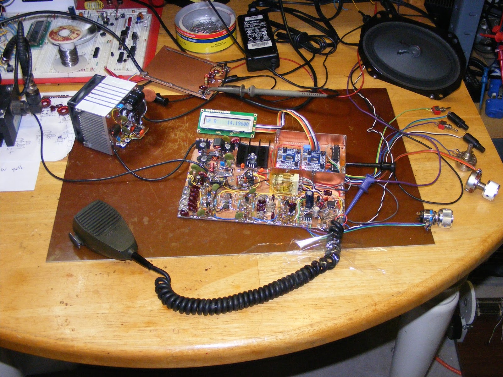
I thought I'd share my breadboard system for receiver experiments. In this example I have a phasing, single sideband Tayloe receiver. The entire receiver, less VFO, pulls 54 milliamps at 5 volts.
The chassis is a prime piece of Oregon pine. Be forwarned; my Tayloe receiver doesn't employ a single discrete transistor.
The DDS VFO at the top is the K5BCQ Si570 based RF generator kit. It reads 56.231 Mhz because the VFO operates at four times the receive frequency on a Tayloe detector.
The receiver consists of five boards. From left to right they are, RF front end filter; Tayloe detector and post detector amps; sideband eliminating phasing filter; eight pole low pass filter; high pass filter and audio amps.
Flexibility is key. Each stage, or set of stages is laid out on one circuit board which is tacked to the breadboard. Controls and jacks are mounted in scrap circuit board and screwed to the side of the breadboard.
Two parallel lengths of thin circuit board are used for the power and ground strips. Electrolytic caps are placed at each board power point. A bit of copper desoldering braid makes the connection between board ground plane and ground strip.
The circuit board is often double sided with the back side used as a ground plane. Holes are only drilled when a ground connection is needed.
Connections between boards are made using .025 diameter header pins soldered to pads. Wire wrap wire is used for connections between the header pins. These pins also make good test points. With SMT construction my intra-board signal lines rarely exceed half an inch. This eliminates coax cable for many connections.
I like to use eight pin op amps for my designs. These provide two stages and four poles in each package. I have a standard board layout. Using this single board, component selection allows low pass, high pass, band pass, gain, or no gain configurations. Multiple linked boards can be etched at one time and cut apart to meet individual circuit requirements.
Let me give credit to Dan Tayloe who developed the original receiver design in the NORCAL NC2030 CW transceiver. I also thank Pete Juliano, N6QW and Nick Kennedy, WA5BDU, for help with current design issues.
Bob--N7SUR--
Saturday, January 9, 2016
A Good Radio Morning at N2CQR

The Radio Gods were smiling upon me this morning. I started out on 17 meters and had three nice contacts with European stations: OH5CZ, a young fellow near Helsinki; HB8DQL; then RM2D in Moscow. FB.
Then Pete showed up on the Skype. As he has said on his blog, he is still struggling with a family medical emergency, but I am happy to report that he is coping well, making good use of his can-do project manager background and his good sense of humor. It was great to see him.
Inspired by my talk with Pete, with 40 meter AM playing in the background, I turned to my R2 FRANKENSTEIN phasing receiver. Last night I completed the 90 degree phase shift network. This is built around two quad op-amp chips and is designed to take the audio output from the two DC receivers and create a 90 degree phase difference between them. I tested this stage by sending the same audio into each set of op amps. I then put one scope probe in the output of one chain of op amps, and the other probe on the output on the other chain. Wow. Bingo. 90 degrees of phase shift across the 300 -- 3000 Hz audio spectrum.
Emboldened by this positive result, I put the completed stages together this morning. They passed the smoke test. Then I tuned to 40 meters. Wow again! As promised, opposite sideband rejection without resort to crystal filters. But as luck would have it, I ended up with a configuration that suppressed the Lower Sideband. For 40 meters, obviously I needed to suppress the other side of zero beat. But all I had to do to remedy this was to reach into the DDS box and switch the I and Q jumpers on the M0XPD/Kanga UK Arduino AD9850 shield. This switch put me on LSB. Very cool.
Here is a view from above:

The AD9850/Arduino DDS box is in the bottom center. Above that, near the center of the picture, is the board (from N6QW) with the two SBL-1 mixers and the initial AF amp stages. The small green board above that is the IC phase shift network. At the top of the picture you see the 3000 Hz low pass filter. Below that, the board with the little blue pot has an IC AF amplifier and a 300 HZ high pass filter.
I still have to build the audio amplifiers prescribed by the designer, Rick Campbell KK7B. But obviously I am already having a lot of fun with phasing. Here is the QST article on Rick Campbell's R2 receiver:
https://www.arrl.org/files/file/Technology/tis/info/pdf/9301032.pdf
Friday, January 8, 2016
N8NM: Thermatron Meets Silicon (Part II or III)

Bill:
Here's a pic of a Thermatron-Meets-Silicon receiver that I've been working on. Tubes are 12AT7 mixer, 2x6BA6 IF amps, 2x12AX7 (product detector, AGC amp and 1st AF) and 6AQ5 audio out. An Arduino controlled Si5351 provides the LO and BFO as well as handling all of the switching, and the mixer and product detector use variations on Dr. Pullen's dual-triode circuit. I've had this one on the air, but the hardware and software still need some, um, refinement. And painting the panel has to wait until spring as my XYL doesn't share my affinity for paint fumes.
73 - Steve
Wednesday, January 6, 2016
N6ORS's Min-X Crosses the Pond on First Contact
Very cool! Reports on new phone rigs keep coming in. It is great to see them in their "still out on the bench" condition. And reports of the first contacts are always exciting. I like the MIN-X name. This is indeed another testament to the contributions made to the radio art by our friend Farhan.
Hello Bill,
Well I just finished tweaking my new rig, I named it Min-X because I outright stole bits and piecesof the BITX and the Minima, thanks Ashhar. I made my first contact today and what a contact!
The contact was made with the rig as shown. The amp is a home brew FET push-pull.
I had a chat with Beth MW0VOW in South Wales! From Wisconsin to Wales on 15w PEP.
Oh, most of the rig was 'noodled' and constructed while enjoying you and Pete on the
Oh, most of the rig was 'noodled' and constructed while enjoying you and Pete on the
SolderSmoke podcast.
Best 73,
Keith N6ORS
Best 73,
Keith N6ORS


Monday, January 4, 2016
ZL2CTM's New Zealand Double Sideband Success

New Zealand and Australia seem to produce an amazingly high percentage of the world's double sideband transceivers. Charlie ZL2CTM adds to the count. He took inspiration and circuitry from DSB hams in both countries and produced this beautiful DSB transceiver. It is obviously -- as Charlie notes -- chock full of soul. I definitely identify with his comment about "taming some kind of electro-mechanical machine" and also, of course, with his remark about the feelings that come with putting a homebrew rig on the air. So follow the advice of Charlie! Build a DSB rig and put it on the air! Make this your ham radio resolution for 2016! Give it a go!
Hi Bill:
I have been following you and Pete Juliano for many years now, and thought I would send you a photo of my 40m homebrew rig that I finished yesterday. Hopefully, it will help encourage others to melt some solder and make their own rigs. The rig is based on ideas and designs from Eric Sears ZL2BMI, Peter Parker Vk3YE and of course Pete N6QW. The aim is to make the final version relatively compact so I can take it tramping/hiking here in New Zealand.
The VFO is an AD9850 being controlled by an Arduino Pro Mini. The output is amplified to provide sufficient drive for the balanced modulator. I was using a nice 1” OLED screen to show the frequency, but that generated a huge amount of noise, so I changed to a LCD. Changing frequency is simply a matter of moving the curser left and right then using the up and down buttons to change the number. Very quick and easy. I was contemplating a rotary encoder, but I find those always seem to skip and jump every now and then. Must be the way I use them...
The balanced modulator is a 4148 diode ring. I do have some SBL-1s lying around, but I thought I’d go with the discrete diode ring for something different. I’m using a standard electret mic and a simple single stage amp. The switch above that switches between phone and CW.
The PA is two stages; the first a 2N3053 and the second a BD139. At this stage it puts out just over 1W into a 50ohm load. I might look to add another stage and get that up to 3-5W.
The audio amp is a simple LM386. I am not running it hard out as per the datasheet as it generates quite a bit of high frequency hiss in that configuration.
Unlike Pete, I don’t have access to a milling machine to make squares to mount the components on. Instead, I use vero/strip board upside down and solder directly to the strips. This works really well for me on HF. I cut tracks with the twist of a small drill bit.
Last night I made two contacts with the rig. The farthest was 527km according to some well known mapping software. Both reports said the audio was ‘very nice’, which was great to hear. The receiver worked surprisingly well too, and I managed to hear stations in Europe.
As for user controls, you will notice that the pots, switches and plugs are all over the place. I did that to keep leads short. I like it as i feel like I am taming some kind of electro-mechanical machine to generate and receive RF.
Anyway, this little rig has a ton of soul in it and is really fun to use. There is something different about making a contact with a rig you built. I really encourage everyone to give it a go!
The next iteration will be a SDR using a Teensy. Rheslip over at Open Emitter has done some great work with that.
73s
Charlie
ZL2CTM


Sunday, January 3, 2016
TIA-Tube Hybrids from Steve N8NM (Part 1)

Last week Steve sent us a picture of his Straight Key Night rig which consisted of a homebrew thermatron transmitter and a TIA BITX as the receiver. I asked Steve for more info on the TIA BITX.
Bill:
Shot these right after making the first QSO using the TIA rig as the receiver. The Arduino and '5351 are still on a breadboard, otherwise, all of the PCB modules except the filters and PA are installed on the chassis.
The QSO was uneventful, which is a good thing!
73!
Steve

Subscribe to:
Posts (Atom)


