Just go to http://soldersmoke.com. On that archive page, just click on the blue hyperlinks and your audio player should play that episode.
http://soldersmoke.com
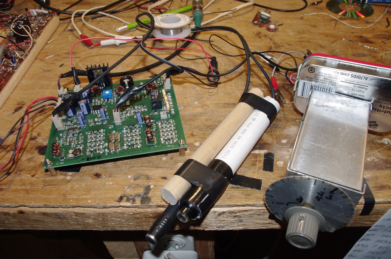
I was going to put the BITX40 Module in a box today, but I just couldn't bring myself to do it. That board looks too good to be hidden inside a box. So I put it topside. That's the analog VFO to the right. You can see a fan off to the left -- that is perhaps temporarily in lieu of a large heat sink for the final. You can see the two Gel cells in the background. I am indeed running 24 volts to the final, and am putting out about 20 watts. I had three nice contacts today on 40: WB2RON up on Long Island said I was "20 over". Later I worked W1SJ in N. Vermont -- I was 5-9. Then -- icing on the cake -- DK1NO in Stuttgart. I was 5-8. TRGHS. I kind of like this arrangement -- it has the "three dimensional" feel of an old tube rig. This obviously wouldn't be good for portable operations, but I am not planning on going portable. There is a lot of room under the chassis. I could put a digital VFO in there and put in a switch so that I can easily go from digital to analog.
I blame Pete for this. And Farhan. Pete has been leading us astray with all his talk of high power linear amplifiers ("Two 813s kid, that's all you need!"). And Farhan practically pushed us beyond QRP limits by placing a separate DC power connector for the IRF510 final amplifier on his new BITX 40 Module board. Farhan writes:
There are jump-points from where you can add more modules like the DDS, more bands, better audio amplifier, etc. Imagination is your limit. You can separately increase the power amplifier's supply voltage to 25 volts to be more than 20 watts of power : You will have to add a better heat sink. The mods are on the way!(from hfsigs.com) A while back Chris KD4PBJ sent me some very nice heat sinks -- one of those would fit quite nicely on the PA side of the BITX40 board. And I just happen to have two 12V Gel cell batteries. One will power the board and the two together will power the IRF510. With 20 watts out to my dipole I feel confident that I will WIN the upcoming ARRL Phone Sweepstakes (in my category: Homebrew VFO, Northern Virginia).
When I opened the package from India and saw Farhan's s beautiful board with all those little SMD parts, I immediately worried about frying those parts by accidentally reversing the polarity of the 12 volt DC input. Believe me, this can happen. It is especially likely during the early, enthusiastic testing and experimenting that takes place in the days after the arrival of a new rig. So, my friends: Save yourselves the agony of fried components! Don't let your BITX 40 Module go up in smoke! Install a simple reverse polarity protection circuit BEFORE you start working with your new board. Here is what I did: I just took a diode (a fairly hefty diode) and I soldered it in between the pins of that neat little circular power jack that Farhan sent with the module. Be sure to solder it in so that it does NOT conduct if you have connected the power correctly. The arrow should be pointing to positive terminal. Then put a fuse (3 amp or even a 2 amp) in the line from the connector to the power supply or battery. If you don't have a holder you can try just soldering the fuse into the line. With these two little parts, you can save yourself a lot of grief: If (WHEN!) you connect red to black and black to red, that diode will conduct like crazy and will blow the fuse. You'll just have to replace the fuse (and not the module).
This morning I built a mic/PTT for the BITX 40. I used the little electret element that Farhan sent with the rig. The element sits atop the plastic tube from a pen. For the push-to-talk I used a little push switch that locks down (on) until you push it again (which opens it). This is very convenient -- you don't wear your thumb muscles out on long "old buzzard" transmissions! I used some PVC pipe and some wooden dowel to make the thing a bit ergonomic. It is held together with Gorilla tape. It works great! I put the rig on the air this morning and very quickly worked KD3TB up in Pennsylvania -- Irwin was testing his K3. Then I worked KM4LWP -- James was only a mile or so from me, running 3 watts from a KX3. Then Mario, K2ZGW called in.Everyone said the rig sounds great.
In the picture above you see the rig, the mic and (on the right) the VFO.
That, my friends is an extreme example of what we mean when we use the word "rig."This magnificent machine sent Pete's melodious voice across the mighty Pacific several times during the recent CQ WW contest. Pete wrote to Jun:
Hi Jun,
This weekend is the CQ World Wide SSB contest and I just worked three JA stations on 40 Meters. The time 1400 UTC. I must confess that I was using 600 watts to my droopy dipole but they came back on the first call. So there are paths open and perhaps 600 watts was overkill but the timing seems like it works for a good path to the west coast. Along the way I also worked a station in Hawaii (KH6).
The rig I was using is shown below. The mainboard came from a Hallicrafters FPM 300 (late 1960) to which I added the Rx Tx Mixer (SBL-1), my stock 2N3904 bi-directional amp board, the 2N2222 + BD139 driver stage using the EMRFD circuit and a 2SC2075 final which gives about 3 watts. This in turn drives an intermediate SS amp to 100 watts and then the SB200 to 600 watts. The FPM 300 used a 9.0 MHz IF frequency.
Of course no rig today from N6QW would be complete without a Si5351 and the color TFT display. Rounding this out is an LM386 audio amp stage. Cosmetically the rig doesn’t look pretty but sure works well.
73’s
Pete N6QW
(The comments about the 813s are kind of SHOCKING, coming from a member of the QRP Hall of Fame!)
I am having a lot of fun with Farhan's new BITX 40 Module. I think I'm doing exactly what Farhan intended people to do with this rig: work on it, modify it, improve it.
I've been working on frequency stability. I was, I admit, skeptical from the start about the stability of a thumb-sized, SMD, varactor-tuned VFO with a ferrite or iron powder toroidal coil. Don't get me wrong -- it worked. But it drifted. It seems to me that it would be asking too much to expect a VFO like this to be drift-free. (But I may be wrong -- are there any SMD, varactor-tuned VFOs out there that DON'T drift?)
First I thought it might be the 9 uH metallic core toroid. So I replaced that with a 10uH choke -- no ferrite or iron powder in there. That seemed to help a bit, but SSB QSOs would still quickly drift into Donald Duck chatter. Then I thought it might be the varactor diode. I let it warm up. A lot. Still, it drifted. Then I thought it might be the trimmer cap, so I took it off the board. No change. During this process I noticed that even slight pressure on the board caused the rig to shift frequency. I began to suspect that the drift was just structural -- a consequence of the physical characteristics of the SMD parts and the board. To get VFOs stable I've had to build them big: 10 X 10pf NP0 caps to make one 100 pf cap, large air-core coils, and big sturdy variable caps. I'd isolate the frequency determining elements in a box separate from the powered components. This little VFO just looked too small to be stable.
So faced with drift, at first I asked myself, "What would Pete do?" I took an AD9850/Arduino combination off the shelf and plugged the output into the "DDS" jack Farhan had placed on the board. I removed the 10uH choke. Viola! With the DDS tuned to 4.7 - 5 MHz, the receiver worked great. I briefly tried to updated the Arduino code to take into account the 12 MHz IF (so I could get an accurate frequency readout), but ran into the old painful Arduino IDE problems: Now it is claiming there are library problems. Not wanting to suffer through another round of digi-agony, I left well-enough alone. I used the DDS with the old code for one day.
But of course, I was not satisfied. Attaching a DDS or PLL synthesizer to the BITX 40 Module just didn't seem right. Heck, it was kind of like just hooking up my FeelTech Chinese sig gen to the DDS jack. Farhan's rig is simple, beautiful and ANALOG. The parts are small, but you can see them. You can put your scope probe on the collector of Q7 and see what is going on. DDS or PLL. It is a REAL HARDWARE-DEFINED RIG. So I decided to build a VFO. Pete calls VFO's "grief machines" but for me, the grief machines are those little Arduino beasts. To each his own.
When I build a VFO, I start with the variable capacitor and the reduction drive. I found a nice one (with reduction drive) in my junk box. I tunes from 40 pf to 56 pf. I decided to use the super-simple Hartley circuit presented by Wes Hayward W7ZOI in SSDRA (page 34, fig 7).
I went with a 4.4 uH air core coil (wound on a cardboard tube from a coat hanger). Consultation with on-line resonant frequency calculators showed that I'd need to put about 180 pf in parallel with the variable cap. For this, I used a bunch (maybe 10?) of small value NP0 caps in parallel. This really helps keep the VFO stable.
As I did with my HROish receiver, I put the coil and the caps in one box, with the MPF-102 and associated parts in an attached Altoids tin. Everything was glued and bolted down very solidly.
I only built the actual oscillator stage -- I decided to use the buffer amps on Farhan's board.
The oscillator started right up. I had to add and then take away some turns on the coil to get it to run in the desired range. Then I plugged it into the DDS jack -- the receiver was working immediately.
I noticed, however, that it seemed a bit less sensitive than it had been with the AD9850 DDS. And when I grabbed the wire going into the DDS connector, audio output jumped dramatically. It took me a few minutes to figure that out: I think the output from my VFO was not adequately turning on the diodes in the diode ring. When I grabbed the wire, I was putting a lot of noise into the mixer port, probably turning the diodes more fully on (but also letting a lot of noise through).
Fixing this problem part was fun: Looking at the BITX 40 schematic, I saw that the two 1000pf feedback caps in the original oscillator were still in the circuit. I figured those caps would be sending a lot of my VFO energy to ground. So I fired up my hot air rework station and deftly removed C91, the 1000 pf cap that is connected to the base of Q9. Instantly the receiver started inhaling as it had with the DDS VFO. That was a very satisfying fix.
This whole VFO project was very satisfying. It was all done in one day, and all the parts came out of my junk box. I think I ended up with an LO frequency source that matches up in a pleasing way with the analog circuitry in Farhan's rig. And here is bonus that I think is just what Farhan had in mind: this kind of circuit adds a definite homebrew element to the module rig.
I found that this external VFO improved stability significantly. I don't know if it is as stable as the DDS, but with the external VFO the receiver no longer drifts away as I listen to SSB signals.
Finally the Mate for the Mighty Midget is finished, just in time for the G-QRP Valve Day 12-13th of November.
Got the LO fixed for 40m by lowering the parallel capacitor from 150 pF to 100 pF.
Also the 68 pF series capacitor was lowered to 33 pF for some more band spread on 40m.
It now receives from about 7.0 to 7.4 MHz and from 3.45 to 4.0 MHz
Had to exchange C1 in the end, the one used initially quit every now and then.
I only had a large 3 section variable in the junk box covering 10-550 pF, which works fine now. For the lower end of 80m I had to add additional 47 pF next to the 47 pF trimmer caps, so there it is about 600-650 pF max!
At the high end of 40, it is also just not too much.
The meter was used as a position indicator for C1.
Tried several ideas, but with no separate tube for AGC, I couldn’t get it to work as a S- meter
Read something about audio derived AGC, maybe this is worth a try.
The BFO can be switched off for AM reception.
Simultaneously the input on the mixer side of the crystals is disconnected but still coupled by some capacitance of the switch wires.
AM reception is possible, but not very good.
Need to find a better solution which doesn’t degrade the crystal filter properties to much.
(By the way, the detector regen. control ads about 4 dB to the AM sensitivity)
The receiver will mainly be used for CW/SSB reception, so maybe it stays this way for a while J
I hooked it up to the W1TS transmitter, which was very loud.
Didn’t foresee a T/R relay (learned a lot from this project ;-) ), so added this one between the front plates next to the RF and audio gain control.
The quit down everything a little, the RF gain pot is lifted of ground as suggested by James, N2EY at QRZ.com.
It helped a lot, but was still too loud if tuned exactly in the bandpass of the crystals.
The T/R relay now also switches an adjustable potentiometer at the input of the audio pre-amplifier.
The dial cord has no lag, and works very well for fine tuning.
Unfortunately the reduction drive went from 1:19 to 1:9…, the tuning capacitor only has a 180 deg. span.
Something to remember for the next receiver.
It’s a nice little receiver and quite stable after warm-up.
The only extra luxury a next receiver will have, is AGC.
But with no AGC it’s easier to tune the antenna tuner by ear J
There’s now a complete homebrew station here, antenna, feeder, tuner, receiver, transmitter, power supply, al home made J
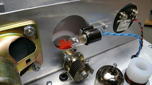
About the Mystery Hole….
If you haven’t guessed it by now, or Pete hasn’t told you, it is revealed in one of the pictures below.
So many great Double Sideband projects come from Down Under. There are the various versions of the famed ZL2BMI rig. And Peter Parker VK3YE has long been the acknowledged guru of DSB. In fact, Peter sent me an enthusiastic e-mail about the new ZL DSB rig pictured above -- his e-mail arrived before the message (below) from the intrepid builder. I detect a bit of the "Tucker Tin" influence in this rig. (But perhaps this one is more Tupper than Tucker!) Charlie's work has graced out blog posts before: http://soldersmoke.blogspot.com/search?q=zl2ctm
You asked recently on the podcast for listeners to let you know what they had on their work bench. Well I’ve been working on a tramping (hiking) radio, which is now complete. It’s a DSB 5W rig designed for 80, 40 and 20m, as well as our New Zealand mountain safety radio system. I designed everything in LTSpice as was suggested by Pete, N6QW. That was great, as I could ‘desolder’ components with the mouse and instantly see what impact it had on the output. An amazing tool that’s free! I highly recommend it.
Once again I’ve used upside down strip board for each stage, which are tacked down onto an un-etched copper board (earth plane). That seems to work really well for me.
The rig uses an Arduino mini driving a small OLED screen and a Si5351 DDS. The Si5351 is going straight into a SBL-1, which seems to work fine too. The AF strip is a 2N3904 before a LM386, which has enough drive to run a speaker. The TX amplifier is a three stage one with shielding between each stage. It’s made up of two 2N2222A stages followed by a BD139. That in turn is followed by three simple filters, one each for 80, 40 and 20m.
The next project will be a proper SSB rig using a crystal filter salvaged from an old Codan 7727. Like this one, it will use an Arduino and a Si5351.
Finally, I am certainly no expert in homebrew, but I hope my ‘dabbling’ will help inspire others to pick up the soldering iron and give it a go. If I can do it, then anybody can! There is certainly a great sense of achievement to operate a rig you built yourself.
Regards, and thanks to you and Pete for all your inspiration.
"SolderSmoke -- Global Adventures in Wireless Electronics" is now available as an e-book for Amazon's Kindle.
Here's the site:
http://www.amazon.com/dp/B004V9FIVW
Wireless sound mixing
-
I don't go out to see bands very much but recently we attended a dinner and
show by The Martini Set. It was an enjoyable evening but what caught my eye
was...
April 27, 2024. Tubes or Transistors?
-
A recent acquaintance and newfound friend suggested I cover the tube versus
transistor dilemma. Some Blog readers may even be saying why are you
wasting my...
Power standing wave null… solution
-
Power standing wave null… more left readers with “homework” to create the
Pfwd and Prev traces. Remember that Pfwd and Prev are interpretations in
the cont...
Did you know there’s a new MTR-3B in the works–?
-
A reader reached out to me this morning asking about the Mountain Topper
MTR-3B. It reminded me of a teaser LnR Precision posted earlier this month
in an M...
We’re a garage band, we come from garageland
-
Hi, FastRadioBurst 23 here letting you know of a couple of our shows this
week. On Sunday 28th April 2024 at 0900/1300 hrs UTC on 6160 kHz and then
at 2000...
An Inline RF Step Attenuator for QRPp Work
-
I don’t need to explain the attraction of low power operation; if you’re
reading this, the chances are that you are already a convert. I’ve been
operating ...
Using an external clock with the RX-888 (Mk2)
-
*The RX-888 (Mk2) and external clocking*
*Figure 1:*
The RX-888 with external clock input *(right)*
The enable/disable switch is barely
visible behind the...
A 51S-1 Restoration Story
-
I came across my Collins 51S-1 in a big junkyard in Ankara, Turkey around
2012. It was in a pile with a lot of other electronic scrap, probably from
one o...
New QRP Cluster Online From OM0ET and OM6APN
-
By DX EXPLORER
DX EXPLORER
Paul OM0ET and Peter OM6APN recently launched a new cluster dedicated to
QRP operations. Have a look and I hope you will enjoy...
3D Printing The Hadley 114mm Newtonian Telescope
-
Yes, we’re building a 3D Printed Newtonian Telescope called Hadley. It’s
being printed in PETG and in the video below, I give a quick tour. My build
isn’...
3D printed project boxes
-
I have been busy with some other things that have kept me away from
electronics projects for quite a while. Now I can get back to them, but
realize I n...
Daylight Again – An all Analog Radio
-
What’s all this? In 10 seconds, A high performance, 7MHz, 5 watt SSB rig
Draws just 24 mA of current 90 dB dynamic range, 80 dB close-in dynamic
range 3D ...
Adding Enclosure to your sBitx Boards Order
-
The early buyers of the sBitx board set who bought it for $270 USD might
want to also add the enclosure (box) for in the kit. What you will now get
is a f...
Digi-chirp! Digital synthesis of ‘nostalgic’ CW
-
The bottom ends of 80, 40 and 20m are not what they used to be. For
starters, the busiest part is the digital segment where computers talk to
computers – l...
-
A Simple Speech Processor
(For QRP/SSB Homebrew Transceivers )
Over the last few weeks I had been thinking to build a small AF speech
processor to add to...
A New Look for your uBitx!
-
Adding a "Cool Blue" Display to your uBitx!
The standard "green background" with black lettering frequently reminds me
that I suffer from Chronic seasickn...