Podcasting since 2005! Listen to Latest SolderSmoke

Saturday, March 18, 2017

Channelized! BITX 60 with the Five Channels (with video)


Here's an update on my BITX 60 project.  The modified module is in the lower box.  An Arduino Uno and an Si5351 (this one with unreleased smoke) is in the Heath QF-1 box on the top.  I am using an Arduino sketch written by Don ND6T. It spits out the needed 17 MHz LO freq needed for each of the five 60 meter channels. You can scroll through the channels by just holding down the rotary switch interrupt button.

There is a move afoot to liberate from channelization about 15 kHz of the 60 meter band. When that happens, I'm ready to go -- I'll just reconnect the rotary encoder for the Si5351 and load some new code.  I suspect that by the time that happens, Don will have modified his code so that the 15kHz "tunable" segment will be integrated into the current program and will appear as one of the options as you scroll through the choices. 

For reasons that most readers will understand, I have resisted channelization for many years.  But here I am, channelized on 60.  It is not so bad.  I'm having fun listening to a new band, using a modified BITX, an Arduino, a bit of Heathkit and code from a fellow ham.   


Thursday, March 16, 2017

BITX 60 (with three short videos)

Inspired by Don ND6T, I decided to put a BITX40 Module on the 60 Meter band.  All you really have to do is modify the bandpass filter.  Don showed us how to do this by simply adding three 100pf caps.  I was going to order SMD caps, but this just didn't seem right -- I found three of the old "with wires" kind and easily soldered them into position.  The bandpass shifted as Don had promised.

You also have to change the VFO freq.  You need it to be in the 17.3 MHz range. Don has a nifty program for the Raduino that also works with the Si5351/Ardunio Uno combo that I use.  It keeps you on the five channels currently authorized on 60. Unfortunately I managed to let the smoke out of yet another innocent Si5351 breakout board.  Amazon and Lady Ada are sending me another one, but in the meantime I pressed into service an old AD9850 DDS. I had a little trouble getting the 17MHz signal through the BITX's VFO 4 MHz VFO system, but I eventually figured it out. (More on this later.)  

The receiver is working nicely.  I like the relaxed 60 meter conversations. 


Tuesday, March 14, 2017

For Pi Day (3.14) - Looking Back on 5 years of Raspberry Pi Tinkering


Not by me, thank God! No, the five years of Rasp Pi maso-tinkering were done by Thorin Klowsowski.  His report appears here:

http://lifehacker.com/what-i-ve-learned-from-tinkering-with-the-raspberry-pi-1793236686

In the second and third paragraph, he confirmed all my suspicions:

The Raspberry Pi is far, far away from being as user friendly as a PC or Mac. That’s a feature, not a bug... Before hobbyists latched onto the Raspberry Pi, it was a computer for learning how to code targeted mainly at kids. Since then, the appeal has broadened, but it’s still impossible for a project to “just work” out of the box. You will have to tweak something, dig into the command line, or spend a few hours buried in an obscure internet forum to find solutions to problems that only you seem to be having. You will slam your head against the wall, yell a little, and throw your Raspberry Pi at least once for every project you attempt to make.

I told you so. 


Sunday, March 12, 2017

KC1FSZ's Peppermint Bark BITX: Aeronautical Mobile for his FIRST QSO. TRGHS.


Bill and Pete:

Can’t say enough good things about your podcast - thanks for all that you do.  I’m a fairly new ham and have been trying to go the home-brew route as much as possible.  

I bought a BITX40 module (pre Raduino vintage) and added my own VFO board using the usual parts.  Actually, I’m using a Teensy 3.2 instead of an Arduino because it is a faster part and has a lot of DSP functions built into it that I’m using for digital mode stuff.   But it’s the same basic idea.  

My BITX40 is not as photogenic as some of the others, but I sent a picture below. This is the “biscuit tin” variety.  It’s was funny actually: a co-worker of mine stopped by my office around Christmas to give me a gift and pulled out of his bag a very nice box of “peppermint bark” candies with a ribbon around it.  The VERY FIRST thing that crossed my mind the instant I saw the gift was …. BITX40 ENCLOSURE!  He must have been pleased to see the huge smile that came across my face. :-)   I’ve been bitten by the bug for sure.  

My first three HF QSOs (ever) where on the BITX and were all very interesting:

  • First real QSO of my life was with KE4TJB “air-born mobile” off Delaware.  He is a commercial pilot flying for JetBlue and apparently has time to work QRP stations during flights??  I wonder who was flying the plane?
  • Then I was scanning around this morning and caught K4HW making last calls for check-ins on a net running on 7242 out of North Carolina.  I decided to give it a shot, having never joined an HF net and I was recognized!  As the first round got going I realized I had joined a Jehovah’s Witnesses net.  They were very friendly and the net control stopped to help my get my frequency calibrated before they continued with the scripture passage for the week.
  • Later this morning I reached K3KLC in Maryland who had the high-end SDR rig with the waterfall/panadaptor/etc.  Remembering comments that you guys have made about these types of folks on 40m, I was very concerned.  But this guy turned out to be very helpful and sent me some screen shots showing what my signal looks like.  

Thanks again, and 73s,
Bruce MacKinnon
KC1FSZ
Wellesley, MA


Saturday, March 11, 2017

WA8WDQ Builds OZ1JHM's Arduino CW Decoder (Video)


Bill, Pete:
I wanted to update you on my DC receiver progress.  While I'm still operationally proficient in CW, many of my friends are not.  So I thought it would be fun to add a CW decoder to my DC receiver. 

In my research for a solution, I ran across a sweet decoder I thought might be of interest to the SolderSmoke listeners.  OZ1JHM developed a totally software based decoder for Arduino that uses the Goertzel Algorithm.  This algorithm performs similarly to a Fast Fourier Transform but only for tone decoding at specific frequencies.  This limitation keeps the code small and fast making it perfect for microcontrollers like the Arduino. 

I was able to hack Hjalmar's code into mine and the result is CW decoder functionality in the receiver with no additional hardware!  But, the Arduino Uno's performance is limited so I need to dynamically switch between receiver VFO/control code and the CW decoder in order to preserve real-time performance.  This is only my first pass so perhaps I will find a way to optimize the code to more fully integrate the two.  I currently switch back and forth based on whether the VFO knob has been rotated or is idle.  This at least gives the illusion of real-time integration but makes it harder to tune in a signal for the decoder. 

Now that the Arduino Zero is available, I've been considering moving that direction to dramatically improve available horsepower.  This isn't the first time I've run out of gas with the Uno.  Now it's time to start working on a transmitter module for the radio :).  You know, even though I have an operational K3, I find myself reaching for this radio first.  Something magical about using something you've created :).  But hey, preaching to the choir!

Be sure to check out Hjalmar's site (http://www.skovholm.com   and 
http://skovholm.com/cwdecoder) for details on his design and a video demo.

Brad  WA8WDQ

Wednesday, March 8, 2017

WU2D's Wonderful Video on Retro-QRP


(Link to video appears below.)

Stephen G7VFY sent me the link to Mike WU2D's Retro-QRP video.  In the last month spoken to Mike at least twice on 40 and 75 meter AM.  Stephen was responding to a post I did about a 1958 18 milliwatt solid state QRP rig.

Mike's video is really wonderful.  I've never been into military surplus, but this video made me think I might want an ARC-5. The rig Mike builds and tests is very similar to our beloved Michigan Mighty Mite. His description of the build and the testing procedures he used will be of great interest to those who've built the MMM rigs.  And he made some contacts.  Finally, there is a cameo appearance by Paris Hilton.  And she is holding a HOT transistor!  Wow!  

Mike has a real talent for making these kinds of videos. Thanks a lot Mike -- see you on 40.  And thanks Stephen (Stephen has sent us so much great stuff over the years, including a fantastic box of British valves.)   Pete:  See how nice it is to get back to QRP?

Here's Mike's YouTube Channel. I love the intro:
https://www.youtube.com/channel/UCN7RQv_qmzhzuJV1HhJ4OEA

Tuesday, March 7, 2017

Beyond Al Fresco: Boxed Up In Style with AB1YK's Very Cool BITX Box


Mike AB1YK is doing some excellent work boxing up the BITX. 
Check out his article on the Nashua Area Radio Club Blog:
http://n1fd.org/2017/02/28/my-ssb-bitx-40-build-from-vu2ese/

Here is a picture of Mike's case:

These enclosures might become available for purchase soon...

Saturday, March 4, 2017

SolderSmoke Podcast 194 - Approaching the Digital-Analog Singularity


SolderSmoke 194 is available (scroll down for link)
March 4, 2017
BIG NEWS:   uBITX from Farhan
BENCH REPORTS
Pete: Recycling Old Boards
Working on Arduinos and advanced displays
Bill: SDR Adventures and Misadventures.
RTL-SDR is fun.  Built HB front end.  
HDSDR under Windows is fun and easy.
Thought about Raspi3, 7 inch touch screen, Linux, software YUCK.  
Followed advice of Ken G4IIB and got a 50 buck tablet with Google Play. 
Who needs tiny OLEDs?  Use a 7 inch tablet as your display!
Building a Ceramic Resonator for the HRO  455 kc filter
The value of doing something different. 
Boxed up my NE602 OLED rig. 
OLED noise and ACTIVE decoupling.
NE602 and MOSFET tips
LEXICON:  
OTD   Obsessive Tinkering Disorder  G6LBQ
"A Thing of Beauty"  
Source of Tombstoning term:  Don ND6T.
Ken G4IIB’s extremely smooth audio.
ON THE AIR:
On AM on 75 and 40.  Fun.  Old Military Radio Net and "The Lonely Guy Net" on 75 Saturday morning.
Good old 17 meters. Open at mid-day
HB2HB on 40 with W0PWE.
Listening on 60
Hambrew magazines disappeared, but are back now.
EMRFD Classic Edition available
New Posts to BITX HACKS
MAILBAG:
Gloves follow-up. Not a good idea.
VK3YE’s QRP by the Bay event  and a new book!
Colin M1BUU achieves Mountaingoat status
Martin A65DC JoO MMM in the UAE
Tom NY2RF Editorial with mention of JoO!
Lots of Al Fresco rigs: W8LM BITX on a board, Brad WA8WDQ DC RX, KA4KXX Al Fresco OZ DSB
ON6UU DSB from Spain via Belguim
Hugh ZL1UEM SMALL Si5351 OLED
Cookie Tin rigs VK2EMU’s Biscuit Tin DC RX,  WA7HRG’s Popcorn rig
VK4FFAB FB LTSPICE intro
Ken G4IIB’s BITX adventure (with VERY smooth audio.  How smooth? We can’t say.)
VU2XE’s BITX with a CAD box
G0ETP’s shockingly beautiful SDR receiver
Alan W2AEW on the mend with broken ankle.  His videos are a treasure trove of tribal knowledge.

Friday, March 3, 2017

Farhan's NEW uBITX Multiband Transceiver (video)


It is, truly, a thing of beauty.

Farhan will be posting details on his web site soon. 

Thursday, March 2, 2017

Jim WA7HRG's Beautiful Popcorn BITX

From the earliest BITX articles, Farhan has encouraged the use of discarded  cookie or candy boxes.  Jim's popcorn box is clearly in this tradition. There is also, of course, a connection to the idea of using simple "popcorn" transistors.
Popcorn Radio
by Jim Purvis WA7HRG

While celebrating Christmas and a Birthday at Disneyland in Dec., my wife and I enjoyed a box of popcorn during one of the many parades.  It was too nice a box to toss in the trash so I brought it home.  It kicked around the QTH a few weeks until I caught the BitX40 v.3 fever.  Wow, just enough room for the BitX and a few hacks, and the project was on. And a very neat way to remember our good time at Disneyland.

I decided on several hacks and mods and made a list.  In the end I settled for less. Hihi
1.       Switchable 5 or 20 watts out.
2.       Single power supply.  24 volt PA with a 13 volt regulator for the rest of the radio.
3.       Dual band. 40 and 20 meters.
4.       SSB and digital mode operation.  Built in audio interface and sound card.
5.       A tune function for antenna adjustments.
6.       On screen S-Meter.
7.       2.2” color TFT display.  Because I can display more information and it’s just cool. The Radino it came with was set aside for another project.

I had a 24V  5amp laptop power supply as the base supply.  I used two 7812 regulators in parallel and an aluminum plate heatsink and raised the common a little above ground for a 13 volt output.  I could then switch that between 24V for the PA.  Regulators get a bit warm when using them in the 5 watt position so most operation will be at 20 watts.

Dual band operation was soon abandoned simply do to space limitations in the box.  I had no room for additional BPF and LPF.

The audio interface not only provides ground isolation and level control between the PC and the radio it also provides a VOX operation for digital modes.  The digi software can provide the PSK (or other modes) audio on the left audio channel and a continuous tone on the right.  I use this for the VOX operation.  A ‘thumb drive’ size USB sound card provides the connection to the PC with just one cable.

Antenna tune function was provided by a version of Pete’s LBS method and I just used a small relay and a push button to activate PTT and to unbalance the balanced modulator.

The S-Meter proved problematic for me.  I might not have had it if not for help and advice from Pete.  It may not be accurate but provides a good relative signal strength indication.  And looks very cool!

The DDS is a quagmire of several different sketches and some of my own coding.  This was my first adventure into actually coding the sketch from (almost) scratch.  I am sure I am very close to the maximum times you can program an Arduino as my “Guess and Test” method of coding became very arduous. All switching of mode, power and other functions are done at DC allowing me to use that as inputs on the NANO to change DDS function and displays.

All and all I am very pleased with the way it turned out.  Not sure what I’ll do about losing 20 meters.  Hmmm guess I’ll just have to build another radio.  J


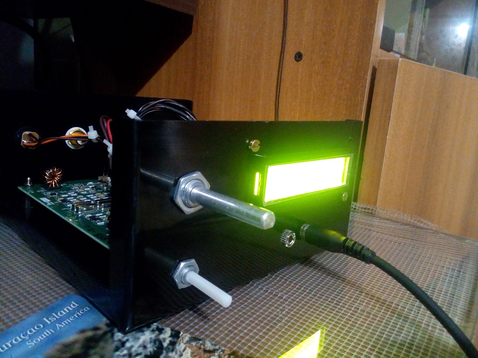
Front cover.  Upper Right corner is the Digi/SSB switch.  Tuning and vol are at the bottom. All controls and switches were located, sometimes in odd places, to retain the graphics of the box.https://ssl.gstatic.com/ui/v1/icons/mail/images/cleardot.gif

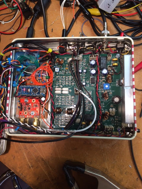
In the lid.  Upper left corner is the digi/SSB switch and across the top is the audio interface ckts.  TFT is in the middle Right.  Below that is the 3.3v level shifter and encoder.  On the heat sink are two 7812 regulators in parallel.  I raised the common a little above ground for 13v out. Far left is the vol control and S-Meter amp and det ckt.

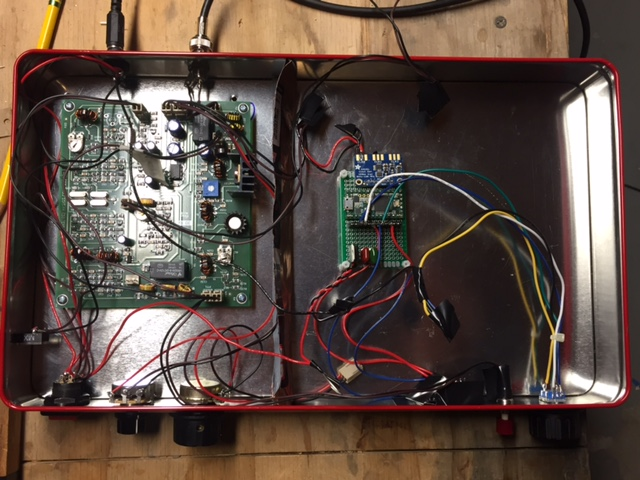
The main chassis. Across the back left to right are power input, spk jack, mic/PTT jack, ant connector, and 5/20 watt switch. Far right is the PA heat sink. A 1x.5x4" aluminum bar.  It's what I had... Lower right corner is the tune push button and if you look close in the upper left corner of the main board is a mini relay glued to the board near the bal modulator. That unbalances the modulator and provides a carrier for antenna tuning. Upper left of the box below the power connector is the USB Sound Card for the PC interface. And a couple extra input wires I ended up not using.  Below that is the standard Nano and si5351.

Last but not least is the 2.2" TFT.  All functions power, mode, etc., are DC switched.  I also use that as inputs to the Nano for display changes. I sense the 12 v relay voltages and through a voltage divider to input pins.
It has been a fun project and I can continue to play with it, but I think its time to button it up and use it a little.
 It's back to my General Coverage Rec that I started but never finished.

 73  Jim WA7HRG

Wednesday, March 1, 2017

"CQ Transistor" -- The 1958 Mighty Milliwatt


I think it is time that we get back to our QRP roots.  Perhaps under the influence of the wizard of Newbury Park (N6QW), we've all been drifting into the world of high power.  It starts innocently:  you hook up a second gel cell to the IRF-510 and suddenly you are at 20 watts out from the BITX.   Before you know it, you have an uncontrollable urge for 3-500Z's.   Here is a story that will get us back on the QRP track:

It was September 1958.   On the 14th of that month I began my first orbit of the Sun.  Band conditions were VERY good.  OM Don Stoner was on 10 meters with a homebrew solid-state milliwatt rig calling CQ TR, CQ TR (CQ Transistor).  Jarno PA3DMI in Amsterdam sent me the link to a Radio News article by Don Stoner.   The article (and the entire magazine) is a lot of fun.  Check it out.  The QRP fun begins on page  51.    Thanks Jarno!  
http://www.americanradiohistory.com/Archive-Radio-News/50s/Radio-News-1958-09-R.pdf

Monday, February 27, 2017

VE7SL and THE POWER OF THE GREEN GLOW

Steve VE7SL recently discussed Heathkit's wise use of the color green in the VF-1 and DX-100 frequency readouts.   The power of green is visible in the above photo of the N2CQR AM station. (I used this gear to check into the Old Military Radio Net and the Lonely Guys' Net on 75 meters on Saturday).  Note the VF-1 on the shelf in the upper left, and the awesome green oscilloscope trace.  Juliano Blue is all well and good, but let's not deny THE POWER OF GREEN.

Steve's discussion (and cool Knack story):  

http://ve7sl.blogspot.com/2017/01/the-green-glow.html

Sunday, February 26, 2017

CONFIRMED: Andy G6LBQ Has The Knack (and OTD)


The early fascination with small light bulbs, switches, and batteries confirms the diagnosis. The Ladybird group seems to have led many a young British person down the path to OTD (see the web site for more info on this malady).

https://g6lbq.blogspot.com/

Andy writes:

Hi Bill
 
I have built a few BitX transceivers and developed a 9 band version which has been built by various hams around the world.
 
Always look forward to the SolderSmoke podcast which I enjoy immensely.
 
For your interest I have attached some pictures to show you some of the modules I have designed/developed and built for my Multi-Band projects. The SMD boards are for my latest project which I call the Irwell Transceiver, my intention is to make it all band HF and multimode.
 
Hopefully my pictures will meet with the SolderSmoke approval and the inauguration can take place for recognition that I officially have The Knack, failing this it will be a Basta moment at the G6LBQ workshop!
 
Keep up the great work you do with SolderSmoke which brings pleasure, fun and inspiration to hams all over the world.
 
Kind Regards
 
Andy de G6LBQ


Saturday, February 25, 2017

G0ETP's Amazingly Beautiful SDR Rig


This is almost too much for an HDR guy to take. Really impressive. 

Check out his QRZ.com page:

https://qrz.com/db/G0ETP/?mlab= 


Friday, February 24, 2017

More DSB, from Belgium and Spain

Frank ON6UU writes:

Hello Soldermelters,
 
Maybe some interesting news for you as there are some new kits at hand from EA3GCY (http://www.ea3gcy.com)
 
I’ve made the MFT-40 DSB without any problem,  all parts were provided with the kit,  only things to buy were a microphone connector,  a speaker and an antenna plug.   The box was taken from my attic and was a VGA-selector in his previous life.
Kit came together in a few evenings,  I followed the very well written manual,  all was well pointed out,  which resulted in a working kit.  After aligning the kit I could start making qso’s.   The microphone was made from a piece of tube,  a simple switch and a electret microphone,  it doesn’t look pretty but the microphone works.
 
Rx-Tx 7.066 – 7.133  (With DDS the complete 7MHz band)
Pwr :  some 3W peak.
Double Side Band
 
Made some You-tube films about it.  
 
Easy to make,  no SMD,  easy alignment without necessity of expensive material.   Fine for someone who never made a transceiver,  hence the name...My First Transceiver,  MFT.   As soon as the weather permits I will take the TRX out in the field and activate a SOTA with it.
 
Now working on the MFT-20 DSB.   I’m hoping for an 80mtr version to come available too.  :-)
 
All info is on Javier’s site. (http://www.ea3gcy.com)
 
72, 73
Keep the solder melting !!
 
ON6UU


Thursday, February 23, 2017

Walter KA4KXX's "Al Fresco" Oz DSB rig with VFO Mod


A while back we ran a post about the MDT 40 DSB rig out of Australia. Walter KA4KXX liked the design so much that he built his own version and, with it, made his first homebrew phone contacts. I always say that DSB is a great way to break into the world of microphones.  Walter is obviously on the right path -- not only did he come up with a nice Al Fresco DSB rig, but he modified the VFO to get additional coverage and to incorporate a frequency counter.  FB Walter!

Walter KA4KXX writes:

Since I earned my Ham Radio license in about 1979, I have always operated only on CW since I like to build all my own equipment, but recently at the SolderSmoke website I discovered the MDT 40 Meter DSB Transceiver, and decided this was the design I had always been looking for to finally build and operate on phone.

After I made my first phone contact after only 5 minutes of trying, just a few weeks ago, I was so excited I sent an email thanking designer Leon of ozqrp.com.

Then I modified the VFO further to cover the entire 40 meter USA General Class License phone band, which is 7.175 – 7.300, in two overlapping steps.  I also added a 5K fine frequency adjustment, used a more friendly 1SV149 Varactor diode which I purchased on EBay at very low cost, and also added a high impedance buffer (found at the website listed below) to the VFO to drive a frequency counter.
 
http://www.arising.com.au/people/Holland/Ralph/buffer/highimpedanceprobe.htm


I was able to implement these modifications very easily since I always make my own un-crowded state-by-stage Manhattan style circuit boards and build first on a breadboard.
So far I am very pleased with the results.


Walter KA4KXX

Tuesday, February 21, 2017

HB2HB: Contact on 40 meters with W0PWE


I got on 40SSB this evening and called CQ with my BITX DIGI-Tia.  Hooray!  Jerry W0PWE answered me with HIS 40 Meter DIGI-TIA.  His is still Al Fresco style.  Very nice.  We add this to the homebrew to homebrew scorecard.  Thanks Jerry!

Jerry's rig:


Monday, February 20, 2017

VU2XE's BITX40 (with a cool CAD box)

A year or so ago Pete and I encouraged Kiran VU2XE to try the BITX.  He followed through, on our suggestion and went a step further, using CAD to design a box for the BITX.  I will try to post a link to Kiran's CAD files on the BITXHACKS blog.  

Kiran writes:

Hi Bill and Pete,
It is almost year since you seeded idea about the BITX. I am still a listener of your podcast.
After finishing my RF amplifier project late last year, I was thinking of few projects and BITX was on the top of the list. I ordered and received a very beautiful BITX40 kit with Arduino, I got it recently. I also designed a simple case for it using CAD software. It can be used by anyone -- just go to your local laser/CNC shop to get it cut in Aluminum.  I just thought of sharing the excitement with you.  This rig and it sounds awesomely good :)

Attached are some snaps and design files (I am no expert in CAD etc. it is my first attempt to learn and build)

Happy projects and 73s
Kiran VU2XE 


Saturday, February 18, 2017

Peter Parker VK3YE on Vintage Gear (in his new book!)

Homebrew Hero Peter Parker has a new book on the market.   I was really taken by his description of the joys of restoring older gear.  Peter really nails it.   Here is an excerpt:

Vintage Equipment
     The collection, restoration and use of historical equipment is another movement in amateur radio.  The musty smell of warming dust, the heavy clunk of rotary switches and the velvet smoothness of precision tuning drives are joys of every use.
     Such sensuality is absent from modern plastic-fronted, wobbly-knobbed transceivers.  Old rig cabinets felt they had something in them.  A kick would hurt you more than them.  And etched panel markings confirmed they were built to last.
    Unlike today’s dainty push buttons with stunted travel and disembodied beep, toggle switches showed you where they stood.  Weight, life and play made adjusting controls for nulls and peaks (as often required) both a pleasure and occasional frustration.  Even if only as mechanical backlash on a bad tuning dial, it was as if the equipment was telling you something, like a ridden horse does through its reins.  Not like newer gear’s lack of tactility which is like a ‘dead fish’ handshake, all take and no give.
    There are psychic as well as physical joys.  The thrill of bringing neglected or dead equipment to life drives many.  It’s an underestimated skill.  You start with nothing and almost anything done represents progress when building from scratch.  Whereas with a repair it is very easy to render something that’s 80% good completely useless with a careless drop or slip.

More about ‘Getting back into Amateur Radio’ is at
http://home.alphalink.com.au/~parkerp/gettingback.htm 
& the video at https://www.youtube.com/watch?v=g4ktP5K4x-I

Friday, February 17, 2017

Back from the Raspberry Pi SDR Brink

Earlier this week I shocked Pete Juliano by telling him that I was taking a break from my normal analog, discrete component, no-chips mode of construction so that I could put together a Raspberry Pi-based SDR receiver.  Even from 3000 miles away, his astonishment was clearly perceptible. He seemed briefly disoriented by it.  I'm sure some of you may have a similar reaction.  

I'd been lured in by that video of the Raspberry Pi RTL-SDR receiver with the very cool  touch screen display.  It has a waterfall!  And a touch screen! How could I resist?

I went to Amazon, but there I discovered that that attractive display is not exactly cheap. And maybe I'd need a new Raspberry Pi.  At this point, in search of economy and convenience, I began rummaging through my digital junk box.  There I found a Rasp Pi Model B.  And an old computer monitor.  This will be easy, I thought.  Just get some SDR code into that Pi, hook up the RTL-SDR dongle and Bob's my uncle, right? 

Not so fast.  I quickly began to run into daunting digital obstacles. Sure, the Raspberry Pi fired right up and filled the computer display with lines of code.  But it was all Linux.  Yuck.  Sorry Linux fans, but for some of us mere mortals,  Linux is a weird opaque world in which every little thing is somehow a lot harder.

I also began to suspect that my 2013 Model B might be sort of a Model T in the Rasp Pi world.  It might not be up to the computing task.

And finally, as I poked around the internet, I began to conclude that the Raspberry Pi software for SDR is not quite done yet.  All the sites seemed to have the word "experimental" in there.  And lots of "I'm pulling my hair out" comments Maybe I'm wrong, but maybe we just need to give this more time.

Let me ask the distinguished group some questions:

Is my Model B really useless for SDR purposes, even if I don't need all the bells and whistles?

Is there an SDR program that can be easily placed in a Raspberry Pi by someone who has NOT mastered the mysteries of Linux? 

For now, I have cleared the raspberries from the bench and am back to working on HDR stuff. 

New Posts to BITX HACKS

Don't miss the new posts on the BITX HACKS blog.  There are some great ideas from Don ND6T and some wonderful tribal knowledge from Pete N6QW.

http://bitxhacks.blogspot.com/

Sunday, February 12, 2017

Ken G4IIB's BITX Journey


The work of Ken G4IIB has been on this blog before -- he helped many of us make use of the amazing RTL-SDR Dongle SDR receivers.  He has recently turned his attention to the BITX40 Module and offers some great ideas for testing and for modification.  Ken's description of the smoothness of his audio adds a very evocative term to the SolderSmoke Enhanced SSB lexicon.     

Hi Bill, Pete

Many thanks for your respective responses to my plea for help in setting up SI5351 derived BFO to my BITX40 board. You were both on the money.


Pete suggested that I had too much gain in my HB amplifier from the SI5351 output to the modulator and indeed that proved to be true. Once sorted I also noted that I was getting extra hiss on switching to one of the sidebands as you pointed out Bill this proved to be due to incorrect placement of that particular BFO frequency.

These BITX40 boards that Ash Farhan has developed and released to the world wide community of Radio Amateurs are worth every penny. Because they are so hackable (not just the circuitry but now the Raduino code also) it means that you can tailor it to your specific specification and in the process you are likely to learn new stuff and make new friends. I describe my BITX40 incarnation and experiences below:

Upon first firing up the BITX I was getting quite a lot of mains hum from my PSU's (I thought that at least one of these PSU's was a quality item) but obviously not up to the job. I constructed a simple one transistor capacitor multiplier (this converted a humble 1000uF cap into a 1F cap) and the noise magically disappeared. By coincidence I note that Bill discussed this technique in a recent pod cast. Another advantage of this technique was that I got a 2V drop across the transistor so by running this on 13.8V I get 12V out so I run the PA section on un-smoothed 13.8V (this gives me 12 watts of RF out) and run the receiver section on the smoothed 12V output from the multiplier, happy days.

My thoughts were to turn my BITX into a multi band (several bands rather than all bands) rig and I figured that using high side mixing (running the VFO at 19Mhz (12Mhz + 7 Mhz) rather than the existing low side mixing (12Mhz - 7Mhz=5Mhz VFO)) would be a better option. For example running it on 17M would mean using high side VFO anyway. I also wanted the ability to be able to switch sidebands especially on the lower frequencies so that I could use the rig for Digital modes in my case this was to be achieved by coding the Arduino to run a BFO on one of the SI5351's clk ports.

I bought my BITX prior to the release of the Raduino so I had already commenced (with the aid of a new found radio friend and RF mentor) coding an Arduino VFO/BFO using a UNO and SI5351. Like I said at the beginning once you let folk know that you are starting on a new and interesting project you start to engage the more practical members of the ham community and they just want to get involved and help. Yet another good reason to buy a BITX . We used code originally developed by Jason Mildrum NT7S and Przemek Sadowski SQ9NJE and tailored it to suit the BITX40 and our requirements. This include high side VFO with frequency step adjustment and a BFO with long push BFO changeover. This meant that my BITX front panel should stay very minimalistic 2 knobs.
Getting the VFO to work was simple as the DDS socket was used and to better accommodate the high side VFO I modified the board by tombstoning caps C91 & C92.

Getting the BFO to work proved to be more problematic I was troubled with hiss and other noise. Words of wisdom from Pete Juliano when asked if I was doing something wrong were: " No –it is just that we tend to think our projects are like Lego type building blocks where everything mates and snaps together. Sometimes more is required". True Pete and that gives us the opportunity to learn new stuff!

To cut a long story short I found that the best place to connect the BFO was on the modulation transformer T4 thus bypassing the BITX BFO stage altogether. I was also getting hash noise believed to be emanating from the Uno. At this stage my after market Raduino arrived from India. I fired this up and noticed that I was not getting any hash noise from it. This pointed us to a coding problem and the LCD refresh was altered on our code and the problem disappeared. Below a picture of the module showing the BFO connections to T4 and the large heat-sink with the IRF510 insulated from it. Also shown is the capacitor multiplier and a glimpse of the Raduino in the foreground. Not the most elegant box but this is likely to change pending further refinements. It's still work in progress and this box gives me plenty of room.


The Raduino is a fantastic piece of kit for the money extremely neat and well thought out. The coding is comprehensive and innovative and works well. However, from an aesthetic and ergonomic point of view there were a few things that I personally did not like in terms of how it operates and performs. I could not get away with the potentiometer tuning, you can tune 50Khz of the band and then when you near the pot edge it increments/decrements and you can re-tune. I found this clunky to use and in addition the Raduino would hunt causing the last digit to increment then decrement causing an annoying warble on audio. In my opinion a Rotary Encoder would be better solution. On the plus side, although not mentioned on the Hfsigs web site the Raduino code does come with other functions such as changing sidebands by temporary high siding the mixer, a RIT, VFO B and CW tone. If you download and read the Raduino code from Github you will see this extra functionality which I believe you can make use of via extra switches (not supplied). The current Raduino code does not have any external BFO options as said it relies on the crystal BFO and temporally high siding the VFO to change from LSB to USB on 7Mhz.

The Raduino module itself is just too good and neat not to use. As I did not have the where for all to fully understand and amend Ash's code I decided to use the Raduino but to load it with the code that we have developed for he Uno and Addafruit SI5351 board. This would give me near conventional tuning via a rotary encoder, adjustable step sizes via quick push of the encoder switch and USB/ LSB switching via long push of the encoder switch by virtue of the SI5351 generating the BFO frequency. I have retained a copy of Ash's Raduino code just in case I wish to revert to it. I put a new header on the Raduino P3 connector so that I could connect a rotary encoder and use the 2nd clock output and then changed our code to run on a Nano. I had to add a correction factor in the code to cater for calibration differences in the SI5351's (in my case 1.21Khz).

As previously indicated I had a little trouble arriving at the correct BFO frequencies I found that 119940 and 119970 gave me LSB and USB respectively for my high side VFO (19Mhz) if you use low side VFO (5Mhz) then these would be reversed. We further refined these frequencies by injecting white noise into the mic amp and looked at each transmitted sideband on my RTL-SDR dongle via HDSDR (a useful piece of test equipment). By adjusting the carrier trimmer to show the carrier in the extended HDSDR spectrum display we could see how much to move the BFO frequency to best occupy the crystal filter pass band, see image below. This frequency adjustment being achieved by a coding change. The frequencies I consolidated on to cater for my particular crystal filter are 119941 LSB and 119969 USB. We then nulled the carrier back out. My audio is now as smooth as a maiden's inner thigh, trust me the image will follow!


So now I can get on and build an AGC and think about some sort of S meter. As for putting the BITX on other bands, whilst I now have a VFO capable of going anywhere, I would need to address band pass and low pass filter and switching arrangements. I may still experiment with this but, as pointed out by Ash in a recent pod-cast, the BITX single superhet design is not best suited to multi band operation but can be quite easily changed to operate on another single band. He also indicated that he was developing a dual superhet with consideration for multi band operation. Once released this might be a better option for multi-band use.

In the mean time folk should just get a BITX40, hack it to bits and share with us their customised versions.

Ken G4IIB


Saturday, February 11, 2017

VK4FFAB's FB Intro to LTSPICE


Rob VK4FFAB wrote a really nice series on how to get started with the LTSPICE circuit simulator.  I'm sure these articles will also have a lot to offer for those of us who've been using LTSPICE for a while now.  Thanks Rob!  

Rob's articles can be found here:

http://vk4ffab.info/lt-spice-for-radio-amateurs/


Friday, February 10, 2017

Falling for the SDR Waterfall...


This is going against everything I believe in, but I admit it -- I want one of these. 

Thursday, February 9, 2017

VK2EMU's Biscuit-Tin Direct Conversion Receiver


Bill and Pete:
First Sound

The enclosure came first, then the radio. The Homebrew challenge - build something in a Christmas Biscuit tin - only one rule, no mains power.

Step one - eat the contents.

VK2WI is an Australian version of W1AW and transmits weekly new bulletins on a number of bands from 160m to 23cm. On 80m the frequency is 3595kHz, so let's build a DC receiver for that.

I used a 7190kHz crystal, divided by 2 with a 74HC74 to get 3595kHz. The rest of the radio is pretty standard - double tuned front end, NE612 mixer, followed by a TL071 and a LM386. The reduction drive on the tuning cap gives a band spread of about +/- 300Hz.


The boards are all 2 inch x 2 inch and made on a PCB mill that I was given a few years ago. 

There should be enough room in the bottom of the tin a pack of 8 C cells to make the radio truly portable. Next step is to fit an audio low pass filter.

It is a pleasure to sit on the rear porch and listen to the Sunday night broadcast on a home brewed radio, while eating the contents of another identical tin - I wonder what I will do with that one?

73  Peter VK2EMU


Wednesday, February 8, 2017

VK3YE's GREAT "QRP by the Bay" Event

Last weekend Homebrew Hero Peter Parker VK3YE hosted another of his amazing twice-yearly QRP events.  It was at a park near the iconic Chelsea Pier in Melbourne.   Peter Marks VK2TPM sent a very nice write-up with pictures:

http://blog.marxy.org/2017/02/qrp-by-bay.html

And a nice audio report:

http://s3.marxy.org.s3.amazonaws.com/audio/QRP_By_the_Bay_2017.wav

Peter Marks reports that most of the on-the-air activity was on the 120 foot ham band (40 meters for you modernists).  Many BITX40's were on display.


Designer: Douglas Bowman | Dimodifikasi oleh Abdul Munir Original Posting Rounders 3 Column