Podcasting since 2005! Listen to Latest SolderSmoke

Friday, February 12, 2021

A Lifetime of Workshops


https://microship.com/consoles/?fbclid=IwAR37yc-NfOrUC93C8QZYXZfakGLf-4eBtPw2php0CpzGHBW3-fb55ciyp0w

It has been more than decade, but we've posted about Steven K. Roberts N4RVE before: 

https://soldersmoke.blogspot.com/2009/09/i-didnt-care-i-had-secret-life.html

https://soldersmoke.blogspot.com/2009/09/knack-on-bike-steve-roberts-video.html

This morning I came across his recent article about the workshops he's had over the course of his life.  Very nice.  Man, I should have held on to that SP-600 I once had.  You folks will like this: 

https://microship.com/consoles/?fbclid=IwAR37yc-NfOrUC93C8QZYXZfakGLf-4eBtPw2php0CpzGHBW3-fb55ciyp0w

Wednesday, February 10, 2021

Microphone Men -- A Really Nice Video


Thanks to Rogier PA1ZZ for sending me this really nice video.  

Tuesday, February 9, 2021

Meet Your New Soviet Neighbor -- With Hallicrafters

 
Thanks to Jeff Murray for alerting us to this.  It is obviously from World War II.   If the new neighbors had S-38s, well, that might help explain why things didn't go so well.  

Sunday, February 7, 2021

A Really Nice Video about a Regen Receiver


Thanks to Stephen Walters for posting the link to this video on the SolderSmoke Facebook page. 
I really liked the way this project was described.  I think this is the work of Ciprian in Romania. 


Really nice.   Thanks!   73  

Saturday, February 6, 2021

Some Thoughts on Singly Balanced Mixers with Two Diodes and One Transformer

In 2001, out it in the Azores, I built a 17 meter version of Doug DeMaw's Double Sideband transmitter ("Go QRP with Double Sideband" CQ Magazine, February 1997).  I struggled to understand the balanced modulator -- how it mixed, balanced, and how it produced DSB.  I later presented my understanding of the circuit in my book "SolderSmoke -- Global Adventures in Wireless Electronics" pages 132-137.   In essence, I figured out that you had to think of the balancing and the mixing as two separate operations: The transformer provided the balance that eliminated the carrier (the LO signal) while the diodes presented the two signals (audio from the mic amp and LO from the VFO) with a highly non-linear path.  The LO was successively turning on both diodes then turning off both diodes. The audio signal was being "chopped" at the rate of the LO.  This produced a complex waveform that contained sum and difference frequencies -- the upper and lower sidebands.  The carrier was balanced out by the transformer because the two outputs of the transformer were always of opposite polarity, and they were joined together at the output of the mixer.    

Fast forward to 2013.  I built a 17 meter version of Farhan's famous BITX 20 rig.  Above you can see the balanced modulator stage, which also serves as the product detector. As you can see, it is essentially the same circuit as the one used by Doug DeMaw in his DSB rig. 


In 2018 I built a simple direct conversion receiver for my nephew.  For the mixer I used what I considered to be just a cut-down  version of the circuit used by DeMaw and Farhan.  I got the idea for this from Olivier F5LVG and his RX-20 receiver from SPRAT.    It had the RF signal coming in on L1 and the VFO signal coming in to the wiper of the 1 k pot.  But with this arrangement, the diodes were NOT both being turned off on half the VFO cycle, then both being turned on during the other half.  Instead, as the VFO signal swung positive, D2 would conduct and D1 would shut down.  When the VFO signal swung negative,  D1 would conduct and D2 would shut down.  It worked, but the diodes were being switched in a very different way than they had been in the DeMaw and Farhan circuits.  If you have the strong LO signal going in on L1, BOTH diodes conduct, then BOTH don't conduct.  But if you have the LO going in through the pot, one diode conducts while the other does not conduct. 


After I concluded that the BJT product detector circuit in the HA-600A was causing distorted SSB and CW reception, I tried the old DeMaw/Farhan circuit, this time in product detector mode.  See above. This worked better, but I realized that this configuration was balancing out the BFO signal, and not the IF signal.  My problem with the original product detector had been that IF signal was getting simultaneous envelope detection AND product detection.  So I decided to just switch the inputs and put the IF signal into L1 (where it would be balanced) and the BFO into  R1/R2 (the 100 ohm pot). 


This seemed like it would reduce the envelope detection problem, right?  I mean, L1 is the balanced input, right?  But I wonder if we need to consider how the diodes were being switched in this arrangement.  Instead of having both conducting and then both not conducting, in this arrangement one would be conducting during half the BFO's cycle, while the other was not.  That means that at any given moment, the two output sides of the transformer would be looking into very different loads -- hardly a condition conducive to balance. But I used LTSpice to look at the audio output under the two different port arrangements.  Sherwood advised looking at the output of the product detector with the BFO turned off --there should be no output with the BFO off.  And indeed, putting the IF signal into L1 and the BFO into the R1/R2 pot resulted in less of the distortion causing envelope detection.  The way the diodes were being switched didn't seem to adversely affect the balancing out of the IF signal.  I am not sure why this doesn't seem to cause trouble. 

There was, however, another problem with the use of this circuit in the Lafayette HA-600A:  port isolation.  The BFO signal was getting back into the IF signal input on L1.   I could see it on the S-meter.  This was worrisome not only because of the S-meter, but also because the same circuit was driving the receiver's AGC -- in effect, the BFO was turning the gain down.  Theoretically, this should not have been happening.  Look at the transformer.  the BFO currents going through L2 and L3 should be of opposite polarities and should be cancelling each other out in L1.  But obviously this was not happening.  Perhaps this was the result of the sequential way the diode are switching in this arrangement.   On the bench, if I put the BFO into L1, I saw very little BFO signal at the R1/R2 junction. If I put the BFO signal into the R1/R2 junction, I was a lot of BFO signal at the top of L1.  And that is what I saw on my S-meter when this circuit was used in the HA-600A. 

On the bench,  if I turned off the BFO and put an AM modulated signal into the junction of R1/R2, I can see audio getting through once the input signal reaches 1 volt peak.  I do NOT see that kind of "breakthrough" envelope detection when (with the BFO off) I put a modulated signal into L1.  So the singly balanced circuit is doing that it is supposed to do -- it is balancing out the the signal going into L1. 

So it seemed that with the singly balanced circuit I would have to choose: suffer from the poor port isolation or AM breakthrough.   Clearly it was time to go for a doubly balanced circuit.  And that is what I did. 


Finally, I took a look at another two diode detector, the Polyakov or "subharmonic" detector. This is a really interesting circuit that can teach us a lot about how mixers work.  Here you can run the local oscillator at 1/2 the signal frequency.  With two diodes back to back, the incoming signal is being sampled TWICE during each cycle of the local oscillator.  That is equivalent to having the signal sampled at twice the local oscillator frequency.   This circuit allows you to run the oscillator at a much lower frequency -- this could allow much greater oscillator stability.  In the circuit above, with both diodes connected, a 7 MHz incoming signal would produce a 2 kHz tone. 

Another big plus of this circuit comes if you take D1 out of the circuit (as shown).  In this configuration the circuit becomes a normal diode detector.  Here it will receive a signal at 3.5 MHz, converting that signal into a 1 kHz audio tone.  So you can get a direct conversion receiver for 40 and 80 meters fairly easily. 

Wednesday, February 3, 2021

Shuji Nakamura -- The Inventor of Juliano Blue LEDs

He is the 2014 winner of the Nobel Prize for Physics.   He is the person who figured out how to make blue light LEDs through the use of an Indium Gallium Nitride semiconductor.  I was reading about him this morning in "Conquering the Electron" by Derek Cheung and Eric Brach.  Thanks to Nakamura, the numerals on all my frequency displays glow in a pleasing Juliano blue.  Three cheers for Nakamura! 

More on him here: 

https://www.trumpf.com/en_US/presse/online-magazine/nobel-price-winner-nakamura-wants-more-light/

Monday, February 1, 2021

The VFO that I am looking for: The Globe VFO deluxe


I mentioned this in the last podcast.   I'm looking for one of these. I had one as a kid, and used it with a DX-40 and a Lafayette HA-600A.   It is now the only piece of gear that I need to recreate my novice station.  

Does anyone have one of these, perhaps gathering dust in some corner of the hamshack?  Please let me know.  Thanks. 

Here's the manual: 


Sunday, January 31, 2021

Repairing My Maplin Audio Waveform Generator

I picked this generator at the Kempton Park rally in London many years ago.  I use it quite a bit, not only for circuit testing but also as an easy way to get my homebrew BITX rigs to send a signal so that I can adjust my antenna.  I just plug this thing into the mic jack, crank in a small amount of 1 kHz audio, and I am ready to minimize SWR. 

It never gave me any real problems until last week.  I opened it up and examined the circuitry for the first time.  Lots of mystery chips in there. Fortunately they are all socketed.  Thank you Maplin. 

Even without really knowing how each of the ICs work, it was easy to troubleshoot. See the schematic in the article that begins on page 21 in this .pdf: 

My Rigol scope showed a good signal going into and coming out of IC8, the LF351 op-amp.  From there the signal goes to IC5 a 4066BE.  But nothing was coming out of IC5.  Thus IC5 was my lead suspect.  I put in a quick order to Digikey.  A couple of days and a few bucks later the chips (as always, I ordered several) were on my doorstep.  Within a few minutes IC5 was replaced and the generator was as good as new. 

One annoying problem with this generator is that it has no automatic shut-off circuitry.  So if I forget to turn it off, I soon have to buy two 9V batteries. Tony G4WIF suggested a simple timer circuit.  I may do that soon.  Or, given that we are already on the IC dark side with this project, there is this: https://www.youtube.com/watch?v=C4C2H_3BU3o&feature=youtu.be 

I recently find myself replacing a lot of chips in various rigs and devices in my shack.  It seems that chips go bad more frequently than discrete transistors or even tubes.  But maybe I'm just using older gear with older, more fragile chips.   What do you folks think? 

Wednesday, January 27, 2021

Hyderabad Field Day

Hams in Hyderabad, India held a Field Day this week.  That looks like a uBITX next to that HT.  FB! 

More info here: 

http://telanganatoday.com/hyderabad-hams-organise-field-day

Tuesday, January 26, 2021

SolderSmoke Podcast #228


Soldersmoke Podcast #228 is available: 

Of course, no travel.  But vaccines are here so maybe soon we can leave our shacks.

In the meantime:

I’ve been playing chess against AI bots on chess.com.

Netflix recommendation:  The Bureau.   From France. A review from NPR: 

https://www.npr.org/2020/06/22/881642358/addictively-suspenseful-thriller-series-the-bureau-will-keep-you-on-edge

A reading from "Conquering the Electron."  Germanium vs. Silicon.

Bill’s Bench:

The KLH Model Twenty-one II.  Acoustical Suspension.  First receiver WITH A PILLOW!  Bad speaker? Blown AF amp finals.  Hot heat sink.  VBE Multiplier. Desitin.

Tony Fishpool’s recommended LM386 boards.  10 for 11 bucks.  Nice.  They work.  Pictured in the Amazon ad at the upper right of the SolderSmoke blog page.

Putting a digital display on the Lafayette HA-600A

Test gear trouble.  My Radio Shack multimeter getting flaky.  I many need something better.  Auto ranging? My beloved Maplin AF generator died – will have to fix. I need that thing.  Probably a bad chip.  Good thing they are socketed.

I almost forgot about SKN!  But I remembered and I made one contact with the HT-37 and Drake 2-B.    

Pete’s Bench:

Presentation to RSGB on Homebrew.

TenTek Troubleshoot.
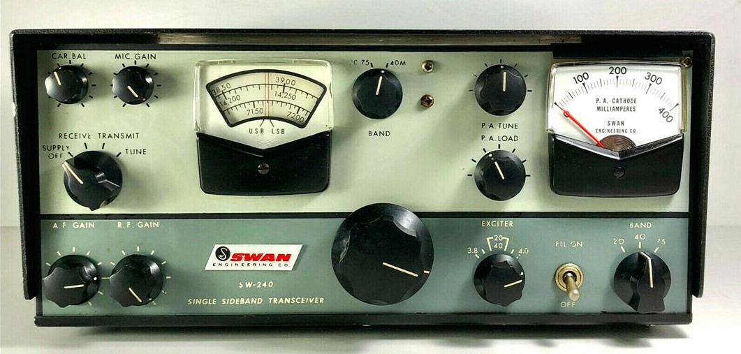
Swan 240?  Looking nice.

SDR adventures.

MAILBAG

Bill N8ET sent me some really nice Showa 9 MHz 8 pole crystal filters. 

Kevin AA7YQ Smoke jumper!  Building a hybrid SDR.HDR rig.  Launched blog. FB

Nick M0NTV working on similar HDR/SDR project.  Great video.

Grayson KJ7UM Hollow State Design – Launched a new blog.  Very FB!

Thomas K4SWL of SWL Post blog.  Kearsarge Mountain Transmission system.  And recent events.

Peter VK2EMU Poetry.  CW poetry.

Pete WB9FLW looking at DSB rigs…

Drew N7DA  Feels not like a real ham because he hasn’t built a quad from bamboo. Which type of landscape bamboo is best for antennas?

Ryan Flowers of MiscDotGeek.Com blog is also watching the Tally Ho YouTube videos of Leo Sampson. Wants to put a WSPR beacon on the Tally Ho. 

Joe KF5OWY  Working with diode ring mixers, trying to see the mixer action on his ‘scope. 1 and -1!

Jim AB9CN sent a cool idea about how to do a 20/17 Moxon.

Roy GM4VKI – I thanked him for his article in SPRAT about putting a 2n3904 on the output of an NE602 10P mod.  Brilliant.

Roger Hayward Told him that I really liked his Dad’s recent web site updates.

Farhan – Jokingly cursed me for showing him the Oscillodyne regen of Hugo Gernsback and Jean Shepherd.  “Now I will have to build this!”


Sunday, January 24, 2021

VBE Multiplier Makes KLH Receiver "Cool Running"

Yesterday I turned to the SolderSmoke wizards for advice on how to fix my KLH Model Twenty-one II FM receiver.   I had finally gotten the thing working -- it wasn't the speaker, it was the AF amp, probably one of the final transistors was blown.  I replaced the finals and the driver. For the finals I used a TIP29C and a TIP30C.  For the driver a 2N3906.    With this fix the receiver was sounding good, but the heat sink on the AF amplifiers was way too hot. 

If you look at the comments in yesterday's post, you will see some great suggestions on how to fix this problem.  The comments and Google led me to Alan W2AEW's YouTube channel and his video on a circuit called the VBE multiplier.  Voltage Base-Emitter multiplier.  I'd never used this circuit before.  It allows you to adjust the bias on the bases of the two transistors in a push-pull amplifier.  

This morning I built the circuit on a small piece of PC board.  There were just two components: a 10k trimmer pot and a 2N3904 transistor.  

With the little board installed, I adjusted the pot for a 1.2 volt difference between the bases of Q6 and Q7. I ended up with base voltage values almost identical to those called for in the KLH schematic. 

The receiver sounds very nice now, and is no longer on the verge of bursting into flames.  I even made up my own version of the pillow that KLH claimed was necessary for proper acoustic suspension.  

Sometimes it is nice to be able to listen to something other than the chatter on the ham bands. And it is fun to do so with a receiver that you have worked on.  

I even used some Desitin as a substitute for heat sink compound. 

Thanks to Rogier for the receiver, to ZL2DEX, K0EET, W2AEW and David McNeill for the good advice. And to Dale K9NN who sent me a box of parts from which emerged the 10k pot I used in this project.  Thanks guys. 73  

Saturday, January 23, 2021

KLH Model Twenty-One II AF Amplifiers Too Hot. Why?

I've been working on this nice old FM receiver that Rogier PA1ZZ sent me.  When I first tried it, it sounded terrible. I thought it might have been the speaker, but the speaker is fine. There was clearly something wrong in the AF amplifier.  Schematic above. Click on it for a better view. 

I ended up replacing the complementary pair of output transistors (Q6 and Q7) . The original had house brand designations -- I wasn't sure what to replace them with, so I just used a TIP29C and a TIP30C. With these transistors in there, the receiver sounds good. But the heat sink on the transistors is getting way too hot. I think the AF amplifier is now pulling about 1.4 amps, which is too much.

Another thing I did: I thought Q4 and Q5 might have been bad, so I replaced them with a 2n3904 and a 2n3906.

Why do you guys think the heat sink is getting so hot? What should I do? The supply on this receiver is 25V DC.

Friday, January 22, 2021

Jenny List's Favo(u)rite Things

Over on Hack-A-Day Jenny List (G7CKF)  has a really nice article about ham radio and homebrewing.  She truly has The Knack:  She got her start in radio electronics at age 9 when her parents gave her George Dobbs's Ladybird book.   

https://hackaday.com/2021/01/21/a-few-of-my-favorite-things-amateur-radio/

One of her paragraphs really seemed to capture the SDR-HDR conflict that we so often joke about: 

The age of the homebrew RF tinkerer may be at a close, at least in the manner in which I started it. Nobody at the cutting edge of radio is likely to be messing around with discrete transistor circuits in the 2020s, unless perhaps they are working with extremely exotic devices up in the millimetre wavelengths. It’s all software-defined radios, opaque black plastic boxes that deliver a useful radio experience on a computer but that’s it. No more homebrew, no more tinkering. 

Whew, good thing I'm not on the cutting edge.  It sounds kind of sad.  Oh well, that leaves more discrete transistors for us to tinker with.  

Jenny's Profile on Hack-A-Day: 

[Jenny List]: Contributing Editor and European Correspondent

Jenny List trained as an electronic engineer but spent twenty years in the publishing industry working on everything from computer games to
dictionaries before breaking out and returning to her roots.

She grew up around her parents’ small farm and blacksmith business in rural England, so making (and breaking) things is in her blood. Countless projects have crossed her bench over the years, though these days you’ll find her working with electronics and in particular radio, textiles for clothing and costume, decrepit classic cars, and real cider from first principles.

When she’s not writing for Hackaday she works on language corpus analysis software, designs and sells amateur radio kits, sits on the board of Oxford Hackspace, and is a freelance electronic design engineer and programmer.

Thanks Jenny! 

Thursday, January 21, 2021

Wednesday, January 20, 2021

Guilt Trip: Video on the Heath QF-1 Q Multiplier


Hack-A-Day had a nice post about this piece of gear: 

My radio emotions were swinging wildly as I watched this video. 

Readers may recall that over the years I have brutally cannibalized several QF-1s.   I was enticed into doing this precisely by the tuning cap that the videographer so alluringly describes.  It has a  built in 7:1 reduction drive!  How could I resist?  These wonderful caps live on in several of my homebrew rigs.  

I also put the conveniently sized metal cabinets to good use -- one holds frequency counters for my AM station, the other houses an Si5351 VFO/BFO that can be used with many rigs. 

After extracting the cap and putting the boxes to good use, I was left with the remainder of the circuitry.  I recently put even this stuff to use by using the coils to make a triple LC circuit filter for 455 kHz.  This may someday be used in a receiver.  So you see, I've not been wasteful. 

And the thing only cost 9 bucks back in the day...  So I didn't really do anything bad.  And besides, adding a regen circuit to a superhet is kind of backwards, right? 

But then the video producer started talking about how nice his QF-1 looks, even after more than 60 years.  And about how much it improved the performance of his AR-1.  And then, the kicker:  He said the QF-1s are now "relatively rare." 

I hang my head in shame.  I am a serial QF-1 killer.  And I don't know if I can stop. 


Tuesday, January 19, 2021

"The Transistor" 1953 Video from The Bell System


Interesting video. 

-- Good discussion of the transition from tubes.  

-- Go Arlington, Virginia! 

-- Nice video of Bardeen, Brattain and Shockley at work (Shockley does seem a bit off to the side). 

Monday, January 18, 2021

Kevin AA7YQ (Montana Smoke Jumper) Launches his SDR/HDR Build Blog

 
Earlier this month I posted a note from Kevin AA7YQ describing his effort to design and build a nice transceiver that mixes the best of SDR and HDR.   Kevin has launched a blog in which he will describe the project in more detail.  He is looking for constructive feedback and suggestions.  Check it out: 

http://aa7yq.blogspot.com/.

Thanks Kevin. 


Sunday, January 17, 2021

STOP. LISTEN. Shep on Building a Shortwave Receiver


Oh man, how could I have possibly missed this one?  Perhaps I didn't, but even if this one has been on the blog before, it is so good that it is worth repeating.  

Shep really captures the frustrations and joys of a teenage radio builder.  I could really identify with this.  It all reminded me of my heartbreaking effort to build the Herring Aid 5 receiver. 

So much cool stuff in this 1963 recording: 

-- The wonderful smell of radio service shops. 
-- The terrible shirt and tie choices of radio service guys. 
-- The truly dire consequences of mistakes in published schematic diagrams. 
-- The AGONY of not being able to get a homebrew radio to work. 
-- The JOY when you finally do get it to work. Shep's "whole life changed" when that happened. 
-- Hugo Gernsback, Lee DeForest and "unscientific scientists."

As the YouTube video plays, they show several covers of old Short Wave Craft magazines. At one point they show some homebrew phone rigs.  I think they look like my wooden box BITX rigs.  And the front panels are clearly Juliano Blue.  TRGHS. 

Here is the 1933 Oscillodyne article that launched Shep's effort: 


EXCELSIOR! 

Saturday, January 16, 2021

Nick M0NTV's Really Useful SDR Transceiver (video)


Even though I am more of an HDR guy, I really liked Nick's SDR rig.  I like the modular approach, with all the modules inside a transparent plastic box (see below).  Don't worry about the shielding Nick -- I had the same concern about my BITXs in wooden boxes, but they worked fine. 

Nick really did a great job on the video.  The bloc diagram was especially useful, both on the hardware and on the software.  Very cool.   It is nice to use this phasing approach,  with the digital magic happening at audio frequencies.   I fear that soon FPGAs and direct digital sampling will take the hardware fun out of these rigs.  We already have a bit of that with the RTL-SDR dongles. 

Very cool how the Teensy takes care of the 90 degree audio shift.   I had to do that with chips in my phasing receiver. When I first saw Nick's bloc diagram, I was looking for the audio phase shift network -- then he explained that that was in software, in the Teensy. 

Nicks arrangement for switching the filters is very nice.  

Thanks Nick!  


Designer: Douglas Bowman | Dimodifikasi oleh Abdul Munir Original Posting Rounders 3 Column