Podcasting since 2005! Listen to Latest SolderSmoke

Sunday, August 21, 2022

On our 17th Anniversary: SolderSmoke Podcast #179 -- TENTH ANNIVERSARY SHOW -- A Walk Down Memory Lane

On August 21, 2005 Podcast #1 was uploaded to our old GeoCities host. Just prior to that Mike KL7R set up a Yahoo Mail account.  I still use it. Yahoo sent me an e-birthday card! 


I put our 10th Anniversary Podcast on the YouTube Channel today.  Click above. Show notes below 

---------------------------------

22 August 2015

YESTERDAY MARKED 10 YEARS OF THE SOLDERSMOKE PODCAST
-- A clip: The first minutes of SolderSmoke #1
-- A trip down SolderSmoke memory lane.
-- The SolderSmoke lexicon -- words and phrases we use (a lot).

BENCH REPORT

-- Pete's antenna project.
-- Pete's new Blog: http://n6qw.blogspot.com
-- Bill's big amplifier problem fixed thanks to Allison KB1GMX.
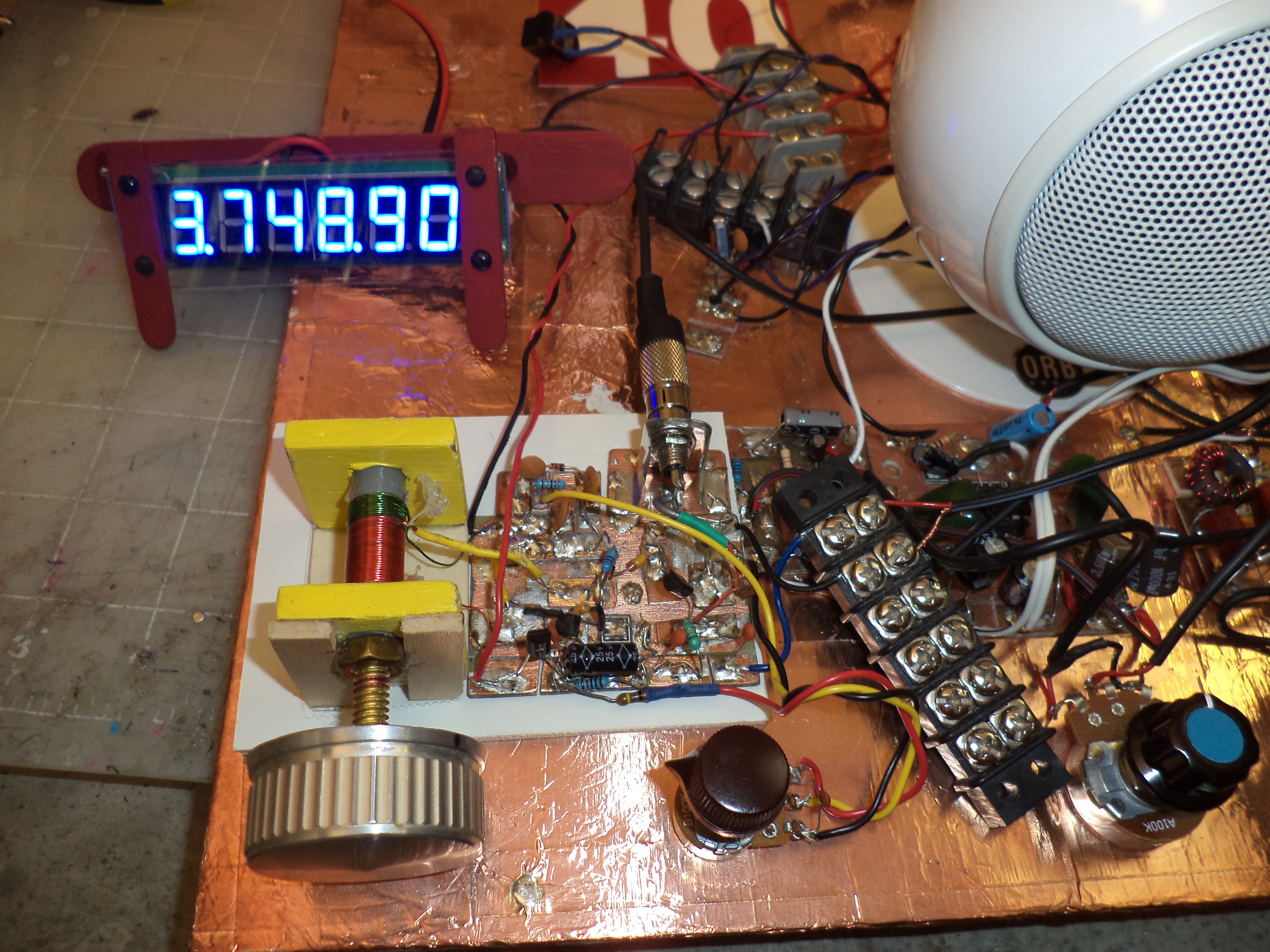
-- Six digit freq readout with an Altoids case.

THE Si5351 PHASE NOISE CONTROVERSY

-- ALL oscillators make noise.
-- Keeping things in perspective: It is 100 db down!
-- Observations and tests from LA3PNA, NT7S, and K0WFS:
http://k0wfs.com/2015/08/21/si5351-phase-noise-and-thd-tests-using-an-agilent-e4402b-spectrum-analyzer/

http://nt7s.com/2014/11/si5351a-investigations-part-7/

-- Try it, you'll like it! The benefits trying things on real rigs.

NEWS
Interviews on "QSO TODAY" with Eric 4Z1UG.
Horrible band conditions.
Looking at Saturn with telescope.

MAILBAG

Another recruit for the CBLA: Paul KA5WPL.
Ron G4GXO on Bell-Thorn and Eden9 SSB rigs.
Rupert G6HVY on Kon Tiki radio and Mr. Spock.
Mikele's Croation BITX rigs.
Dean AC9JQ's TIA.
Bryan KV4ZS will build an LBS receiver.
Dave Anderson give Pete good antenna advice.
Steve Smith moves in from the garage.
Pete has built 12 SSB transceivers. Intervention time?
------------------

Saturday, August 20, 2022

TRIGGER WARNING: Solid-Stating Old Tube (Thermatron) Gear (Including -- GASP -- R-390As)

Look at that.  Well, maybe some of you shouldn't. (I'm thinking of you Grayson.)  I found the Charles Smith YouTube channel while innocently looking for ideas on how to solid-state the HT-37 VFO assembly I recently bought on e-bay.  Charles Smith has some really great ideas in this area.  He solid-stated a Heath VF-1.  But he took it all to an extreme when he solid stated an R-390A.   Take a look at how he built the replacements for the thermatrons:  He used those plastic wall sockets that you screw into sheet-rock when you need to hang a picture.  This is real genius. He used the tube filament lines to carry DC to these new sockets. 


R390A Solid State Conversion Video #1:  https://www.youtube.com/watch?v=xhWzX874wYo

Charles Smith's YouTube Channel 

He has videos on the HQ-170 (DEAN:  Just say NO!) and the SP-600.  He also covers the HQ-110, which is uncomfortably close to my HQ-100.  

Who is Charles Smith?   What is his callsign?    Charles Smith is KV4JT.  Here is his QRZ page: 

He has some great humor and wisdom in his videos: Procedures that are difficult or more trouble than they are worth are called "bugger-bears."  He advises that if your IF cans are stuck, you should "find a way to unstick them!"  Indeed you should!  He builds a cool jig to hold the IF section of the R-390A while you are working on it.  He provides similar protection (with two long screws) to the VF-1.  

Even though some of you will have to go to therapy after seeing all this, I say THREE CHEERS FOR CHARLES SMITH! 

Friday, August 19, 2022

SolderSmoke's 2006 Interview with Farhan (and pictures from his 2019 visit)

Farhan in N2CQR shack with ET-2 on bench
October 2019

Here is the YouTube version of the SolderSmoke Podcast #34

 https://youtu.be/q-L4IE9f1aA

Farhan with Bob Bruninga WB4APR (SK) 

With Bill and Abe Lincoln

With Einstein

Correcting an Einstein equation

With Elisa


Tuning Bill's BITX 20

VK3IO's Wonderful Antenna Tuning System


I have been ridiculed because my manual antenna tuner (that is screwed into the wall of our car port) requires me to step outside into the cold or heat to change bands. 

On August 18, 2022  -- with my Hex Beam, not with the tuner -- I worked Ron VK3IO on 20 SSB.  Check out Ron's antenna tuning system.  He used the same balanced tuner that I use, but he has them set up for FIVE bands.  FB.  The wire antenna was working very well -- with 100 watts to the wire Ron was booming into Northern Virginia. 

Ron's QRZ.com page: 


Watch out for those spiders Ron!  


Thursday, August 18, 2022

Pete N6QW's First SolderSmoke Podcast


May 26, 2014. Pete Juliano's first SolderSmoke podcast. I think we both thought that this would be a one-time appearance. But one show led to another and soon we were in a permanent podcast collaboration. This was a very fortunate development, for me, for the podcast, for all our listeners, and for ham radio. Thanks Pete!

A Blast from the Past: The First SolderSmoke Podcast


I am gradually -- maybe one every few days -- going to put older SolderSmoke podcasts up on the YouTube channel.  Here is SolderSmoke Podcast #1.  This podcast was first uploaded on August 21, 2005. 

Be sure to check out the new Playlists on the SolderSmoke YouTube channel: 

Thanks to Ciprian YO6DXE for the wallpaper!  And thanks to Dave K8WPE for the idea of reposting "Old Smoke." 

Wednesday, August 17, 2022

Daylight Again on the Sunrise Net! Walter KA4KXX Builds a PTO


Dear Bill: 

I had never built a PTO, but after reading Farhan's Daylight Again Transceiver article I cobbled one together with parts and pieces I had on hand. My observations so far are as follows. 


1. The frequency-determining capacitors (shown on the schematic as three 470 pf) are very critical, so I feel the usual experimental cut-and-try technique is a must, even using all NP0 and C0G types. 

2. After I built the 2 MHz version like the article (see first photo), the stability was terrific, but when I tried building the companion Daylight Again crystal filter, I was only able to get a bandwidth of 1.6 kHz, which is too narrow for my taste in an SSB radio, so I decided to build the same filter design but with 11 MHz crystals, where I could easily achieve a 2.8 KHz BW. 

3. Therefore, now I needed a higher frequency VFO, so I merely reduced the capacitance (from about 1200 to 370 pf) without changing the coil and I am very impressed with the performance of my 4 MHz PTO (see second photo). The bandspread easily covers the entire 40M band, CW and Phone. 

4. However, whenever I transmit on the 40M Phone band, I like to first set my VFO within 10 Hz of the operating frequency. That way, if I talk for five minutes or so and get up to 15 Hz of drift (which is quite common with many radios when I operate portable outdoors in the sun and wind), it will not be noticable and I avoid receiving any "you are off-frequency" chastising. But the shortcoming I have with this PTO inductor is that the 1/4-20 bolt has a coarse thread, so it is very difficult for an old fellow like me to get within even 20 Hz of a particular frequency just using this common bolt. Therefore I believe a better choice would be the fine thread 1/4-28 two-inch brass threaded bolt which is available from industrial supply houses like McMaster-Carr. However, for CW use or those with a very steady hand, the 1/4-20 works well enough. 

5. I solved my fine tuning problem by adding a varactor circuit using a common 1N914 diode in series with a 100 pf capacitor, operating from 0 to 6 volts. Another advantage to adding this feature is that since I have not so far enclosed my PTO, I can mount the varactor potentiometer several inches from the PTO so my hand capacitance does not affect the frequency like when tuning with the bolt. 

6. An easy way to "do the math" in my case with the common Sanjian counters is to simply create a small lookup table listing half a dozen common frequencies and stick it on the radio. For example, 90% of the time in the morning I am tuned to my favorite SouthCars Net frequency of 7251, so using a BFO setting of 10,999.900, I simply set the PTO to 3,748.90 on the 6-digit 10 Hz resolution counter I normally use (see third photo). 

7. I am currently using my Daylight Again PTO on a daily basis with an NE602 receiver, and I am thinking of adding a locknut to the bolt so it does not wiggle when I jostle or move the radio, essentially giving me a crystal replacement oscillator that I can use for any single 40M frequency. To date I have been able to listen for hours at a time indoors without even any touch-up of the varactor fine tuning. 

8. Also, if continuous frequency readout is desired without building a noise filter circuit board, a separate power supply for the counter is a solution. For portable operation I use Lithium Polymer radio control model airplane batteries which are light, small, and cheap, so one 12V 2000 mAH battery for the transceiver (allows a half hour of transmitting at 15 watts) and a much smaller 12V 350 mAH battery with a series resistor to reduce the current and brightness of the counter has worked well for me. 

73, Walter KA4KXX 
Orlando, FL

Monday, August 15, 2022

Help SolderSmoke! Playlists for SolderSmoke YouTube Videos


In response to popular demand, I am putting up YouTube Playlists for SolderSmoke videos.  

Most of these lists are rig or project specific.  For example, my Hammarlund HQ-100 has its own playlist. 

But there is also one MASSIVE playlist with about 214 YouTube videos.   This one is especially good if you just want to keep SolderSmoke videos playing in the background as you work on rigs in your hamshack.  This video will also cause a big increase in the "SolderSmoke hours watched" metric of YouTube. 

Here are the Playlists (more will be added over the next few weeks): 

(20) SolderSmoke - YouTube

Here is the big Playlist with 214 SolderSmoke videos: 

(20) Polyakov Direct Conversion Receiver on 80 meters - YouTube


Thursday, August 11, 2022

What Coil for the Polyakov Input Circuit? How to calculate a coil value for resonance.


So,  what is the value for L1 and L2?   What coil should I use?  
Michael AG5VG had that question.  And so did I when I built this receiver.  See below for the process I used in answering this question. 

On Tuesday, August 9, 2022 at 10:53:32 PM EDT, Michael S  wrote:

Good Evening Bill,

My name is Michael and I really enjoy your podcast with Pete. I have also spoken with him in regards to the design of a 20M bandpass filter I made for a homebrew rig.  I am currently in the process of making a 20 meter DSB - SC type. Thank you for all the information that you speak and teach about during your podcast. I also enjoy the humor. It's great.

The Polyakov is a simple DC receiver and it amazes me and how the sound quality is. My question is, what is the turns on the toroid for the antenna primary side and the radio secondary and how did you figure out the turns because looking at the schematic it doesn't give that information that I can see. Also how you resonated it with the variable capacitor that looks like a 365pf air variable. 

Thank you for your time and keep up the great work on the podcast and the content on YouTube.

73s,
Michael
AG5VG

My response: 

Good questions Michael.   When I saw the SPRAT article I too was struck by the fact that it didn't give a value for the coil.  But DK2RS did have a large value variable capacitor... And he was billing this as a dual-band (80-40) rig.  So I figured he wanted that LC circuit to resonate as low as 3.5 MHZ and as high as 7.3 MHZ.  So, with a variable cap that goes up to 350 pf, what value L should I use?   I started by calculating the resonant frequency of the frequency mid-way point: 5.1 MHz.   I figured the variable cap should be around 162 pf at the mid-way point.  At this point I went to the on-line resonant frequency calculator: https://www.1728.org/resfreq.htm (a REALLY useful site!).   This site revealed I needed a coil of about 6 uH.  This put me in the ballpark.   But then -- with the site -- I tested it with the values of the variable cap I had on hand.  Mine was 23pf to 372 pf.  (you really need an LC meter to do this kind of thing). 

Again at the resonant freq calculation site:  23 pf and 6uH = 13.5 MHz           372 pf and 6 uH = 3.3688 MHz

This would have been OK, but I wanted to move the frequency range down a bit, so I tried. 6.5 uH 

23 pf and 6.5 uH = 13 MHz                 372 and 6.5uH = 3.23 MHz

Now, how many turns?  First look at the overall coil -- don't worry about taps at this point.    I use the Toroid Turns Calculator: http://toroids.info/

 Start by asking yourself "What core do I have on-hand?    Let's say you have a T-50-2 (red/clear).   The calculator shows you need about 36 turns.  Do-able, but physically kind of tight.  

I found a big core in my junk box.  A T-106-2.  The calculator showed I'd need about 22 turns on this core. It was much easier to get these turns on the larger core.  

You have to measure the core after you wind it to make sure you are at the desired inductance.   One side of the main coil went to ground, the other side to the top of the variable cap. 

 Now for the taps and secondaries:  The schematic shows a tap.  This is usually about 1/4 of the number of turns up from ground.   I picked about 5 turns, and wound a little tap in there at that point -- that tap went to the antenna.  You also have a secondary coil --no value is given, but based on experience I guessed around 5 turns -- I wound these turns on top of the primary one lead went to ground, the other went to the diodes and the switch. 

 The last thing to do is to see if the circuit resonates on both bands that you want to receive.  You can do this with a signal generator, or with the band noise:  Hook up an 80 meter antenna.  Put the cap closer to its max value and tune the cap -- can you hear band noise?  Or can you hear (or see on a 'scope) a signal at 3.5 MHz?   You should be able to peak it with the main cap.  Try to do the same thing on 40 meters -- here the variable cap should be closer to minimum capacity. 

 That's it.  That's how I did it.   You can do it too!   Good luck with the Polyakov.  

 One hint:  Building the VFO is the hard part.  You can get started by using a signal generator in place of the VFO.  Just make sure you have the level right -- around 620 mV input.  

 Good luck -- Let us know if you have trouble. And please let us know how the project goes.   

 73    Bill    N2CQR  

20 meter rig built by AG5VG

Wednesday, August 10, 2022

Vasily Ivanenko on Vladimir Polyakov's Subharmonic Detector


Our old friend "Vasily" sent in a very insightful comment about the Polyakov receiver.   It was so good that it merits a blog post of its own.  Here it is.  Thanks Vasily! 

Vasily IvanenkoAugust 9, 2022 at 12:49 AM

Thanks Bill. My own experiments at HF with subharmonically pumped Schottky diode mixers show clearly that almost every mixer parameter we measure is worse than our classic balanced mixer topologies. Definitely 2LO-RF isolation was better than other unbalanced mixers without the need for a transformer.

I guess it's appealing for low-complexity receiver builders. For zero IF receivers, I like and run my LO at 1/2 RF frequency and then use a doubler -- that's a great advantage for
a DC/ Zero-IF receiver and a built-in feature for the subharmonic mixer.

The SH mixer becomes quite appealing at SHF to mm-wave lengths where making a quiet, temp stable LO gets rather expensive and tricky.

Subharmonically pumped mixers can also work at odd integers if the mixer LO/RF drive is balanced and designed to produce distortion that for example, triples the LO frequency. Rohde & Schwarz had a 40.1 GHz spectrum analyzer with one --- and if the LO was 13 GHz while the RF was 39.5 GHz, this gave an IF output of 500 MHz in 1 particular circuit. Really amazing design work. Here's an interesting URL:

https://www.eravant.com/products/mixers/subharmonically-pumped-mixers

The SH mixer has been around for > 4 decades. The oldest SH mixer paper I've got in my library is from Schneider and Snell from 1975. I don't think they invented the SH, but this pair helped popularize it for the world and design work continues today.I've seen optical SH mixers with I/Q outputs in research papers.

Here's the abstract and citation:

Harmonically Pumped Stripline Down-Converter

M. V. Schneider, W. W. Snell
Published 1 March 1975
Physics, Engineering
IEEE Transactions on Microwave Theory and Techniques

A novel thin-film down-converter which is pumped at a submultiple of the local-oscillator frequency has given a conversion loss which is comparable to the performance of conventional balanced mixers. The converter consists of two stripline filters and two Schottky-barrier diodes which are shunt mounted in a strip transmission line. The conversion loss measured at a signal frequency of 3.5 GHz is 3.2 dB for a pump frequency of 1.7 GHz and 4.9 dB for a pump frequency of 0.85 GHz. The circuit looks attractive for use at millimeter-wave frequencies where stable pump sources with low FM noise are not readily available.

Best to you!

Tuesday, August 9, 2022

Polyakov Direct Conversion Receiver on 80 Meters (video)

In today's episode I put the switch in the open position turning the receiver into an ordinary Direct Conversion receiver with a single diode as the detector. I find that it works pretty well on 80, but probably not as well as it does on 40 (where it is in full Polyakov mode). (Yesterday I demonstrated the receiver in action on 40 and provided details on the circuit. See: https://soldersmoke.blogspot.com/2022/08/polyakov-ra3aae-direct-conversion.html)

You will notice that when I throw the switch, but before I retune the input LC network, you can still hear the signal from the previous band. So when I have it in 40 and I throw the switch to open, you can still hear the 40 meter signal. Apparently one diode will (poorly) demodulate a signal with the VFO running at HALF the operating frequency. I saw this in the real world receiver and also saw it in an LTSpice simulation. In LTSpice the signal level drops significantly when I go to just one diode: From 50 mv peak to 15 mv peak, but it can still be heard. Something similar happens when I go from 80 to 40. When I close the switch and suddenly have two diodes and a 3.5 MHz VFO trying to demodulate the 80 meter signal, I can still hear the 80 meter signal, but it is much weaker and a lot more noise is getting through. Again, I saw this in the real world and in LTSpice. It looks as if with the two diodes, the 3.5 MHz signal is being sampled twice each VFO cycle. This may result in some output in the audio range. But again, it is much weaker.

Monday, August 8, 2022

Polyakov (RA3AAE) Direct Conversion Receiver: 40 meter DC RX with VFO at 3.5 - 3.6 MHz (with video)

I've been reading about Polyakov (or "sub-harmonic") Detectors for a long time: 

https://soldersmoke.blogspot.com/search/label/Polyakov--Vladimir

But until now, I never built one.  Recently,  Dean KK4DAS and the Vienna Wireless Makers group have been building a Direct Conversion receiver.  Their receiver uses an Si5351 as the VFO, but of course Dean and I have decided to try to do things the hard way by building non-digital VFOs.  At first we just came to the conclusion that my earlier Ceramic Resonator VFO wasn't much good (it drifted too much).  This led us into standard Colpitts and Armstrong VFOs, and the fascinating world of temperature compensation.  Then I remembered the Polyakov circuit -- this would allow us to use a 3.5 MHz VFO on the 7 MHz band.  Lower frequency VFOs are easier to stabilize, so I started building my first Polyakov receiver.  You can see the results (on 40 meters) in the video above. 

I started working with a circuit from SPRAT 110 (Spring 2002). Rudi Burse DK2RS built a Polyakov receiver for 80 and 40 that he called the Lauser Plus.  (Lauser means "young rascal" or "imp" in German.) For the AF amplifier, I just attached one of those cheap LM386 boards that you can get on the internet.  With it, I sometimes use some old Iphone headphones, or an amplified computer speaker. 

The Polyakov mixer is a "switching mixer."  The book excerpt below shows how I understand these circuits.  The enlightenment came from the Summer 1999 issue of SPRAT (click on the excerpt for an easier read): 


Leon's circuit shows us how a simple switching circuit in which the switches are controlled by the VFO can result in an output that has the sum and difference components. That is the hallmark (and most useful part) of real mixing.  Remember -- we say that mixing happens in non-linear circuits when the passage of one signal depends on what is happening with the other signal.  A switch is as non-linear as you can get! And that switch is being controlled by the VFO.  

In a Direct Conversion receiver we usually run the VFO at the operating frequency. This results in audio just above and just below the operating frequency. 

The Polyakov Direct Conversion circuit is a bit different.  It has the switches (the diodes)  turned on twice each cycle:  When the VFO voltage goes to a positive peak, this turns on one of the diodes.  When the VFO goes to a negative peak, this turns on the other diode.   So in effect the switch is being turned on TWICE each cycle.  So with the Polyakov you run the VFO at HALF the operating frequency.  For a DC receiver designed to run around 7.060 MHz, you build a VFO at around 3.53 MHz.  This has some immediate advantages.  My favorite is that it is easier to get a VFO stable at a lower frequency.  It is easier to stabilize a VFO at 3.53 MHz than it is at 7.060 MHz. 

When you open that SW 1 switch in the Lauser Plus, you no longer have a Polyakov mixer.  Now you just have a diode mixer.   It will be opening and closing once each cycle at the VFO frequency.  DK2RS used this to cover not only the 40 meter band (in Polyakov mode) but also the 80 meter band (in single diode detector mode).  That is why DK2RS has that big variable capacitor in the input circuit -- that LC circuit needs to tune all the way down to 3.5 MHz and all the way up to around 7.3 MHz.  (I used a coil of about 6.5 uH to do this.) 

With just one diode and operating at 80 meters, it works, but not as well as it does in the Polyakov mode on 40.  I can pick up 80 meter signals, but in this mode there seems to be more of an "AM breakthrough" problem. "Experimental Methods in RF Design" on page 8.11  describes what is going on (the last sentence is most relevant here): 

Here are some very good links with information on the Polyakov receiver: 


LA8AK SK: http://www.agder.net/la8ak/   Almost seventeen years after his death he continues to help his fellow radio amateurs through his web sites.  TNX OM!  FB! 


I will post a video tomorrow showing the receiver in operation on 80 meters.  

Three cheers for Vlad Polyakov, RA3AAE

Designer: Douglas Bowman | Dimodifikasi oleh Abdul Munir Original Posting Rounders 3 Column