
I've been watching with great interest Mike WU2D's excellent series on VFO construction. His second video is especially interesting because he talks about how we can use a split stator differential capacitor to build a temperature compensation circuit that will allow us to "dial in" the proper amount of temperature compensation.
The heart of this circuit is the split stator differential capacitor. The stator is split; but there is a common rotator. As the rotator moves, the capacity across one part of the capacitor increases while the other part decreases -- thus the total capacity remains unchanged. If we connect two capacitors of the same capacitance BUT OF OPPOSITE TEMPERATURE CHARACTERISTICS -- we can use this split stator cap to select just the right amount of temperature compensation. Very cool. Even cooler: Mike actually built a split stator differential capacitor. That, my friends, is dedication.
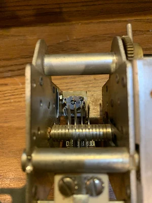
I was sitting here this morning thinking about all this when it occurred to me that right in front of me was a capacitor that might be relevant to all this (see above). I bought it on e-bay one year ago after Pete N6QW had alerted me to it. It is the main tuning capacitor from an HT-37 transmitter. What attracted us was the big anti-backlash mechanism. But now I realized that it had another charming feature.
Looking at it a bit more closely I saw a split stator differential cap just like the one that Mike had made. Attached to the two rotors were two tubular capacitors. The three caps are in parallel with the main tuning cap. Bingo -- this is a temp compensation circuit.
I checked the HT-37 manual. The manual says that temp compensation is set at the factory. OK. But the schematic does not show the split stator caps and the two tubular caps (see below). Could it have been that this circuit was added later perhaps to address drift? (We do see it in the HT-32B schematic -- see below.)

HT-37 VFO SCHEMATIC
Anyway, it was very cool to find this example of the circuit Mike was discussing. In the photo at the beginning of this post you can see the three caps. Below you can see the split stator cap in the background.
In the comments a reader points out correctly that this circuit was discussed in the ARRL book "Single Sideband for the Radio Amateur." Indeed, it is on page 51 of the 1970 edition, ARRL gave credit for the circuit to Hallicrafters:


HT-32B VFO Circuit
Joe Carr K4IPV (SK) also discussed this circuit. In his article in Popular Electronics in August 1993, he too gave credit to Hallicrafters. Carr also gave some detailed instructions on how to use the circuit to stabilize a VFO. See pages 78 and 79 of the August 1993 Poptronics:
I'm sure this is in an edition of the ARRL SSB Manual. I thought it derived from a Hallicrafter's circuit, so it might have been an excerpt from a QST review,back when the reviews inckuded partial schematics.
ReplyDeleteRight you are Michael. I found it in the 1970 ARRL SSB book. I updated the post and also included a link to a 1993 Poptronics article by Joe Carr that discusses this circuit. Thanks and 73 Bill
ReplyDeleteI have used this method on several transceivers going back to the 70's. Later replaced with a temperature sensor feeding an op map and Varicap diode.
ReplyDeleteI've read it in a RSGB book too years ago but it's all good stuff and I love watching his videos.
ReplyDeleteThe FT-101 VFO that you used in the Myth Buster rig also has the split stator capacitor in it. If you look in the bottom side you will see it. And of course it is the schematic also. This is a very neat trick to learn about.
ReplyDelete