Podcasting since 2005! Listen to Latest SolderSmoke

Showing posts sorted by date for query Myth. Sort by relevance Show all posts

Friday, May 17, 2024

Band Imaging Rigs (Receivers and Transceivers) -- Video from WA7MLH


In the video above (from 16 years ago) we see Jeff Damm, WA7MLH's  band-imaging receiver for 75 and 40 using an IF of 1.750 MHz and a VFO of 5.2 - 5.7 MHz,  For a signal at say 3.579 MHz (!) you subtract the signal from the VFO and you end up at the IF.  For a signal at say 7.030 MHz you subtract the VFO frequency from incoming signal and get to the IF.  (By the Hallas rule you get sideband inversion on 75/80 meters, but Jeff was on CW so this doesn't really matter.)  

Sixteen years ago this receiver was a work in progress and Jeff was having some trouble with the bandpass filters. I had similar trouble with bandpass filters. Like Jeff, I eventually got this sorted.  

I was happy to see a comment from my friend Joanthan-san on Jeff's old video.  

Jeff has an awesome and rececntly updated QRZ site:  https://www.qrz.com/db/wa7mlh

Band imaging like this is an old idea, and a very good one:  I used a slightly different scheme:   Start out planning on using a single conversion design.  Pick two bands you are interested in.  Select an IF midway between the two.  Build a single VFO that --when added to the incoming (or the outgoing) signal will get you to one of the bands, and when subtracted from the signal will get you to the other one.  Bob is then your uncle.  Two bands, with minimal switching. 

I got started with band switching with my Mythbuster rig:  I would get 75 and 20 meters.  The IF was midway between the two at 5.2 MHz.   My VFO (from an old Yaesu FT-101) ran around 9 MHz.  Boom, it worked, with the added benefit of receiving and transmitting LSB on 75 and USB on 20 with no switching of the BFO/Carrier Oscillator.

Then I did 17 and 12 meters.  Kind of a WARC-band special.  IF was at 21.4 Mhz.  VFO ran around 3.5 MHz.  So by adding the incoming modulated signal 18 MHz signal and the VFO, you get to 17 meters.   By subtracting the VFO from the incoming 24.9 MHz signal you get to 12 meters.  And both are on USB (apply the Hallas rule), so again, no switching of BFO/Carrier frequencies are required. 

Finally,  at solar max, I built rigs for 15 and 10.  Here the IF was 25 MHz.  Again the VFO was around 3.5 MHz.  Adding the incoming 21 Mhz signal to the VFO gets you to 25 MHz, subtraction of the VFO frequency from the in coming 28 MHz signal takes you to 25 Mhz and thus 10 meters.  Again, no sideband inversion (Hallas rule).   Both signals are USB and stay on USB. (I built two versions of this rig -- one stays in Virginia, the other is heading to the Dominican Republic.) 

In the ARRL book QRP Classics, there is an article from the 1990 Handbook entitled "A Band-Imaging CW Receiver for 10 and 18 MHz."  The article may have been based on a receiver built by Dave Newkirk AK7M (Rod Newkirk's son). Unfortunately in the write-up for the ARRL handbook, the drafters repeat the oft-repeated myth about how 9 MHz IF and a 5.2 MHz VFO would supposedly produce LSB on 75 and USB on 20.  This just doesn't work.   But if you put the IF at 5.2 MHz and the VFO at 9 MHz, it does work, as demonstrated by my Mythbuster rig. 

Wednesday, May 31, 2023

Farhan VU2ESE FDIM Interview (#6) by Bob Crane W8SX: VHF Rig, sBITX, and Good News on Raspberry Pi 4

It was great that Bob was able to catch up with Farhan and talk to him about his VHF rig and about the sBITX. 
    
Farhan said that the VHF rig (the BITX23) was presented at the homebrew show-and-tell as a project.  The idea was to encourage others to get into VHF homebrewing.  Farhan points out that many of us are reluctant to go into VHF building, thinking that we need special or exotic test gear. No true says Farhan.   He is trying, with this rig, to bust this myth.  FB.
    
On the sBITX, Farhan points out that he too -- coming as he does from the homebrew tradition -- finds some of the modern rigs quite intimidating.  So he designed the sBITX to be less intimidating.  It is, he says, a tinkerable rig that could be homebrewed. It is all open source.  
    
Farhan points out that the rig is built around the Raspberry Pi 4, a device that has recently been hard to obtain.  This has driven up the price of the sBITX a bit.   But good news:  Farhan says that the word on the street is that the Raspberry Pi 4 will be available in quantity starting at the end of June.  

Here us Bob's interview with Farhan: 

http://soldersmoke.com/VU2ESE23.mp3

BITX23 VHF Rig

And here is a video of Farhan describing the BITX23: 

Thanks Fathan!  Thanks Bob! 

Wednesday, October 13, 2021

SolderSmoke Podcast #233: PIMP, Boatanchors, Novices, MMM, Heathkits, DC Receivers, Mailbag


SolderSmoke Podcast #233 is available. 

http://soldersmoke.com/soldersmoke233.mp3

Travelogue: Cape Cod. SST. Marconi Site.

The WFSRA:   The World Friendship Society of Radio Amateurs.


Pete's Bench:

The Pimp.
The NCX rig.
The Collins.
The many DC receivers built worldwide.
The parts shortages are real! Several key radios on hold. Si5351 sub.
Talk to G-QRP convention

Bill's Bench:

FT-8. Not for me. I tried it.
Novice Station Rebuild.
Globe V-10 VFO Deluxe.
Selenium rectifier removal CONTROVERSY?
Not crazy about my Novice station. Not crazy about CW. 
Mate for the Mighty Midget. Again. 
Mike W6MAB -- Detector problems LTSPICE Check
One more mod for MMM RX. Ceramic filter at 455.
Dropped screw inside tubular cap on Millen 61455 transformer. 
Talk to the Vienna Wireless Society
Thinking of a Moxon or a Hex beam.


BOOK REVIEW Chuck Penson WA7ZZE New Heathkit Book. http://wa7zze.com


Mailbag

-- New SPRAT is out! Hooray!
-- Todd K7TFC sent me copy of Shopcraft as Soulcraft. FB.
-- Dean KK4DAS building an EI9GQ 16 W amp. FB.
-- Jack NG2E Getting close on Pete's DC receiver.
-- JF1OZL's website is BACK!
-- Tony K3DY sent link to cool books. 
-- Sheldon VK2XZS thinking of building a phasing receiver.
-- Peter VK2EMU has joined the WFSRA. FB!
-- Ned KH7JJ from Honolulu spotted the Sideband Myth in the AWA video.
-- Chris M0LGX looking at the ET-2, asks about the variometer.
-- Pete Eaton Nov 64 anti HB rant in november 1964 QST. Wow.
-- Josh Lambert Hurley spreading FMLA stickers in the UK. FB
-- Stephen VE6STA getting ready to melt solder.
-- Got a great picture of Rogier PA1ZZ back on Bonaire.
-- Farhan reading the manual of Hans's new digital rig.
-- Paul G0OER wonders if FMLA getting ready to move on 5 meters.

Saturday, August 21, 2021

W2EWL's "Cheap and Easy SSB" Rig -- And The LSB/USB Convention Myth


In March 1956 Tony Vitale published in QST an article about a "Cheap and Easy" SSB transmitter that he had built around the VFO in an ARC-5 Command Set transmitter.  Vitale added a 9 MHz crystal-controlled oscillator,  and around this built a simple phasing generator that produced SSB at 9 MHz.  He then made excellent use of the ARC-5's stable 5 - 5.5 MHz VFO.  His rig covered both 75 meters and 20 meters.  Here is the article:

http://nebula.wsimg.com/2b13ac174f7f2710ca2460f8cf7d6b8b?AccessKeyId=D18ED10DA019A4588B7B&disposition=0&alloworigin=1

Because it used the 9 and 5 frequency scheme, over the years many, many hams have come to think that Vitale's rig is the source of the current "LSB below 10 MHz, USB above 10 MHz." This is  wrong.   An example of this error popped up on YouTube just this week (the video is otherwise excellent): 


First, Vitale's rig had a phasing SSB generator. All you would need to switch from USB to LSB was a simple switch.  And indeed Vitale's rig had such a switch. Pictures of other Cheap and Easy transmitters all show an SSB selection switch. So with a flip of the switch you could have been on either USB or LSB on both 75 and 20.  With this rig, you didn't even need sideband inversion to get you to 75 LSB and 20 USB. 

Second, even if hams somehow became so frugal that they wanted to save the expense of the switch, leaving the switch out (as suggested above) would NOT yield the desired "75 LSB 20 USB" that the urban legend claims that W2EWL.   As we have been pointing out, a 9 MHz SSB generator paired with a 5 MHz VFO (as in the Vitale rig) will NOT -- through sideband inversion -- yield LSB on one band but USB on the other.   

W2EWL's rig could not have been the source of the LSB/USB convention.  I still don't know where the convention came from. I am still looking for the source. 

But leaving the LSB/USB convention issue aside, Tony Vitale's rig is an excellent example of early SSB homebrewing, and of a very clever use of war surplus material.  In the January 1992 issue of Electric Radio magazine, Jim Musgrove K5BZH writes of his conversations with Vitale about the Cheap and Easy SSB.  Tony told Jim that this rig came about because the Central Electronics exciters required an external VFO -- they recommended a modified BC458.   B&W had recently come out with a phase shift network. Vitale went ahead and built the whole rig inside a BC458 box.  FB Tony! 

In the December 1991 Electric Radio, Jim K5BZH reports that Tony was recruited into the ranks of SSBers when he watched a demonstration of SSB by Bob Ehrlich W2NJR in November 1950. Tony very quickly started churning out SSB rigs.  His daughter Trish Taglairino recounted that when her father had "done something great again" there would be a parade of hams to the basement shack.  About 30 guys showed up when Tony put his first SSB rig on the air -- they sent out for beer.  

Thanks to Jim for preserving so much SSB history. 

Monday, July 26, 2021

QST Repeatedly Got Sideband Inversion Wrong

It kind of pains me to do this. These articles are from a long time ago, and the author is an esteemed  Silent Key,  but the myth about the origins of the USB/LSB convention is still out there, and as a homebrewer of SSB gear I feel obligated to point out these examples of the error that that myth is based on.   

Last Friday, Pete WB9FLW and I were talking about homebrewing SSB rigs.  I recommended a series of QST articles by Doug DeMaw.  "Beginner's Bench:  The Principles and Building of SSB Gear" started in QST in September 1985. There were at least five parts -- it continued until January 1986. (Links to the series appear below.) I hadn't looked at these articles in years, but when I did, a big mistake jumped right out at me:  In the first installment, on page 19, Doug  makes the same mistake that he made in his Design Notebook:

"Now comes the conversion section of our SSB generator.  We must move (heterodyne) the 9-MHz SSB signal to 3.75-4.0 MHz. Our balanced mixer works just as it does in a receiver. That is, we inject the mixer with two frequencies (9 MHz and 5 MHz) to produce a sum or a difference output frequency (9 - 5 = 4 MHz, or 9 +5 = 14 MHz) If we are to generate 75 meter SSB energy, we must chose the difference frequency. We could build an 20-meter SSB transmitter by selecting the sum of the mixer frequencies. The RF amplifiers and filter (FL2) that follow would then have to be designed for 14-MHz operation.  In fact, many early two-band homemade SSB transmitters were built for for 75 and 20 meters in order to use this convenient frequency arrangement.  The use of upper sideband on 20 meters and lower sideband on 75 meters may be the result of this frequency arrangement (the sidebands become inverted when switching from the difference to the sum frequency.) " 

Those last two sentences are incorrect.  They repeat the "Myth," or the "Urban Legend" about the origins of the LSB/USB convention.  Contrary to what many hams now believe, with 9 MHz filter and a 5.2 MHz BFO it takes more than just switching from sum frequency to difference frequency to invert one of the sidebands. 

There are two conditions needed for sideband inversion to take place:  

1) You have to be taking the difference product (DeMaw got that right) 

2) The unmodulated (VFO or LO) signal must be larger than the modulated signal. (DeMaw and the ARRL obviously missed that part.  Repeatedly.) 

This is another way of stating the simple, accurate and useful Hallas Rule:  Sideband inversion only occurs when you are subtracting the signal with modulation FROM the signal without modulation. 

For DeMaw's claim to be correct, one of the SSB signals going into the balanced mixer would have to invert, and the other would have to not invert.  Let's see if that happens: He has the sideband signal being generated at 9 MHz and the VFO running around 5 MHz. 

9 - 5 = 4  But we are not subtracting the modulated signal FROM the unmodulated signal.  SO NO INVERSION

9 + 5 = 14   We are not subtracting at all.  SO NO INVERSION.  

Doug's convenient frequency scheme WOULD work if he'd just switch the frequencies of the filter and the VFO.  With a sideband generator on 5.2 MHz and a VFO around 9 MHz you do get the happy 75  LSB, 20 USB arrangement without the need to switch the carrier oscillator/BFO frequency.   That is what happened in the Swan 240, and that is what I have in my Mythbuster rig. I am listening to both 75 LSB and 20 USB without changing the carrier oscillator/BFO frequency.  My filter/BFO/product detector is set up for USB.   With this arrangement the 75 meter LSB signals DO invert, and the 20 meter USB meter signals do not, so both are able to make use of my USB BFO/product detector without shifting the BFO frequency. 

This error shows up again in DeMaw's the May 1989 QST article "A Four Stage 75-meter SSB Superhet" (reprinted in the ARRL's QRP Classics book).  Here he writes: 

"Should you want to cover both the 75- and 20-meter bands you can build a 20-meter version of FL-1 and band switch the two filters. As with the 75 meter only version, an IF of 9.0 MHz (Y1) is required. With this arrangement the 20 meter band will tune backwards from the 75 meter band, but upper- and lower-sideband reception will occur, as required, without changing the BFO frequency (Y2). This two band scheme with a 5-MHz VFO is an old one!"   NOTE: FL1 is the bandpass filter, not the IF filter.  

Doug's mistakes in this area may simply be due to the fact that he was more of a CW guy.  And this is something that is quite easy to confuse:  9 and 5 will get you to 75 and 20, but you have to make sure the VFO is at 9 if you want to make use of sideband inversion and avoid having to shift the BFO/ carrier oscillator.   I've made this mistake myself: 

In October 1993 I wrote to DeMaw about his Four Stage 75 meter SSB Superhet.  I think I was looking for details on how to put it on 20 meters.  As I recall, Doug wrote back telling me to just pick 20 meter values for the input bandpass filter.  Had I done so, I would have discovered that  -- for the reasons cited above -- this just wouldn't have worked on 20.  His BFO and filter were set up to receive LSB signals. That's fine for the incoming 75 meter LSB signals.  But on 20 -- contrary to DeMaw's thinking -- there would be NO sideband inversion. I'd be trying to listen to 20 meter USB signals with a receiver set up for 20 meter LSB.  

Did anyone else notice these errors.  Were there ever errata notices in QST on this?  

This is a reminder that you should take all technical articles and schematics with a grain of salt.  Many contain errors. We are all human, and this is a complicated subject with lots of details. 


Thursday, July 22, 2021

The Unicorn! A 75 LSB /20 USB Receiver (That Can't Work)


Don't get me wrong -- I'm a huge fan of Doug DeMaw.  His books and articles are a treasure trove for ham radio homebrewers.  Also, Doug was an honest guy who admitted in the preface to his QRP book that at times he did not fully understand the circuits he was building; that kind of honesty is rare,  and is very helpful to amateurs who struggle to understand the circuits we work on.  

But everyone makes mistakes, and Doug made one in his "W1FB Design Notebook."  I present it here not as a "gotcha" effort to nitpick or sharpshoot a giant of homebrew radio, but because this error illustrates well the depth of the 75 LSB/20 USB myth, where it comes from, and how important it is to really understand sideband inversion.     Here is the mistake: 


That's just wrong.  A receiver built like this will not allow you to listen to 75 LSB and 20 USB "without changing the BFO frequency." (Am I the first one to spot this error?  Didn't anyone build this thing, only to discover that it, uh, doesn't work?)

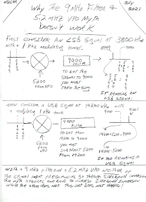
Here's a little drawing that I think illustrates why the mythical scheme will not work: 


All confusion about sideband inversion could be avoided with the simple application of what I think we should call "The Hallas Rule"

"Sideband reversal occurs in mixing only  if the signal with the modulation is subtracted from the signal that isn't modulated."  

Be careful here:   I think some arithmetic carelessness is responsible for much of the myth. Taking the difference frequency is not enough to produce sideband inversion. Read the Hallas Rule carefully:   For sideband inversion to occur, the signal with the modulation must be subtracted FROM the signal without the modulation.
--------------------------------------------- 
About the Swan 240's SSB generation scheme: 

I first stumbled on this problem when building my first SSB transmitters in the Azores.  I was using a VXO,  and a filter pulled out of a Swan 240 (5.173 MHz).  I started with VXO crystals at around 12.94 MHz.  The rig worked,  but I couldn't pull the VXO crystals very far.  So I switched to crystals at around 23.3 MHz (you can pull higher frequency crystals farther).  But look what happened:  My Carrier Oscillator frequency had been set up to receive USB signals on 17 Meters.  With the 12.94 MHz rocks, that worked fine:   18.150-12.977 = NO INVERSION.  But it all changed when I went to the 23 MHz VXO rocks:  23.323-18.150 = INVERSION!   This had me scratching my head a while.  I had to draw myself little spectrum pictures (like the one above) before I realized what had happened.  To get it to work -- to get it to produce USB on 17 meters -- I had to move the Carrier Oscillator to the other side of the passband. Good thing that Swan 240 came with TWO BFO crystals (5.1768 MHz and 5.1735 MHz). I just had to change the crystal. 

For 75 and 20 meters, the Swan 240 uses the correct 5.173 MHz filter with a 9 MHz VFO to get the happy situation of 75 meter LSB and 20 Meter USB WITHOUT changing the BFO/Carrier Oscillator frequency.  This is the Mythbuster scheme.  Unlike Doug's receiver, it works.  The scheme also works in the Swan 240 on 40 meters because for 40 the Swan rig has the VFO running from 12.073 MHz to 12.513 MHz. Here too, no change in the BFO/Carrier Oscillator  frequency is needed. But the Swan recommended a modification that would allow operation on 20 LSB and 75/40 USB!  It used a BFO/Carrier Oscillator crystal of  5.1765 MHz and a switch mounted on the front panel.  Luckily,  my junker Swan (acquired from HI8P in the Dominican Republic) had the second crystal -- mine was 5.1768 MHz.  It was that crystal that allowed me to get my Azorean SSB transmitter to work using the 23.9 MHz VXO rocks.    

Thursday, June 17, 2021

The Stubborn Myth about USB and LSB

It  has been repeated so often and for so long that many of us have come to believe it.  I myself believed it for a while.   Like many myths, it has a ring of truth to it.  And it is a simple, convenient explanation for a complex question: 

Why do ham single sideband operators use LSB below 10 MHz, but USB above 10 MHz? 

Here is the standard (but WRONG) answer: 

In the early days of SSB, hams discovered that with a 9 MHz SSB generator and a VFO running around 5.2 MHz, they could easily reach both 75 meters and 20 meters (True). And because of sideband inversion, a 9 MHz LSB signal would emerge from the mixer as an LSB signal (True), while the 20 meter signal would emerge -- because of sideband inversion -- as a USB signal (FALSE!)  That sideband inversion for the 20 meter signal explains, they claim,  the LSB/USB convention we use to this day. 

Why this explanation is wrong: 

There is a very simple rule to determine if sideband inversion is taking place:  If you are subtracting the signal with the modulation FROM the signal without the modulation (the LO or VFO) you will have sideband inversion.  If not, you will NOT have sideband inversion.

So, you just have to ask yourself:   For either 20 or 75 are we SUBTRACTNG the Modulated signal (9 MHz) from the unmodulated signal (5.2 MHz)? 

For 75 meters we have:   9 MHz - 5.2 MHz =  3.8 MHz    NO.  We are not subtracting the modulated signal from the unmodulated signal.  There will NOT be sideband inversion. 

For 20 meters we have 9 MHz + 5.2 MHz = 14.2 MHz.     NO.  No subtraction here.  No sideband inversion.   

So it is just arithmetically impossible for there to be the kind of happy, easy, and convenient  USB/LSB situation described so persistently by the myth. 

---------------------------------

We discussed this several times on the podcast and in the blog: 

https://soldersmoke.blogspot.com/2015/05/sideband-inversion.html

https://soldersmoke.blogspot.com/2012/05/usblsb-urban-legend-debunked.html 

This myth shows up all over the place: 

We see the myth here: 

http://n4trb.com/AmateurRadio/Why%20The%20Sideband%20Convention%20-%20formatted.pdf

Here the web site owner warns that this is "highly controversial."  Really?  Arithmetic? 

http://9m2ar.com/lsb7.htm

The myth is very old.   Here is a clip from a 1966 issue of "73" magazine: 

https://worldradiohistory.com/Archive-DX/73-magazine/73-magazine-1966/73-magazine-01-january-1966.pdf

Finally, to my disappointment, I found the myth being circulated by the ARRL, in the 2002 ARRL Handbook page 12.3: 


The fact that the Handbook attributed this to a desire to "reduce circuit complexity" by not including a sideband switch should have set off alarms.  We are talking about hams who built their own SSB rigs, usually phasing rigs.  A sideband switch would not have added significant circuit complexity. I think they could have handled it. 

It is interesting that earlier ARRL Handbooks do not repeat this myth.  I found no sign of it in Handbooks from 1947, 1959, 1963, 1973, and 1980.  And I found no sign of it in several editions of that great ARRL book "Single Sideband for the Radio Amateur." 

For my next homebrew rig, I will build a rig that DOES do what the myth promises.  I will have the SSB generator running on 5.2 MHz USB.  The VFO (out of an old FT-101) will be running around 9 MHz.  So for 75 meters we WILL be subtracting the signal with the modulation from the signal without the modulation:   9 MHz - 5.2 MHz = 3.8 MHz.   There will be inversion.  This 75 meter signal will be LSB.   For 20 we will just add the 5.2 MHz USB signal to the 9 MHz  VFO.  There will be no inversion.  We will have a USB signal on 20.   I'm thinking of calling this new rig "The Legend." Or perhaps, "The Mythbuster." 

Saturday, August 29, 2015

Adam Savage (Myth Busters) Interviews Andy Weir (Author of "The Martian")


I liked this interview a lot, and I am sure SolderSmoke listeners will like it too.
Weir admits to NOT having the Knack, but Mark Watney clearly does have it.

Also, check this out: http://www.cannonade.net/mars.php#map

Our book: "SolderSmoke -- Global Adventures in Wireless Electronics" http://soldersmoke.com/book.htm Our coffee mugs, T-Shirts, bumper stickers: http://www.cafepress.com/SolderSmoke Our Book Store: http://astore.amazon.com/contracross-20

Friday, March 15, 2013

Kludge: Rube-Goldberg Heath-Robinson Ad-Hockery


Wow!  "Ad-hockery... verging on being a crock."  That sounds like my building technique!  I thank Kevin for sending this, but I admit to now being more confused than ever.

Bill:

A snippet from my kluge research.  This was a word I learned from my dad who told me he had heard it first used in the 1930s.  Here is where I find a divergent meaning with the new word kludge which I have often heard pronounced as rhyming with sludge.  I was asked why I pronounced it with the d as silent.  I asked why I should pronounce a letter which was not even in the word.  Thus my introduction to the new word kludge which means something very different than what I had learned from my father.  While a kluge is something clever a kludge is an ad hoc and usually buggy hack. 
I found a little supporting evidence for the etymological timeline. To whit:


Source: The Free On-line Dictionary of Computing (2003-OCT-10)

kluge

   /klooj/, /kluhj/ (From German "klug" /kloog/ - clever
   and Scottish "kludge") 1. A Rube Goldberg (or Heath
   Robinson) device, whether in hardware or software.
   The spelling "kluge" (as opposed to "kludge") was used in
   connection with computers as far back as the mid-1950s and, at
   that time, was used exclusively of *hardware* kluges.
 
   2.  A clever programming trick intended to solve
   a particular nasty case in an expedient, if not clear, manner.
   Often used to repair bugs.  Often involves ad-hockery and
   verges on being a crock.  In fact, the TMRC Dictionary
   defined "kludge" as "a crock that works".
 
   3. Something that works for the wrong reason.

   4. (WPI) A feature that is implemented in a rude manner.
   In 1947, the "New York Folklore Quarterly" reported a classic
   shaggy-dog story "Murgatroyd the Kluge Maker" then current in
   the Armed Forces, in which a "kluge" was a complex and
   puzzling artifact with a trivial function.  Other sources
   report that "kluge" was common Navy slang in the WWII era for
   any piece of electronics that worked well on shore but
   consistently failed at sea.
   However, there is reason to believe this slang use may be a
   decade older.  Several respondents have connected it to the
   brand name of a device called a "Kluge paper feeder" dating
   back at least to 1935, an adjunct to mechanical printing
   presses.  The Kluge feeder was designed before small, cheap
   electric motors and control electronics; it relied on a
   fiendishly complex assortment of cams, belts, and linkages to
   both power and synchronise all its operations from one motive
   driveshaft.  It was accordingly tempermental, subject to
   frequent breakdowns, and devilishly difficult to repair - but
   oh, so clever!  One traditional folk etymology of "klugen"
   makes it the name of a design engineer; in fact, "Kluge" is a
   surname in German, and the designer of the Kluge feeder may
   well have been the man behind this myth.

   TMRC and the MIT hacker culture of the early 1960s seems to
   have developed in a milieu that remembered and still used some
   WWII military slang (see also foobar).  It seems likely that
   "kluge" came to MIT via alumni of the many military
   electronics projects run in Cambridge during the war (many in
   MIT's venerable Building 20, which housed TMRC until the
   building was demolished in 1999).

Source: Jargon File (4.3.1, 29 Jun 2001)

kluge /klooj/ [from the German `klug', clever; poss. related to Polish
'klucz' (a key, a hint, a main point)] 1. n. A Rube Goldberg (or Heath
 Robinson) device, whether in hardware or software. 2. n. A clever 
 programming trick intended to solve a particular nasty case in an 
expedient, if not clear, manner. Often used to repair bugs. Often
  involves ad-hockery and verges on being a crock. 3. n. Something
  that works for the wrong reason. 4. vt. To insert a kluge into a
  program. "I've kluged this routine to get around that weird bug, but
  there's probably a better way." 5. [WPI] n. A feature that is
  implemented in a rude manner. 

  Nowadays this term is often encountered in the variant spelling
  `kludge'. Reports from old farts are consistent that `kluge' was the
  original spelling, reported around computers as far back as the
  mid-1950s and, at that time, used exclusively of _hardware_ kluges. In
  1947, the "New York Folklore Quarterly" reported a classic shaggy-dog
  story `Murgatroyd the Kluge Maker' then current in the Armed Forces, in
  which a `kluge' was a complex and puzzling artifact with a trivial
  function. Other sources report that `kluge' was common Navy slang in the
  WWII era for any piece of electronics that worked well on shore but
  consistently failed at sea.

  However, there is reason to believe this slang use may be a decade
  older. Several respondents have connected it to the brand name of a
  device called a "Kluge paper feeder", an adjunct to mechanical printing
  presses. Legend has it that the Kluge feeder was designed before small,
  cheap electric motors and control electronics; it relied on a fiendishly
  complex assortment of cams, belts, and linkages to both power and
  synchronize all its operations from one motive driveshaft. It was
  accordingly temperamental, subject to frequent breakdowns, and
  devilishly difficult to repair -- but oh, so clever! People who tell
  this story also aver that `Kluge' was the name of a design engineer.

  There is in fact a Brandtjen & Kluge Inc., an old family business that
  manufactures printing equipment - interestingly, their name is
  pronounced /kloo'gee/! Henry Brandtjen, president of the firm, told me
  (ESR, 1994) that his company was co-founded by his father and an
  engineer named Kluge /kloo'gee/, who built and co-designed the original
  Kluge automatic feeder in 1919. Mr. Brandtjen claims, however, that this
  was a _simple_ device (with only four cams); he says he has no idea how
  the myth of its complexity took hold. Other correspondents differ with
  Mr. Brandtjen's history of the device and his allegation that it was a
  simple rather than complex one, but agree that the Kluge automatic
  feeder was the most likely source of the folklore.

  TMRC and the MIT hacker culture of the early '60s seems to have
  developed in a milieu that remembered and still used some WWII military
  slang (see also foobar). It seems likely that `kluge' came to MIT via
  alumni of the many military electronics projects that had been located
  in Cambridge (many in MIT's venerable Building 20, in which TMRC is
  also located) during the war.

 The variant `kludge' was apparently popularized by the Datamation
  article mentioned above; it was titled "How to Design a Kludge"
  (February 1962, pp. 30, 31). This spelling was probably imported from
  Great Britain, where kludge has an independent history (though this
  fact was largely unknown to hackers on either side of the Atlantic
  before a mid-1993 debate in the Usenet group alt.folklore.computers over
  the First and Second Edition versions of this entry; everybody used to
  think kludge was just a mutation of kluge). It now appears that the
  British, having forgotten the etymology of their own `kludge' when
  `kluge' crossed the Atlantic, repaid the U.S. by lobbing the `kludge'
  orthography in the other direction and confusing their American cousins'
  spelling!

  The result of this history is a tangle. Many younger U.S. hackers
  pronounce the word as /klooj/ but spell it, incorrectly for its meaning
  and pronunciation, as `kludge'. (Phonetically, consider huge, refuge,
  centrifuge, and deluge as opposed to sludge, judge, budge, and fudge.

  Whatever its failings in other areas, English spelling is perfectly
  consistent about this distinction.) British hackers mostly learned
  /kluhj/ orally, use it in a restricted negative sense and are at least
  consistent. European hackers have mostly learned the word from written
  American sources and tend to pronounce it /kluhj/ but use the wider
  American meaning!

  Some observers consider this mess appropriate in view of the word's
  meaning. 

I hope this further muddies the definitional waters for you :)

   73,
      Kevin.  KD5ONS


Our book: "SolderSmoke -- Global Adventures in Wireless Electronics" http://soldersmoke.com/book.htm Our coffee mugs, T-Shirts, bumper stickers: http://www.cafepress.com/SolderSmoke Our Book Store: http://astore.amazon.com/contracross-20

Wednesday, June 20, 2012

SolderSmoke Book Review: "The Day We Found the Universe"


    I find myself reading a lot of books about telescopes and cosmology.  I guess this is related to the desire to pull weak DX signals out of the noise. And I like the descriptions of the gear used to pull info out of the star light.  These are, after all, big antennas.   
    I really enjoyed this book by MIT's Marcia Bartusiak. She describes humanity's effort to find our place in the cosmos.  As she points out, the conventional wisdom seems to be that until Edwin Hubble came along everyone thought that the Milky Way was the universe.  As it turns out, it is not that simple -- going back to the time of Kant, there were scientists who suspected that the nebula that were showing up in telescopes were in fact "island universes."  Bartusiak takes us through the ups and downs of this idea, and in the course of the book provides some really great descriptions of the astronomers involved in the struggle to understand the nebulae.  Most of them were great people.  Others, well, not so great.  George Ellery Hale comes out as one of the heroes, and Bartusiak seeks to refute the notion that Hale was schizophrenic -- he was clearly suffering from depression, but Bartusiak says that the story about him being advised by a "little elf" was just an oft-repeated myth. Edwin Hubble gets a decidedly mixed review.   

My guess is that the title was selected by the publishing company's marketeers, and I think it was a poor choice:  the whole point of the book was that we didn't find the universe in one day.  It took a lot longer than that!      

Anyway, if you are looking for a good summer read, I recommend this book.  You can get a copy through the link above. 

Our book: "SolderSmoke -- Global Adventures in Wireless Electronics" http://soldersmoke.com/book.htm Our coffee mugs, T-Shirts, bumper stickers: http://www.cafepress.com/SolderSmoke Our Book Store: http://astore.amazon.com/contracross-20

Sunday, November 6, 2011

Tony Sale and the Re-Building of Colossus

Steve "Snort Rosin" Smith sent us this, noting that "Tony Sale definitely had The Knack." As the Brits would say, "indeed."

http://mathdl.maa.org/mathDL/?pa=mathNews&sa=view&newsId=1195


Amazing info on Tony Sale's work here:
http://www.codesandciphers.org.uk/lorenz/index.htm

I got a kick out of this bit:

One reason for wanting to get Colossus working in 1996 was that for far too long the Americans have got away with the myth that the ENIAC was the first large-scale electronic digital calculator in the world. It was not, but they got away with it because Colossus was kept secret until the 1970s. As 1996 was the 50th anniversary o the switch-on of ENIAC I made sure that Colossus was rebuilt and working in Bletchley Park, just as it was in 1944.

There has been a stunned silence from across the water!

Our book: "SolderSmoke -- Global Adventures in Wireless Electronics"http://soldersmoke.com/book.htmOur coffee mugs, T-Shirts, bumper stickers: http://www.cafepress.com/SolderSmokeOur Book Store: http://astore.amazon.com/contracross-20

Tuesday, January 18, 2011

Rouges Gallery: Three Possible SolderSmoke mics

One of my New Year's resolutions was to finally, seriously pay some attention to the audio quality of the SolderSmoke podcast. With its roots in the scratchy Echolink connections between Juneau and London, audio quality has long been neglected on our show. With some funds donated by kind listeners (thanks guys!) I was this weekend shopping the internet for a suitable SolderMic. I ran into a lot of audio-fool snake oil. Wait a second, I thought, let's do some checks on the many mics I have around me here in the shack. I made comparison tests using three different mics (pictured above): my venerable D-104 chrome lollipop (with a transistor amplifier in the base), the dilapidated computer mic with improvised pop shield that I've been using for the last several years, and a Turner +2 mic that I gutted a while back (the original element was replaced by a cheap Radio Shack electret element, and the on-board amplifier was disconnected). (NOTE: It is a MYTH -- an ugly myth -- that the D-104 is CB gear. We debunked this hideous lie a while back. The D-104 is definitely ham gear! The Turner +2? Well, I don't know about that one. It does look a bit good-buddyish.)

At first, I thought the re-done Turner would win out. Then I thought the computer mic would keep its job. But then -- surprisingly -- the D-104 started to sound REAL good. The D-104 was especially good at keeping AC hum out of the signal -- that was a problem with the other two.

I found that I could get a very nice-sounding audio by running the D-104 audio through some EQ to knock down the little bit of hum that it did pick up, and to put about 30 db of attenuation on my now infamous SSSS whistles. I also used Audacity's noise remover.

So, the next SolderSmoke may come to you via an Astatic D-104. Kind of appropriate, don't you think? What do you guys think? Maybe I should post an audio sample to get some expert opinion before I chrome lollipop #130...
Designer: Douglas Bowman | Dimodifikasi oleh Abdul Munir Original Posting Rounders 3 Column