Podcasting since 2005! Listen to Latest SolderSmoke

Thursday, June 25, 2020

Pete Juliano's Presentation to the Cedar Valley, Iowa Amateur Radio Club (Slides)


Earlier this month Pete N6QW spoke via Zoom to the Cedar Valley,  Iowa Amateur Radio Club.  This was an especially appropriate venue for Pete, the creator of the KWM-4;  Cedar Rapids was the long-time home of Collins Radio.  Many of those in the club used to work for Collins. 

Here is Pete's PowerPoint presentation: http://soldersmoke.com/N6QWslides.pptx

Some notes on the event: 

For the Zoom connection, Peter used his Linux Mint computer. 
  
Pete mentioned that Gene Senti,  while tinkering in his basement,  developed the KWM-1.  One of the guys in the audience confirmed Pete's account, but added something: Collins employees could buy ham gear at a discount. Senti bought a brand new 75A4 receiver (commercial price in late 50s was about $900) and he modified it from being just a receiver into a transceiver.  Imagine taking a new radio and doing that!  But when he got it working,  Art Collins came over to his home to see the invention. The rest is history.

Pete got grilled a bit on why he was still using “analog’ front ends on his several SDR builds -- why not Direct Digital Conversion?   Pete says he may now try to build a DDC rig. 

There was also a lot of very nice feedback on the SS Podcasts – there were many regular listener’s in that group. 

You can see Pete's slides here:  

http://soldersmoke.com/N6QWslides.pptx

Wednesday, June 24, 2020

Arduino, Si5351, GPS linked atomic clock, GPS disciplined frequency counter and more...


Wow, it has been a while since I first talked to Rick, N3FJZ.  Above you can see his QSL card.  And here is a link to a SolderSmoke blog post (with videos) that describes our Homebrew to Homebrew contact:

The e-mail below shows that Rick continues to melt solder, bringing into his rigs some very cool technology:  atomic clocks, GPS modules, and color displays.  That's a long way from the original PTO Direct Conversion receiver that he first heard me with.  FB Rick! 
--------------

Leif, 

I've made great progress on my Arduino Mega 2560 based rig controller I call the ZX-Front-Panel. I just finished a feature I always wanted which is a built-in *GPS disciplined frequency counter*. It uses the 1-pulse-per-second timing output from the GPS module to create a frequency counter with atomic-clock accuracy. It's on the solderless breadboard with the rest of the ZX-Front-Panel right now, and even so, it can count up to 30MHz with no trouble! and it should be able to count up to 100MHz or more if built on a ground plane with a little shielding. The best part about it is that it only required one additional chip (a 74LV8154 32-bit counter $1 from Mouser) in addition to the existing parts already on the ZX-Front-Panel; i.e. the Arduino Mega 2560 ($10), the Ublox NEO-6N GPS module ($15), the display ($25), and the Si5351 PLL RF Oscillator ($8). 

Check out my video series covering the ZX-Front-Panel development progress. The first link below will bring up the video page on my website with the latest video at the top, so you'll have to scroll down a bit to get to the earlier development stages. Check out the rest of the website too for the schematics of my Bitx / TIA inspired rig design (which I call the ZX-SSB-II) that I used an early version of to make my first HF HB2HB contact with Bill (N2CQR) back in 2014 or so (Bill and Pete, via the Soldersmoke podcast, were my inspiration to build my first SSB homebrew rig). 

YouTube videos: http://www.remmepark.com/circuit6040/ZX-SSB-II-Front-Panel/ZX-SSB-II-Front-Panel.html#video 

Homepage: http://www.remmepark.com/circuit6040/index.html

Dean AC9JQ and I have been communicating via emailing about his progress in building his own copy of the ZX-Front-Panel, and I'm very excited to learn that he might be thinking about producing a future homebrew rig featuring the ZX-Front-Panel as its controller/VFO. The best thing about the ZX_Front-Panel is that ounce you install the sketch into the Arduino Mega, you don't need to modify the Arduino sketch itself when you build your rig; i.e. the SSB crystal filter's center frequency (the I.F. frequency), the Si5351's clock output drive level, the display brightness and contrast, and the Si5351 crystal correction factor (crystal trim) are all configurable, real-time, right from the ZX-Front-Panel's user interface, and once set, can be saved to the Arduino's non-volatile EEPROM to be automatically loaded on the next power-up. Also, since it has a GPS module, it features a UTC/Local real-time clock with atomic clock accuracy too. 

Anyway that's all for now, take care Leif. 

73 Rick.

Monday, June 22, 2020

Feedback on Farhan's FB Feedback Amp Video


As I said a couple of days ago, Farhan has put out a very informative video on amplifier design. During the video we can see him determine bias, feedback and load levels, then select component values. We then see him actually build the amplifier "ugly style" and use his Antuino to test it.  Fantastic.   

Watch Farhan's video here:  https://www.vu2ese.com/index.php/2020/06/18/feedback-amplifier/


I sent Farhan some of my reactions to the video.  In the hope of stimulating some discussion, I repeat them here: 

___________________

Wow Farhan, I really enjoyed your video and learned a lot.  You definitely have the Knack for explaining this stuff. 

I have been struggling to understand feedback amps for a long time.  I took up this topic on pages 187-190 of the "SolderSmoke -- Global Adventures" book.  I was more focused on the benefits of FB amps, and on how and why feedback affected input impedance.  

 I took notes as I watched: 

-- I liked the fulcrum analogy. 

-- Really wonderful how you describe the selection of components to get desired bias. 

-- Even better when you explain tapping down of RF coil to get 50 ohms to look like 200 ohms. Great stuff. 

-- Standardized on BNC.  FB! 

-- .1uF caps.  Love them!  No argument here! 
 
-- I copied your resistor list.  Will use it with Mouser. 

-- Saving the pigtails.  Indeed!
 
-- I like your ugly "resistors first" technique.  I may have to move away from Manhattan. 

--  Wow.  Ugly circuits IN SPAAAAACE!  FB!
 
--  2N3904   I always think it is EBC when looking at the flat end of transistor with leads facing down. Only had reverse pinout with PN2N2222.  EBC is my usual assumption.
 
-- I still have the big box of trifilars you left me.  I use them.  Thanks!

-- I like that VTVM in your Antuino.   Very handy. Want one!  Also, We need to get the Antuino to go down to below 455 kHz. 

-- I also like your dual Return Loss and SWR display.  I think in terms of SWR.  Return Loss sometimes messes me up. 

-- Didn't know about the Hold and Zoom feature on Antuino. FB.
 
-- Your measurement of the Q of the crystal was awesome.
  
-- I checked my soldering iron temp:  I'm at 480 C   A bit too hot. Will back off. 
 
-- Good description of need for an attenuator at amp output to keep it in Antuino's range.
 
-- As I watched you tug on the components after the solder cooled, I remember an old and silly admonishment from the ARRL Handbook:  NEVER  use solder for mechanical connections.  Ha!  They were WRONG!
 
-- Demonstration of the flatness of feedback was great.
 
-- I found your measurement of impedance using the SWR feature of the Antuino to be very useful.  Is there a chart relating the SWR/Return Loss to actual impedance values? 

-- Loved your description of how output impedance affects input impedance.  That is why you advised use of TIA amps in my DIGI-TIA.   But now I'm thinking that if I can accurately measure impedances of non-TIA amps, I can design L networks that will keep the crystal filter passbands ripple-free, right? 

-- Great explanation of the benefits of the 6 db pads at amp output.  Allison often recommends this. Now I know why. 

-- Wow!  Now I KNOW what that two-tone box you left with me is for!  Now I understand how it can be used to measure IMD on FB amps.  I pulled mine out just as you began to discuss yours.  Really cool. 

Thanks a lot Farhan for doing this.   These videos will be of long-lasting use to homebrewers around the world.  I hope we will see many more VU2ESE videos like this one. 

73  Bill 

Join up NOW!


From the front cover of the July 14, 1934 issue of Amateur Wireless.   This UK weekly magazine was the predecessor of Practical Wireless. 

Saturday, June 20, 2020

Excellent Video from Farhan on Amplifier Design


Farhan has produced a really excellent video explaining the theory behind the feedback amplifiers that we use in so many of our circuits.  He takes us through the design and construction of these amplifiers, then uses his Antuino network analyzer to test an amplifier  and to measure input and output impedances.  

There is a lot of tribal knowledge and wisdom in this video! 

Check it out here:  

https://www.vu2ese.com/index.php/2020/06/18/feedback-amplifier/

Thanks Farhan! 

Thursday, June 18, 2020

You must join the CONSTRUCTOR CRUSADERS


Wow. This 1934 front-page presages so many things that we talk about today. 

"The Constructor Crusaders,"  reminds me of "The Color Burst Liberation Army."

"Wear the badge and be in fashion," is clearly just another way of saying "chicks dig it," and brings to mind Pete's beret. 

Finally, "Constructor Crusaders will get the best out of radio!"  Well, that's what we've been saying all along.  

Note that as early as 1934 they were talking about TV:  "Radiovision."

Thanks to Scott KA9P for passing this to us. 

Wednesday, June 17, 2020

Lobes, Nulls, and "Gain Dipoles" -- Testing the Theory with WSPR

In the last podcast Pete and I were discussing dipole antennas.  We mentioned dipoles that were multiples of 1/2 wavelength and said the result could be a "gain dipole."  This provoked some head scratching.  Listener Riley asked for more info. See the comments section under this post: http://soldersmoke.blogspot.com/2020/05/soldersmoke-podcast-222-antennas.html

A short time later Pete was corresponding with Brad WA8WDQ who had questions about his antenna pattern.  Pete recommended using WSPR to test his antenna's effectiveness. 

These two exchanges got me thinking about the radiation pattern of my 135 foot doublet antenna, especially on 20 meters.  Where are my lobes, where are my nulls?   Following Pete' advice I turned to WSPR.   But first, a quick look at the PREDICTED patterns.

ON5AU has on his site a great article by antenna guru L.B. Cebik  W4RNL with exactly the info I needed.  Above is W4RNL's chart of predicted radiation pattern for 20 meters on a 135 foot doublet.  Note the orientation of the wire.

My antenna is oriented almost exactly north-south (broadsides to the east and west).  So with a standard north at top map, my pattern on 20 should look like that of W4RNL's chart.  What did I get from WSPR?   Here is the pattern for an hour or so of 250 milliwatt transmissions from my station using the 135 foot doublet on 20 meters (using homebrew balanced tuner): 


You can clearly see at least three of the four predicted lobes (NE, NW, SW). 

Now, part of this WSPR pattern could, I suppose, be the result of the geographic distribution of WSPR stations.  If there are just more of them in the areas where I am seeing lobes, the pattern could just be the result of geographic distribution.   I don't think that is the case, but to test this idea (a bit) I decided to look at the 40 meter pattern.  

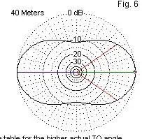
Here is what W4RNL predicted (same north-south antenna orientation): 


And here is the WSPR map that I got, again using about 250 milliwatts for about an hour): 


I think this pattern matches nicely with the prediction.  You don't see the nulls that you see in the 20 meter pattern.  You do see some stations directly north of me (as predicted).  There does not seem to be a big disparity in the geographic distribution of WSPR stations.

One note on the use of WSPR:  I started out using WSPR in receive mode, thinking that the pattern I'd see would be similar on receive or transmit  due to the antenna reciprocity principle.  But I worried that the results could be easily skewed by higher power WSPR stations.  So I shifted to the transmit mode and limited my output to 250 milliwatts. 


Here is the W4RNL chart showing the patterns for all the bands: 


Here is the azimuth chart for my location: 


Sunday, June 14, 2020

Dilbert, Shep, Dex, Pete, Farhan, and Wes! N2CQR Presentation on Homebrewing to Local Radio Club


Dean KK4DAS asked me to speak to our local radio club, the Vienna Wireless Society.   It was a lot of fun.  I talked about my evolution as a homebrewer, some of the rigs I made, the moments of joy, and the tales of woe.   You can watch the presentation in the video above. 

I was really glad to be able to explain in the presentation the importance of people like Pete, Dex, Farhan, Wes, Shep and even Dilbert. 

I was also pleased to get into the presentation the N2CQR sign that Peter VK2EMU made for me.  Thanks Peter! 

Here is the URL to the YouTube video (also above): 
https://www.youtube.com/watch?time_continue=3414&v=VHSr-v4QO7Q&feature=emb_logo

And here are the PowerPoint slides I used: 
https://viennawireless.net/wp/wp-content/uploads/2020/06/VWS-presentation-Rig-here-is-homebrew.pdf

Saturday, June 13, 2020

Jerry's Sproutie: A Short Wave Receiver (and a Limerick) by Jerry KI4IO


Jerry KI4IO is a really talented homebrewer;  I've called him the Wizard of Warrenton:  
and 

Warrenton Va. is not far from me (and is the birthplace of Cappucio the Wonder Dog).  Once we are done with the pandemic I hope that Jerry and I can get together to talk about homebrew radio.  

Like me, Jerry recently turned his attention to the shortwave broadcast bands. He too went the homebrew route, but his receiver is a regen.  It is based on the Sproutie by Dave AA7EE. 

Here is Jerry's article detailing the project and the results: 


Jerry had been scheduled to talk about antenna tuners at FDIM this year, but the pandemic caused the event to be canceled.  He shared with me a Limerick that he was going to include in the presentation.  Obviously we have similar feelings about automatic antenna tuners. 


In days of old
when hams we bold
and BALUNs weren't invented
We adjusted our C
and fiddled with L
and reflected power was prevented


KI4IO in his shack Feb 2020

Friday, June 12, 2020

Software for Computer Interface with NanoVNA: NanoVNASaver


In the UK, "brilliant" is high praise indeed.  So when Tony G4WIF told me that the NanoVNASaver software was brilliant, I took heed. 

Being able to use the tiny (nano!) device with your computer makes it a much more accessible and useful tool, especially for those of us with fat-finger syndrome. 

The photo above shows the NanoVNA measuring Return Loss and SWR  on my 40 meter dipole. You can see the identical Smith Chart traces on the two screens. 

Download and installation was very easy. I got my Windows PC version from here: 

Other versions available from here: 

Coincidently, a fellow just today put out a video on how to use this software with the NanoVNA. 

Thanks Tony! 

Wednesday, June 10, 2020

Alan Wolke W2AEW Explains the Vector Network Analyzer (VNA) (Video)


I told Alan that his video on VNAs was -- for me -- very timely.  The video popped up on YouTube on the day than my NanoVNA was being delivered.  TRGHS. 

Alan does a great job in explaining what the VNA does.  Particularly useful for me was his explanation of the VNA's ability to measure phase differences (through the use of directional couplers).  

I am having fun with my NanoVNA, happily measuring SWR and the bandpass characteristics of various filters.  Mine came with what looks like a guitar pick -- this is used as a stylus to hit the small boxes on the touch-screen.  A nice touch...   

I wish there was some good software for use with this VNA.  Apparently the nice software described by Joe Smith (yesterday's blog post) is quite expensive.  Is there a free alternative out there? 

Tuesday, June 9, 2020

NanoVNA, Millen Dip Meter, Kilo-Megacycles, and Measuring the Speed of Light (Video)


Yesterday my NanoVNA arrived.  This morning I was looking for info on how to use it and I found this really wonderful video from Joe Smith.  

Wow.  Joe gives a really useful intro to the capabilities of this amazing little device. He even reaches back in time and compares NanoVNA results with those obtained by a Millen Grid Dip Meter.  He pulls out of his junk box an attenuator that is so old that it is marked in "Kilo-Megacycles."  (Shouldn't we revive terms like that?)

Joe also gives us a taste of what it is like to live and work in the GHz range.  He warns us never to touch the SMA connectors on our NanoVNAs (too late Joe).  And -- get this -- he uses a torque wrench to connect the little SMA coax connectors to the NanoVNA.  I'm not kidding.  A torque wrench.   Joe connects surface mount capacitors and inductors that have their values specified not only in picofarads and microhenries, but also at the specific frequency at which they were measured.  

My understanding of the Smith Chart was greatly improved by watching Joe's video. 

Icing on the cake:  Joe wraps up the video by using the NanoVNA to MEASURE THE SPEED OF LIGHT.  Great stuff.  Thanks Joe.  

Here is Joe Smith's YouTube channel:  
https://www.youtube.com/channel/UCsK99WXk9VhcghnAauTBsbg

Now I have to get the software to use the NanoVNA with my computer. 
Designer: Douglas Bowman | Dimodifikasi oleh Abdul Munir Original Posting Rounders 3 Column