Podcasting since 2005! Listen to Latest SolderSmoke

Tuesday, December 7, 2021

Junk Box Sideband from the Azores (2004 QST Article)


About 20 years after I first built it, I find myself working on and using this SSB transmitter.    I recently added some impedance matching to the Swan 240 crystal filter;  several years ago I replaced the PA with a "JBOT" amplifier designed by Farhan VU2ESE.  I now have it on the air, using it with a highly modified Doug DeMaw, Barebones "Barbados" superhet  receiver. I had my first (recent!) QSO with this station yesterday, with Les 6Y6Y on the beach in Negril, Jamaica. 

More on this project in due course. Lots of soul in this machine. 

I'd forgotten about this article -- thanks to Pete Eaton for reminding me. Click on the images for a better look at the article. For an even clearer view, download the images and then open them on your computer. 


Monday, December 6, 2021

Early Radio in New Zealand, and "The Knack"


Thanks to Thomas K4SWL of the SWLing Post for alerting us to this gem.  Listen to Sarah Johnston's program describing the origins and early years of broadcast radio in New Zealand. 


This wonderful recording and article reminded me of a bit of ham radio history involving New Zealand,  and someone who was involved who had a surname similar to mine.  The ARRL book "200 Meters and Down" by Clinton DeSoto reports on page 91 that on May 22, 1924, radio amateurs for the first time made a contact between New Zealand and South America.  Carlos Braggio operated rCB8 in Buenos Aires.  In New Zealand, J.H. O'Meara was at the key in Gisborne. 

Writing of the early amateurs,  DeSoto wrote (on page 92): 

 "Why did they do it?  None but one of them can know, and only he would know the feeling of driving ambition, the relentless call of work to be done, the gnawing discontent that hungers for accomplishment; it would be hard to put into words. The strange thing is that there were folk, everywhere on earth it seemed, who had that urge." 

"The gnawing discontent..."  That is what Jean Shepherd had when he couldn't get his Heising Modulator to work properly.  We've all been there. 

The last line in the quote from DeSoto's book speaks to one of the major themes of this blog and of the SolderSmoke podcast:  the way in which people all around the world got interested in radio in much the same way.  So many of us, all around the world,  often at age 13 or 14, suddenly got interested in radio.  We all had (and have!) "The Knack."  This is really very nice -- it is something that we have in common, something that pulls us together. 

Sunday, December 5, 2021

Jack NG2E's Winter SOTA Marathon in the Shenandoah


Our friend Jack NG2E is a homebrewer.  He is also a Summits-On-The-Air guy. He does much of his SOTA operations along Skyline Drive in the Shenandoah National Park. Jack's Story Map method of documenting this SOTA trip is very cool. 

Elisa and I are frequent visitors to this amazing park.   Both my kids went to college in the Shenandoah valley, and the park starts just one hour by car west of us.  It is a beautiful place. The Appalachian Trail runs through the park;  we have crossed paths with "through hikers" who are walking from Maine to Georgia. We have also met up with more than one Black Bear in the park (see below).  My son Billy and I launched our Green Hornet rocket from a farm in the Shenandoah valley: https://soldersmoke.blogspot.com/2017/05/still-photos-and-slow-motion-video-from.html

I really like Jack's use of both HF and 2 meter FM.  This makes me think that I should blow the dust off my Baofeng HT and bring it out to the Shenandoah next time we visit.  Jack's 20 meter CW contact with Christian F4WBN in the Pyrenees added a nice element of transatlantic mountain symmetry.  

Check out Jack's Shenandoah Story Map: 

https://storymaps.arcgis.com/stories/c9ff4a13eca24b37bc9dcda0d2dce989

Here's another story map from a SOTA trip into the Adirondacks with info on his gear: 

https://storymaps.arcgis.com/stories/594ca069a27147c1a8d8b79dc1513a72

I know that Jack wants to include a homebrew rig in his SOTA operations.  That would significantly add to the already very high level of operational coolness.  Perhaps Colin M1BUU or Paul VK3HN could provide some suggestions or encouragement in this area. 

Thanks Jack.  Happy trails. Regards to the bears!  

Saturday, December 4, 2021

Dean's Supercharged, 16-Watt, Furlough 2040, Simple SSB Rig


'Tis a thing of beauty. 

It is especially appropriate for us to use that Irish phrase because the design of the rig's new final amplifier is out of  Ireland. Our friend Dean KK4DAS added a 16 watt RF amplifier based on a design by EI9GQ to his homebrew N6QW Simple SSB rig.  Note the IBEW label on the top. 

Here is Dean's blog post on this wonderful project (with video and more pictures). 

Dean has it on the air and is getting good reports.  He has clearly come a LONG way from his Michigan Mighty Mite build of just two years ago.  FB OM. 

Here is Dean's build of the EI9GQ 16 Watt Final

Final final assembly! 


A Great Morning on the Old Military Radio Net: AB9MQ's Central Electronics 20A, W3EMD's Dynamotor, WU2D

Just a portion of Masa's shack

I usually try to listen in on the Old Military Radio Net on Saturday mornings (3885 kc).  Lately I listen with my Mate for the Mighty Midget receiver.  

This morning's session was especially good.  For me the highlight was when Masa AB9MQ called in from Normal, Illinois using his Central Electronics 20A (see below).   That was one of the earliest SSB rigs.  A phasing rig, it also ran AM (which was what Masa was using this morning).  He had it paired up with a Central Electronics 458 VFO.  You folks really need to check out Masa's QRZ.com page: 

https://www.qrz.com/db/AB9MQ

Buzz W3EMD called in from Rhinebeck, NY.  I could hear his dynamotor in the background.  Buzz said hello to Masa in Japanese.   FB.

Always great to hear Mike WU2D


Friday, December 3, 2021

Alan Wolke W2AEW: YouTube Silver Play Button Award, and ARRL Hudson Division 2020 Technical Achievement Award

Three cheers for Alan Wolke W2AEW, truly one of the great guys of homebrew ham radio.  Alan's wonderful YouTube videos have enlightened hams all around the world.  He is always there to answer questions and help hams (like me) who are at times struggling to understand technical concepts. 

Photo from the November 13, 2021 ARRL Hudson Division Awards Luncheon. That’s Alan with the ARRL CEO David Minster NA2AA, the Nobel Prize winning Dr. Joe Taylor K1JT, and 2021 Technical Achievement winner David DeCoons WO2X. Alan was presented with the division’s 2020 Technical Achievement award. 

Thursday, December 2, 2021

Peter Parker VK3YE Inducted Into QRP Hall of Fame


Wow, I was really pleased to learn that Peter Parker VK3YE was a 2021 inductee into the QRP Hall of Fame.  

This is a richly deserved honor.   Peter Parker  has been making extraordinary contributions to QRP and homebrewing for many years.  I remember reaching out to him when I was just getting started with homebrew phone gear.  I considered him a guru of DSB.  He helped me a lot.  Peter Parker was interviewed on the SolderSmoke podcast in 2013: 

Peter has published many books and has produced many YouTube videos.  He hosts an annual QRP gathering in his beloved home-town of Melbourne Australia that gets attention from solder-melters around the world.  

Three cheers for Peter Parker!  

Congratulations Peter! 

VK3YE's Web Site: https://vk3ye.com/

VK3YE's QRZ.com page:   https://www.qrz.com/db/VK3YE 

Thanks to VK3HN for alerting me to this. 

Wednesday, December 1, 2021

KI4IO in India and Nepal, and Discrete Homebrew Gilbert Cells


Jerry KI4IO is such an amazing homebrewer that he has been dubbed "The Wizard of Warrenton." The picture above shows Jerry during the early 1980s in the shack of Father Moran 9N1MM in Nepal. Jerry was also in India.  (I previously posted the info on Jerry's time in India and Nepal, but I didn't have this picture.  The picture makes it worthwhile to post the story again.)  From Jerry's QRZ.com page: 
-------------------------------

While in India I was licensed at VU2LHO and worked a lot of US hams with a 135' flat-top and open-wire feed. I had the antenna strung between two bamboo towers atop the embassy housing 2nd-story roof-top. I also put up a 3/8 wave vertical on the roof for 10 meters. That little antenna had 110 radials stapled into the roof screen and worked very well! The rig was a HW-101. I was in Kathmandu, Nepal from early 1980 to late 1982. I could not obtain a license there, but became good friends with Father Moran, 9N1MM, and would often spend time up at his place putting his Drake station on CW. Pretty cool being real DX! Back in the states in late 1982.

Here I am at one of my many visits to Father Moran's shack. 
---------------------------------
Check out Jerry's QRZ.com page: https://www.qrz.com/db/KI4IO

I got in touch with Jerry because Pete Eaton reminded me that Jerry had homebrewed a discrete transistor version of the NE602 Gilbert Cell Mixer, a device that I am very interested in. Nick G8INE also built one. 

Tuesday, November 30, 2021

Putting a Barebones Superhet on 17 Meters with an NE602 Converter (Video)


Armed now with a NanoVNA, I took a look at the passband of the 5 MHz filter in my Barebones Superhet (BBRX)  W4OP built it on a Circuit Board Specialist Board.  He put a 5 MHz CW filter in there;  I broadened the passband for phone by changing the values of the capacitors. Here is what the passband now looks like in the NanoVNA: 


This is what DeMaw would call an "LSB filter."  You would get much better opposite sideband rejection by using it with an LSB signal, placing the BFO/Carrier Oscillator slightly above the passband, in this case near 5.002 MHz. 

When I first built the down converter to get the 18.150 MHz signal down to the 7 MHz range (where I had the receiver running) I used an 11 MHz crystal for the NE602's local oscillator.  But this created a big problem:  18.150 - 11 =   7.150 MHz.  That is in the 40 meter band, but note:  NO SIDEBAND INVERSION.   Then in the BBRX  7.150 MHz - 2.150 MHz = 5 MHz  (the filter frequency) but again:  NO SIDEBAND INVERSION.   The signal started as a USB signal and remained a USB signal. 

I briefly tried shifting the BFO frequency to the other side of the filter passband.  If I could get it to around 4.985 MHz, it might work, but because the filter passband was so large, and because the crystal frequency was so low, I was unable to shift the crystal frequency that far.  In any case the results would have been less than ideal because of the "LSB" shape of the filter.  Back to the drawing board. 

I decided to cause one sideband inversion. 

At first I put a 25.175 MHz crystal module in my down converter.  This shifted the 17 meter phone band down to the 40 meter CW band.  It worked, but I cold hear strong 40 meter CW  signals being picked up by the wiring of the receiver (the box is plastic!).  I went back to the module jar in search of frequency that would move 17 meter phone to the 40 meter area (so I would not have to re-build the BBRX front end) but outside the actual 40 meter band.  

I ended up using a 25 MHz crystal in the down converter. 25 MHz - 18.150 MHz = 6.85 MHz WITH SIDEBAND INVERSION.  After checking on the NA5B Web SDR to see that there are no strong signals in the 6.835 to 6.89 MHz range, I retuned the output circuit on the converter and tweaked the input capacitor on the Barebones.  I shifted the VFO frequency down to 1.835 to 1.89 MHz and put the BFO at 5.002 MHz.   The receiver was inhaling on 17 meter SSB.  

One more change to the BBRX:  in his June 1982 QST article, DeMaw warned that trying to get speaker level audio out of the 741 op amp that he used would result in audio distortion.  And it did.  So I put one of those little LM386 boards I have been using into the BBRX box.  I just ran audio in from the wiper of the AF gain pot.  It sounds good.  

In effect this is my first double-conversion receiver.  I usually prefer single conversion, but this project has highlighted for me one of the advantages of double conversion for someone like me who eschews digital VFOs:   Starting with a crystal filter at 5 MHz,  with double conversion I could keep the frequency of the LC VFO low enough to ensure frequency stability.  That would have been impossible with a 5 MHz IF in a single conversion 17 meter rig.  But if I were starting from scratch for a 17 meter rig, I could stick with single conversion by building the filter at 20 MHz,  keeping the VFO in the manageable 2 MHz range. 

Now, on to the SSB transmitter.   The Swan 240 dual crystal lattice filter from the early 1960s needs some impedance matching. 

Sunday, November 28, 2021

How To Understand the NE-602 and the Gilbert Cell Mixer


I think the key to understanding the Gilbert Cell Double Balanced mixer is to separate out the three tasks that this device completes, and consider them one at a time, using different diagrams: 

1) It mixes two signals to produce sum and difference outputs. 
2) It balances out the RF input. 
3) It balances out the LO input. 

                                                                  Task 1 -- Mixing


The Gilbert cell is like the diode ring mixer in that it switches the polarity of the input signal at a rate set by the Local Oscillator. Another way of saying this is that the mixer multiplies the input signal by 1 and by -1. 

Steve Long of the University of California described the essence of this mixing this way (using the diagram above): 
 
An ideal double balanced mixer simply consists of a switch driven by the local oscillator that reverses the polarity of the RF input at the LO frequency.  http://literature.cdn.keysight.com/litweb/pdf/5989-9103EN.pdf

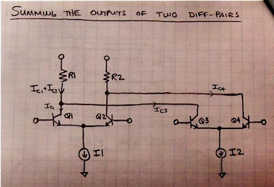
In an effort to see this for myself, I drew (noodled!) this diagram: 


There are four transistors -- two differential pairs with RF coming into the bases of the pairs. 
The LO is a square wave.  The LO alternately turns on transistors 1 and 4, then 2 and 3.  When 1 and 4 are on, we are in period 1 -- here there is no switching of polarity.  Portions of the RF waveform are passed to the outputs.  But when the LO turns on transistors 2 and 3, portions of the RF wave form are "crossed over" to the opposite output.  Polarity is reversed.  We see this in period number 2. 

Take a look at the resulting output waveforms.  This is the same waveform we see coming out of a diode ring mixer.  I really like this drawing because in that complex waveform you can actually see the sum and difference frequencies: 


I could see this diode ring waveform myself on my oscilloscope: 


TASK 2 -- Balancing Out the RF Input 

In a diode ring, and in other diode mixers, the balancing out of the input signals really takes place in the trifilar toroidal coils that are part of the circuit.  Barrie Gilbert needed an integrated circuit mixer that did not use coils.  


Again referring to the above diagram, Steve Long of the University of California put it this way: 

The ideal balanced structure above cancels any output at the RF input frequency since it will average to zero.

To fully understand this I find it helps to look at the Gilbert cell circuit drawn in a different way.  Here is a drawing from Alan Wolke W2AEW that I found very helpful. It comes from his excellent YouTube video: https://www.youtube.com/watch?v=7nmmb0pqTU0


Suppose the RF waveform at I1 is causing the current through R1 and R2 to increase.  At the same time, the opposite phase current through I2 will be causing the current through R1 and R2 to DECREASE.  So there is no net effect of the RF signal at the output.  The RF is balanced out. 

TASK 3 - Balancing Out the Local Oscillator Signal 


Here too I used my own drawing, and was guided by the words of Steve Long: 

It also cancels out any LO frequency component since we are taking the IF output as a differential signal and the LO shows up as common mode.  

The important thing to realize here is which transistors are being turned on and off by the local oscillator signal.  On one half cycle of the LO, transistors 1 and 4 are on.  So  the LO signal at the LO frequency are both pulling the same amount of LO frequency current through the resistors. So you have the same change in voltage at the output terminals.  And the output terminals are differential.  The LO signal results in no voltage difference between the terminals.  So the LO frequency is balanced out. 

The same thing happens on the following half of the LO cycle.  Here, transistors 2 and 3 are turned on. Again, both transistors pull the same amount of LO frequency current through the resistors. There is no differential voltage.  So no LO frequency energy passes to the output.  LO frequency is balanced out. 

--------------------------------

I am surrounded by Gilbert Cell Mixers and I have been using them in my homebrew rigs for many years. I use them in up-converters for my RTL-SDR receivers.  I have one in the downconverter for my 17 meter receiver and had one as the mixer in my first SSB transmitter. I built a 40 meter SSB transceiver with NE602s on either end of the crystal filter. Years ago, I built a DSB transceiver with several NE602s.  My SST QRP CW transceiver is made with NE602s. I have on my bookshelf Rutledge's book "The Electronics of Radio" that is all about the NORCAL 40 transceiver, built using NE602 chips.  But until now I really didn't know how these chips worked.  Truth be told, for me they were mysterious little black boxes, and that bothered me.  Now I feel a lot better about using these clever devices.  I plan on stocking up on the old style (non-SMD) NE602s.  

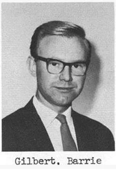
Apparently Barrie Gilbert rejected the idea that he invented the circuit that bears his name.  It seems that Howard Jones first used this circuit in 1963, with Gilbert developing it independently (in an improved form) in 1967. 

 Barrie Gilbert was quite a guy, with electronic roots in the world of tinkering: 


Saturday, November 27, 2021

The Galway Radio Experimenters Club


My old friend Mike EI0CL used to remind me that hams in Ireland are granted not just an amateur radio license, but an amateur radio experimenter's license, with an emphasis on experimentation. I think we can see that emphasis in the newsletter of the club.  It has a remarkably high level of technical content.  Check it out, and look at more information on the club: 


Here is their latest newsletter: 

Pete N6QW's PSST rig is mentioned on Page 4 of the Winter 2021 edition. TRGHS. 

Thanks to John EI7GL for alerting us to this gem via his FB blog

Wednesday, November 24, 2021

Gloria -- A Netflix Series about a Shortwave Broadcast Station in Portugal


Rarely if ever will we come across a high quality NETFLIX series built around a shortwave broadcast transmitter.  But that is what we have in Gloria.    It is really good.  We were especially interested in it because we lived in Portugal for three years. In addition to all the intrigue and drama you will catch glimpses of broadcast antennas, big transmitting tubes,  and one out-of-focus shot of what appears to be a Hallicrafters receiver (SX-42?)   

More info here: 

https://www.forbes.com/sites/sheenascott/2021/11/13/gloria-netflixs-first-original-series-from-portugal-is-a-great-spy-thriller/?sh=446cef9b30d7

Here's the NETFLIX link: 

https://www.netflix.com/title/81073977

Thanks to Thomas K4SWL of SWLing Post for the heads up


Designer: Douglas Bowman | Dimodifikasi oleh Abdul Munir Original Posting Rounders 3 Column